- Table of Contents
- Related Documents
-
| Title | Size | Download |
|---|---|---|
| 01-About the Router | 2.86 MB |
Contents
1 About the router
Unless otherwise stated, MPUs, interface modules, and fabric modules are collectively referred to as "modules" in this document.
Chassis views
Figure1-1 Front view
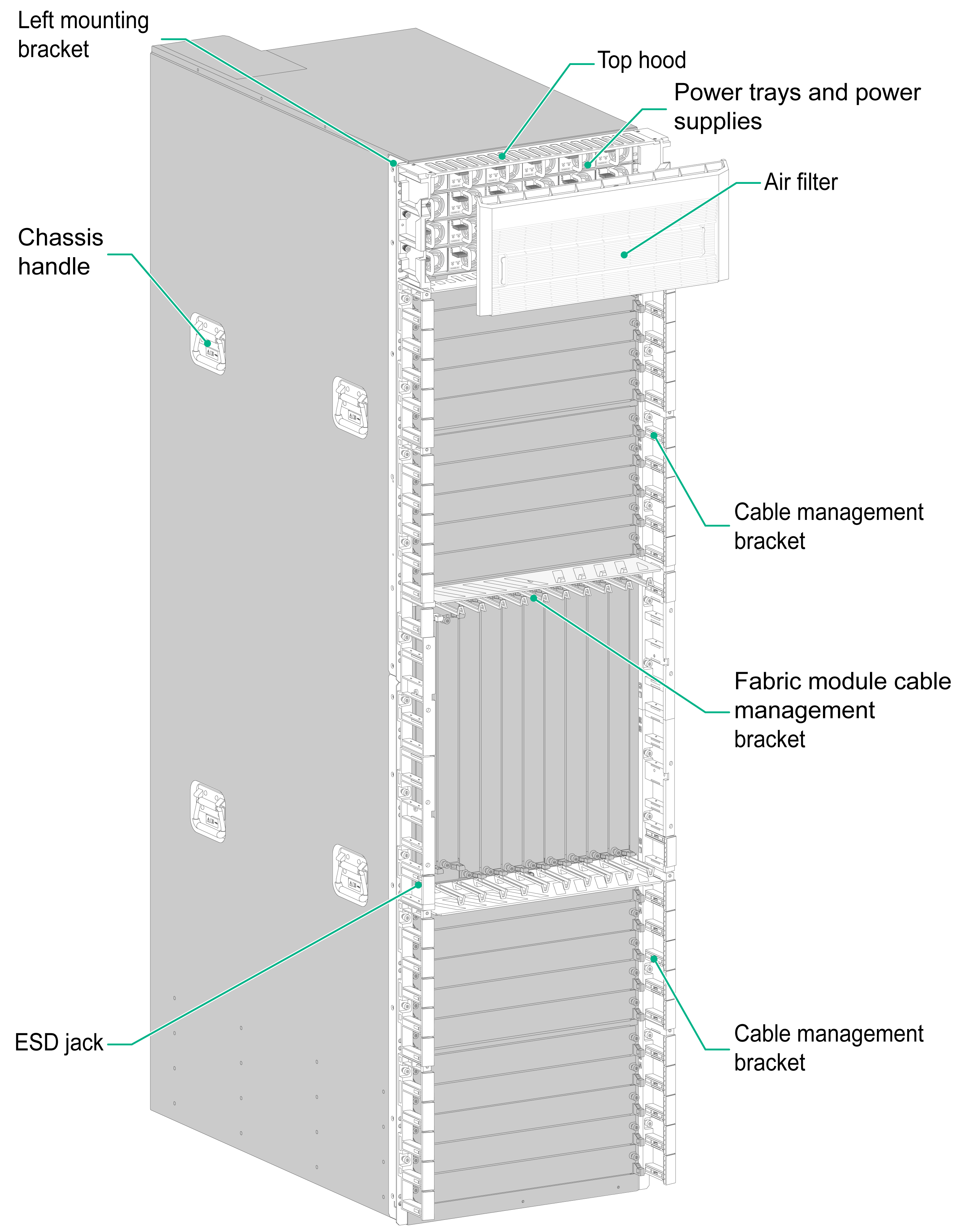
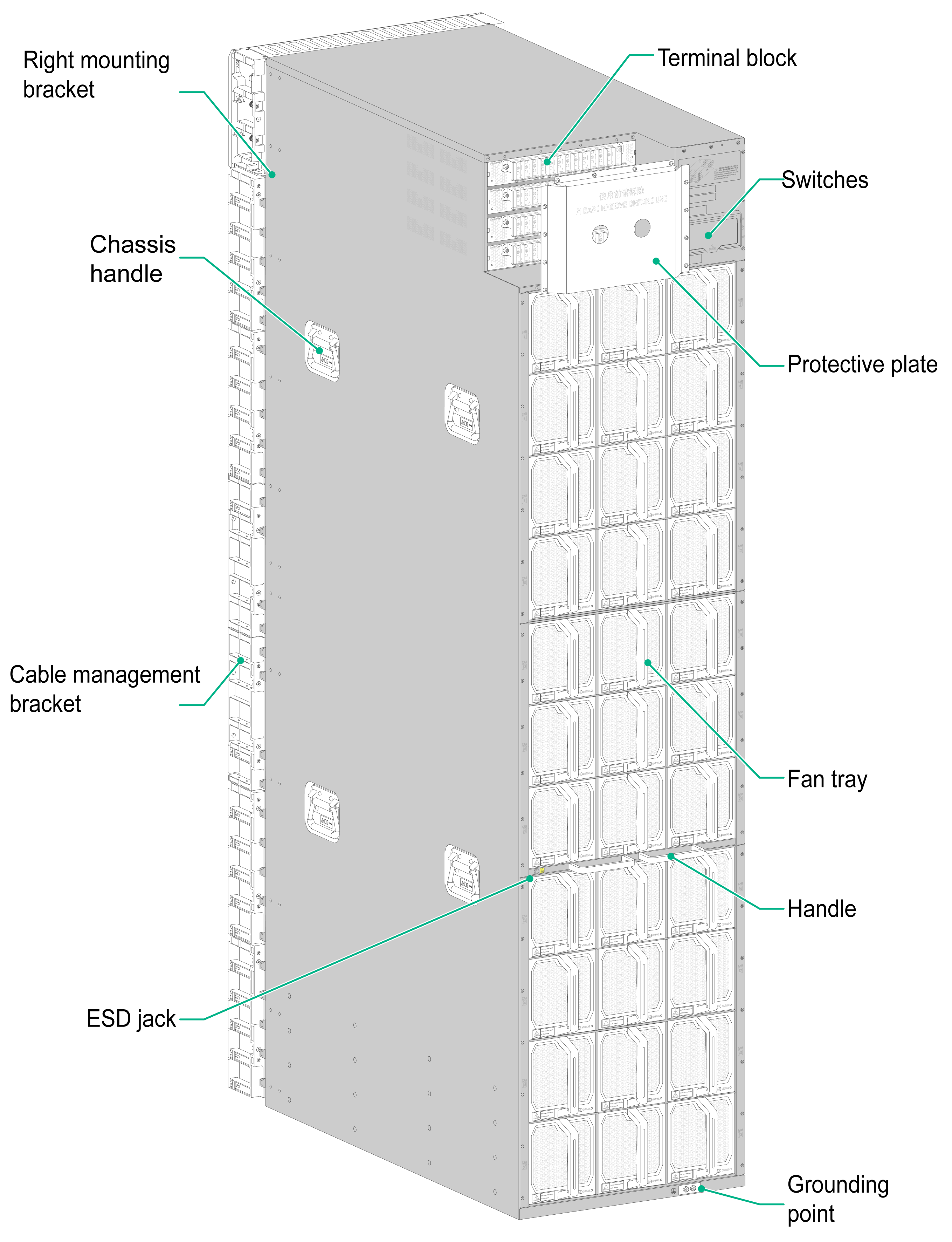
Figure1-2 Rear view
Slot arrangement
"LPU" in Figure1-3 refers to an interface module, "SFU" refers to a single-chassis fabric module, "MSFU" refers to a multi-chassis fabric module, and "PEM" refers to a power tray.
Figure1-3 Main sections of the router
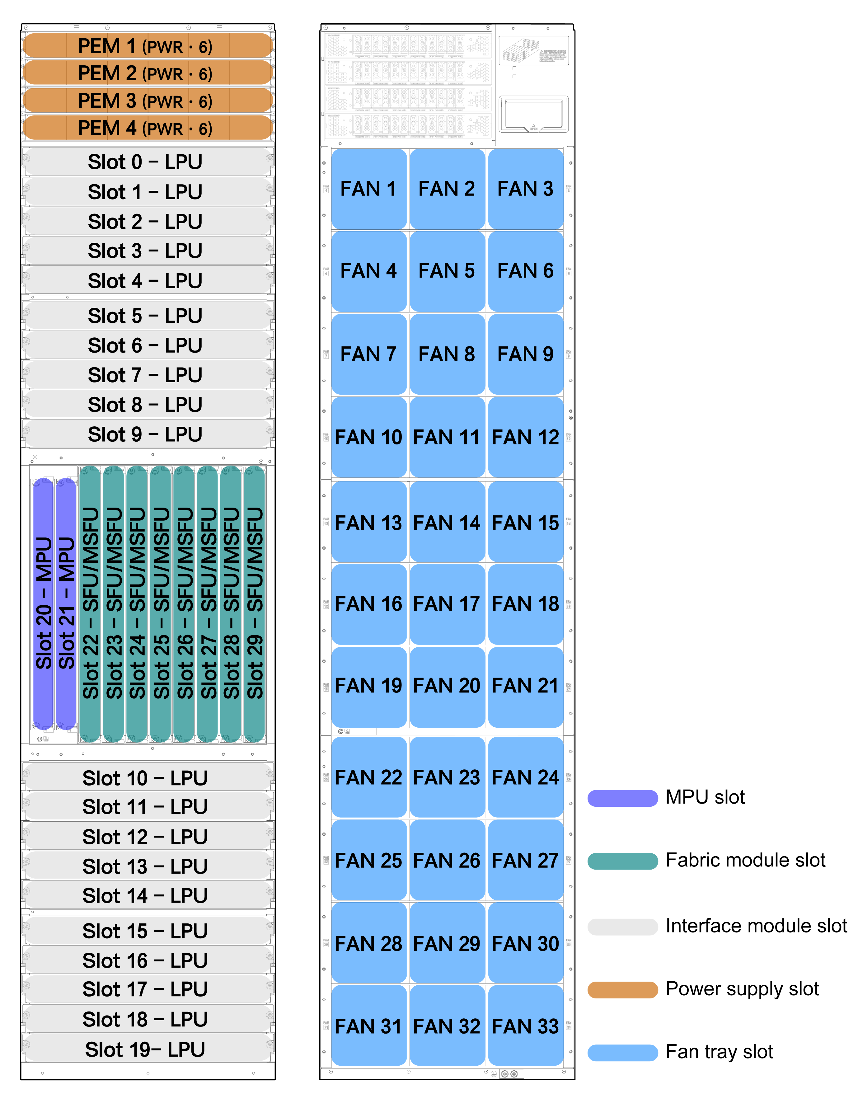
Table1-1 Descriptions for the router sections
|
Section |
Slots |
Description |
|
Interface module section |
20 interface module slots (slots 0 to 9 and slots 10 to 19) |
Determine the interface module models and quantities as required. The router allows mixture of different models of interface modules. |
|
MPU section |
2 MPU slots (slots 20 and 21) |
You can install one MPU, or two MPUs for redundancy for the router. To install one MPU for the router, you can install it in either of the MPU slots. The router does not allow mixture of different models of MPUs. |
|
Fabric module section |
8 fabric module slots (slots 22 to 29) |
The router supports a maximum of eight fabric modules. This software version supports only slots 22 to 27. Slots 28 and 29 are reserved for future use. The router does not allow mixture of different models of fabric modules. |
|
Power supply section |
4 power tray slots, each providing 6 power supply slots |
The router supports N+M (single DC power input source) or N+N (dual AC power input sources) power supply redundancy. Determine the number of power supplies based on the power input mode and system power consumption. |
|
Fan tray section |
33 fan tray slots at the rear of the chassis |
The 33 fan tray slots are arranged in 11 rows, with each row having 3 fan tray slots. Before starting the router, make sure each fan tray slot has a fan tray installed. You can operate the router only when it is fully configured with fan trays. |
Technical specifications
|
Item |
Description |
|
Dimensions (H × W × D) |
1820 × 440 × 850 mm (71.65 × 17.32 × 33.46 in) (41 RUs) |
|
Shipping weight |
416.0 kg (917.11 lb) |
|
Weight (chassis with mounting brackets and filler panels) |
198.0 kg (436.51 lb) |
|
Weight (fully configured) |
600.0 kg (1322.75 lb) |
|
Router weight |
Chassis weight (including mounting brackets and filler panels) plus removable component weight (including modules, power supplies, fan trays, and other removable components) |
|
System power consumption |
Sum of the power consumption of all modules and the power consumption of all configured fan trays |
|
Heat dissipation (per hour) |
0.9 × (power consumption of all modules plus power consumption of all configured fan trays)/0.9 × 3.4121 |
|
Sound pressure level (fully configured with 33 fan trays) in the acceptable temperature ranges |
≤ 78 dBA |
|
Rack |
2200 × 600 × 1200 mm (86.61 × 23.62 × 47.24 in) As a best practice, purchase the RACK-47U612-AX rack. |
|
Slide |
LSXM1BSR |
|
Temperature |
· Operating: 0°C to 45°C (32°F to 113°F) · Storage: –40°C to +70°C (–40°F to +158°F) |
|
Relative humidity |
· Operating: 5% RH to 95% RH (noncondensing) · Storage: 5% RH to 95% RH (noncondensing) |
|
|
NOTE: · Rack height is measured in RUs. One RU is 44.45 mm (1.75 in). · Dimensions in the table are for the chassis only, excluding the mounting brackets, cable management brackets, modules, and power supplies. · Heat dissipation is measured in BTU/h. 1 W equals 3.4121 BTU/h. · The sound pressure levels are measured based on the method specified in ISO 7779 at bystander positions. |
Interface numbering
Conventions
The interfaces on the router are numbered in the interface-type W/X/Y/Z format. The management port number on the MPU is 1/0/0/0.
Where,
· interface-type—Interface type, for example, Gigabit Ethernet.
· W—Chassis ID of the router in the cluster. In single-chassis mode, the number is 1. In back-to-back cluster mode, the numbers are 1 and 2.
· X—Number of the slot where the module resides, as shown by the number in Figure1-3.
· Y—The number depends on the interface module type.
¡ CR-19K-LPU-2002, CR-19K-LPU-2002B, CR-19K-LPU-4004, or CR-19K-LPU-8004 interface module—Number of the slot where the interface subcard resides on the interface module.
¡ Interface modules other than CR-19K-LPU-2002, CR-19K-LPU-2002B, CR-19K-LPU-4004, and CR-19K-LPU-8004—0.
· Z—Number of the interface on the interface subcard or interface module.
Examples
The router is in single-chassis mode. A CR-HIC-GP12 interface subcard is installed on a CR-19K-LPU-4004 interface module in slot 3 of the router.
· If the CR-HIC-GP12 subcard is installed in slot 1 of the CR-19K-LPU-4004 interface module, Gigabit Ethernet ports 1 to 12 on the CR-HIC-GP12 subcard are numbered GigabitEthernet 1/3/1/1 to GigabitEthernet 1/3/1/12, respectively.
· If the CR-HIC-GP12 subcard is installed in slot 2 of the CR-19K-LPU-4004 interface module, Gigabit Ethernet ports 1 to 12 on the CR-HIC-GP12 subcard are numbered GigabitEthernet 1/3/2/1 to GigabitEthernet 1/3/2/12, respectively.
