- Table of Contents
- Related Documents
-
| Title | Size | Download |
|---|---|---|
| 03-FRUs | 8.00 MB |
3 FRUs
For more information about modules and transceiver modules, see the card manuals or user guide for the router.
Weights, dimensions, and power consumptions
Modules
Table3-1 Module weights, dimensions, and power consumptions
|
Module model |
Net weight |
Dimensions (H × W × D) |
Power consumption |
|
CR-19K-MPU-08A |
4.1 kg (9.04 lb) |
45 × 284 × 512 mm (1.77 × 11.18 × 20.16 in) |
45 W |
|
CR-19K-MPU-08B |
4.6 kg (10.14 lb) |
45 × 284 × 512 mm (1.77 × 11.18 × 20.16 in) |
79 W |
|
CR-19K-SFU-08C |
4.0 kg (8.82 lb) |
40 × 284 × 521 mm (1.57 × 11.18 × 20.51 in) |
127 W |
|
CR-19K-MSFU-08A |
4.8 kg (10.58 lb) |
40 × 284 × 521 mm (1.57 × 11.18 × 20.51 in) |
135 W |
|
CR-19K-LPU-CQ18 |
11.8 kg (26.01 lb) |
50 × 433 × 520 mm (1.97 × 17.05 × 20.47 in) |
1390 W |
|
CR-19K-LPU-CQ12 |
11.5 kg (25.35 lb) |
50 × 433 × 520 mm (1.97 × 17.05 × 20.47 in) |
1130 W |
|
CR-19K-LPU-CQ12B |
11.6 kg (25.57 lb) |
50 × 433 × 520 mm (1.97 × 17.05 × 20.47 in) |
1224 W |
|
CR-19K-LPU-CQ06B |
11.4 kg (25.13 lb) |
50 × 433 × 520 mm (1.97 × 17.05 × 20.47 in) |
1115 W |
|
CR-19K-LPU-CC08 |
10.1 kg (22.27 lb) |
50 × 433 × 520 mm (1.97 × 17.05 × 20.47 in) |
835 W |
|
CR-19K-LPU-CC04 |
9.8 kg (21.60 lb) |
50 × 433 × 520 mm (1.97 × 17.05 × 20.47 in) |
480 W |
|
CR-19K-LPU-CC04B |
10.0 kg (22.05 lb) |
50 × 433 × 520 mm (1.97 × 17.05 × 20.47 in) |
827 W |
|
CR-19K-LPU-XP72 |
10.6 kg (23.37 lb) |
50 × 433 × 520 mm (1.97 × 17.05 × 20.47 in) |
830 W |
|
CR-19K-LPU-XP48 |
10.5 kg (23.15 lb) |
50 × 433 × 520 mm (1.97 × 17.05 × 20.47 in) |
750 W |
|
CR-19K-LPU-XP40 |
9.7 kg (21.38 lb) |
50 × 433 × 520 mm (1.97 × 17.05 × 20.47 in) |
595 W |
|
CR-19K-LPU-XP20CC02 |
9.7 kg (21.38 lb) |
50 × 433 × 520 mm (1.97 × 17.05 × 20.47 in) |
535 W |
|
CR-19K-LPU-8004 |
9.8 kg (21.60 lb) |
50 × 433 × 520 mm (1.97 × 17.05 × 20.47 in) |
880 W |
|
CR-19K-LPU-4004 |
7.4 kg (16.31 lb) |
50 × 433 × 520 mm (1.97 × 17.05 × 20.47 in) |
595 W |
|
CR-19K-LPU-2002 |
6.8 kg (14.99 lb) |
50 × 433 × 520 mm (1.97 × 17.05 × 20.47 in) |
350 W |
|
CR-19K-LPU-2002B |
7.4 kg (16.31 lb) |
50 × 433 × 520 mm (1.97 × 17.05 × 20.47 in) |
485 W |
|
CR-19K-LPU-SP |
6.3 kg (13.89 lb) |
50 × 433 × 520 mm (1.97 × 17.05 × 20.47 in) |
143 W |
|
CR-HIC-CLGQ04F |
0.8 kg (1.76 lb) |
21 × 195 × 162 mm (0.83 × 7.68 × 6.38 in) |
98 W |
|
CR-HIC-CQ02 |
0.6 kg (1.32 lb) |
21 × 195 × 162 mm (0.83 × 7.68 × 6.38 in) |
13 W |
|
CR-HIC-CQ01 |
0.5 kg (1.10 lb) |
21 × 195 × 162 mm (0.83 × 7.68 × 6.38 in) |
9 W |
|
CR-HIC-CC01 |
0.6 kg (1.32 lb) |
21 × 195 × 162 mm (0.83 × 7.68 × 6.38 in) |
25 W |
|
CR-HIC-QQ03 |
0.5 kg (1.10 lb) |
21 × 195 × 162 mm (0.83 × 7.68 × 6.38 in) |
10 W |
|
CR-HIC-XP12 |
0.6 kg (1.32 lb) |
21 × 195 × 162 mm (0.83 × 7.68 × 6.38 in) |
55 W |
|
CR-HIC-XP12B |
0.6 kg (1.32 lb) |
21 × 195 × 162 mm (0.83 × 7.68 × 6.38 in) |
34 W |
|
CR-HIC-XP10 |
0.6 kg (1.32 lb) |
21 × 195 × 162 mm (0.83 × 7.68 × 6.38 in) |
40 W |
|
CR-HIC-GP12 |
0.6 kg (1.32 lb) |
21 × 195 × 162 mm (0.83 × 7.68 × 6.38 in) |
55 W |
|
CR-HIC-PU02 |
0.5 kg (1.10 lb) |
21 × 195 × 162 mm (0.83 × 7.68 × 6.38 in) |
22 W |
|
CR-HIC-PS04 |
0.6 kg (1.32 lb) |
21 × 195 × 162 mm (0.83 × 7.68 × 6.38 in) |
19 W |
|
CR-HIC-PHP08 |
0.6 kg (1.32 lb) |
21 × 195 × 162 mm (0.83 × 7.68 × 6.38 in) |
20 W |
|
CR-HIC-CLP04 |
0.5 kg (1.10 lb) |
21 × 195 × 162 mm (0.83 × 7.68 × 6.38 in) |
17 W |
|
CR-HIC-ET16 |
0.5 kg (1.10 lb) |
21 × 195 × 162 mm (0.83 × 7.68 × 6.38 in) |
11 W |
|
|
NOTE: Module dimensions are expressed in the Height (H) × Width (W) × Depth (D) format: · H—Height of the front panel of the module. · W—Width of the front panel of the module. · D—Depth from the front panel of the module to the connector ends. (The depth includes the connectors and excludes the ejector levers and captive screws). |
Power supplies
Table3-2 Power supply weights and dimensions
|
Power supply model |
Net weight |
Dimensions (H × W × D) |
|
PSR2400-54A |
1.9 kg (4.19 lb) |
41 × 100 × 332 mm (1.61 × 3.94 × 13.07 in) |
|
PSR2400-54D |
1.9 kg (4.19 lb) |
41 × 100 × 332 mm (1.61 × 3.94 × 13.07 in) |
|
PSR3000-54A |
1.9 kg (4.19 lb) |
41 × 100 × 332 mm (1.61 × 3.94 × 13.07 in) |
Fan trays
The FAN-120B-2-A fan trays are available for the router.
Table3-3 Fan tray weights and dimensions
|
Fan tray model |
Net weight |
Dimensions (H × W × D) (Lying flat a workbench, including the handle) |
Power consumption |
|
FAN-120B-2-A |
2.1 kg (4.63 lb) |
144 × 927 × 183 mm (5.67 × 36.50 × 7.20 in) |
264 W |
LEDs
The major components of the router provide varieties of LEDs to indicate their operating status.
MPU LEDs
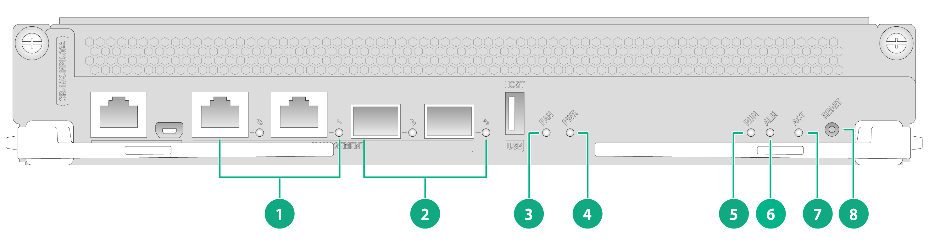
CR-19K-MPU-08A
Figure3-1 CR-19K-MPU-08A MPU LEDs
|
(1) Management port LEDs 0 and 1 |
(2) GE port LEDs 2 and 3 |
|
(3) Fan tray status LED (FAN) |
(4) Power supply status LED (PWR) |
|
(5) Module status LED (RUN) |
(6) System alarm LED (ALM) |
|
(7) MPU active/standby status LED (ACT) |
(8) Reset button |
Table3-4 CR-19K-MPU-8A MPU LED description
|
LED |
Status |
Description |
|
|
FAN |
Steady green |
All fan trays are operating correctly. |
|
|
Steady red |
· A minimum of one fan tray is faulty. · No fan tray is present in a minimum of one fan tray slot. |
||
|
PWR |
Steady green |
All present power supplies are operating correctly. |
|
|
Steady red |
A minimum of one power supply is faulty. |
||
|
RUN |
Slow flashing green (0.5 Hz) |
The modules are operating correctly. |
|
|
Fast flashing green (4 Hz) |
The modules are loading software.
To avoid module damage, do not power off the router or hot swap a module when the modules are loading software. |
||
|
Off |
A minimum of one module is faulty. |
||
|
ALM |
Off |
No alarm has occurred on the system. |
|
|
Steady red |
An alarm has occurred on the system. |
||
|
ACT |
Steady green |
The MPU is the active MPU of the chassis or the cluster. |
|
|
Flashing green (0.5 Hz) |
The router is in cluster mode, and the MPU is in standby mode. |
||
|
Off |
The router is in single chassis mode, and the MPU is in standby mode. |
||
|
MANAGEMENT 0 and 1 |
LINK/ACT |
Off |
No link is present on the port. |
|
Steady green |
A 1000 Mbps link is present on the port. |
||
|
Flashing green |
The port is sending or receiving data at 1000 Mbps. |
||
|
Steady yellow |
A 10/100 Mbps link is present. |
||
|
Flashing yellow |
The port is sending or receiving data at 10/100 Mbps. |
||
|
GE 2 and 3 |
LINK/ACT |
Off |
No link is present on the port. |
|
Steady green |
A link is present on the port. |
||
|
Flashing green |
The port is sending or receiving data. |
||
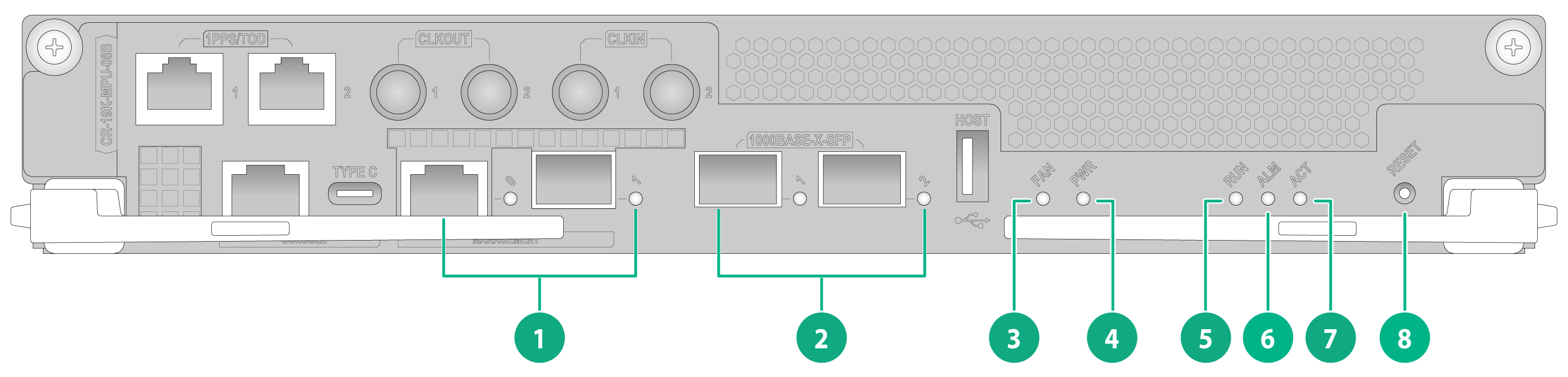
CR-19K-MPU-08B
Figure3-2 CR-19K-MPU-08B MPU LEDs
|
(1) Management port LEDs 0 and 1 |
(2) 1000BASE-X-SFP port LEDs 1 and 2 |
|
(3) Fan tray status LED (FAN) |
(4) Power supply status LED (PWR) |
|
(5) Module status LED (RUN) |
(6) System alarm LED (ALM) |
|
(7) MPU active/standby status LED (ACT) |
(8) Reset button |
Table3-5 CR-19K-MPU-8B MPU LED description
|
LED |
Status |
Description |
|
|
MANAGEMENT 0 and 1 |
LINK/ACT |
Off |
No link is present on the port. |
|
Steady green |
A 1000 Mbps link is present on the port. |
||
|
Flashing green |
The port is sending or receiving data at 1000 Mbps. |
||
|
Steady yellow |
A 10/100 Mbps link is present. |
||
|
Flashing yellow |
The port is sending or receiving data at 10/100 Mbps. |
||
|
1000BASE-X-SFP 1 and 2 |
LINK/ACT |
Off |
No link is present on the port. |
|
Steady green |
A link is present on the port. |
||
|
Flashing green |
The port is sending or receiving data. |
||
|
FAN |
Steady green |
All fan trays are operating correctly. |
|
|
Steady red |
· A minimum of one fan tray is faulty. · No fan tray is present in a minimum of one fan tray slot. |
||
|
PWR |
Steady green |
All present power supplies are operating correctly. |
|
|
Steady red |
A minimum of one power supply is faulty. |
||
|
RUN |
Slow flashing green (0.5 Hz) |
The modules are operating correctly. |
|
|
Fast flashing green (4 Hz) |
The modules are loading software.
To avoid module damage, do not power off the router or hot swap a module when the modules are loading software. |
||
|
Off |
A minimum of one module is faulty. |
||
|
ALM |
Off |
No alarm has occurred on the system. |
|
|
Steady red |
An alarm has occurred on the system. |
||
|
ACT |
Steady green |
The MPU is the active MPU of the chassis or the cluster. |
|
|
Flashing green (0.5 Hz) |
The router is in cluster mode, and the MPU is in standby mode. |
||
|
Off |
The router is in single chassis mode, and the MPU is in standby mode. |
||
Fabric module LEDs
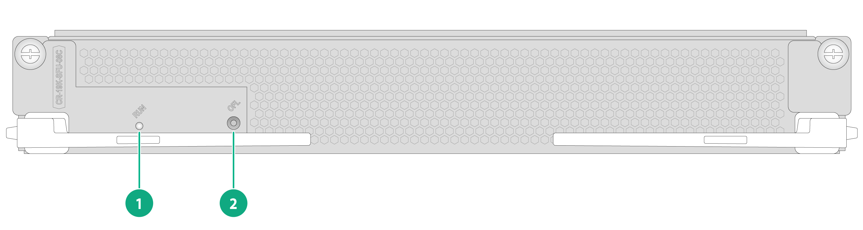
CR-19K-SFU-08C
Figure3-3 CR-19K-SFU-08C fabric module LEDs
|
(1) Running status LED (RUN) |
(2) OFL button |
Table3-6 CR-19K-SFU-08C fabric module LED description
|
LED |
Status |
Description |
|
RUN |
Flashing green (0.5 Hz) |
The fabric module is operating correctly. |
|
Flashing green (4 Hz) |
The fabric module is loading software.
To avoid damaging the fabric module, do not power off the router or hot swap the fabric module when the fabric module is loading software. |
|
|
Steady red |
An alarm has occurred on the fabric module. |
|
|
Flashing red (8 Hz) |
After you press the OFL button, the LED flashes red at 8 Hz for 3 seconds. You can remove the module after the LED is off. |
|
|
Off |
The fabric module is faulty. |
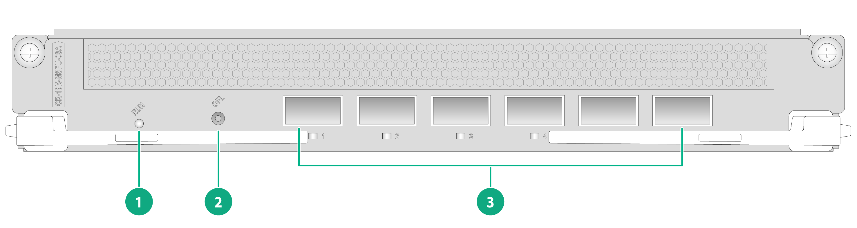
CR-19K-MSFU-08A
Figure3-4 CR-19K-MSFU-08A fabric module LEDs
|
(1) Running status LED (RUN) |
(2) OFL button |
|
(3) Cluster port LEDs 1 to 6 |
|
Table3-7 CR-19K-MSFU-08A fabric module LED description
|
LED |
Status |
Description |
|
RUN |
Flashing green (0.5 Hz) |
The fabric module is operating correctly. |
|
Flashing green (4 Hz) |
The fabric module is loading software.
To avoid damaging the fabric module, do not power off the router or hot swap the fabric module when the fabric module is loading software. |
|
|
Steady red |
An alarm has occurred on the fabric module. |
|
|
Flashing red (8 Hz) |
After you press the OFL button, the LED flashes red at 8 Hz for 3 seconds. You can remove the module after the LED is off. |
|
|
Off |
The fabric module is faulty. |
|
|
Cluster port LED 1 to 6 |
Off |
No link is present on the port. |
|
Steady green |
A link is present on the port. |
Interface module LEDs
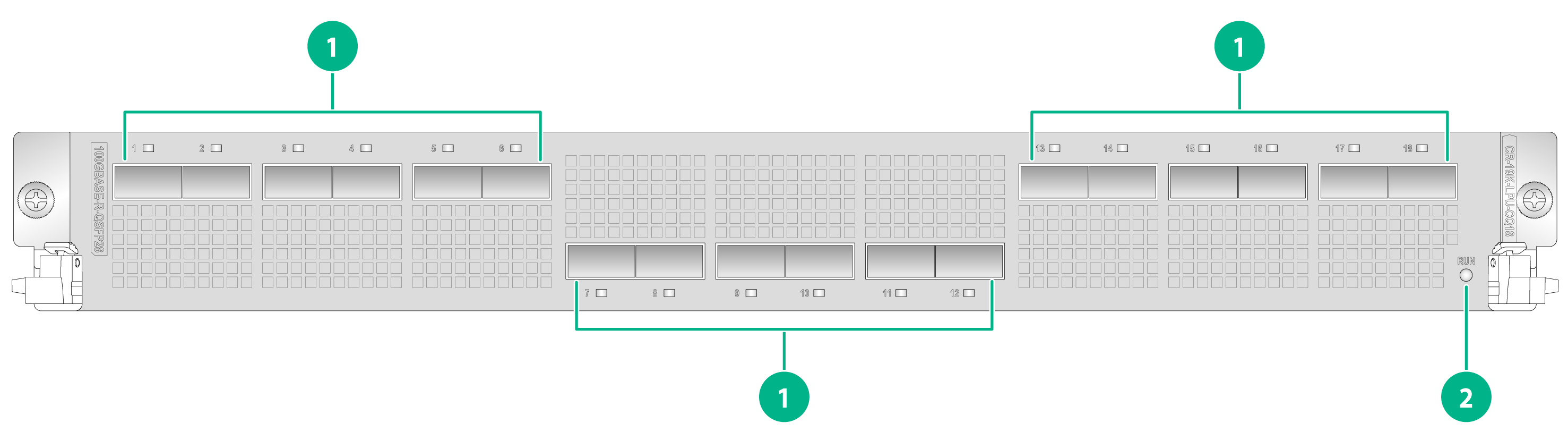
CR-19K-LPU-CQ18
Figure3-5 CR-19K-LPU-CQ18 interface module LEDs
|
(1) 100GBASE-R-QSFP28 Ethernet port LEDs 1 to 18 |
(2) Running status LED (RUN) |
Table3-8 CR-19K-LPU-CQ18 interface module LED descriptions
|
LED |
Status |
Description |
|
RUN |
Slow flashing green (0.5 Hz) |
The module is operating correctly. |
|
Fast flashing green (4 Hz) |
The module is loading software.
To avoid damaging the module, do not power off the router or hot swap the module when the module is loading software. |
|
|
Steady red |
An alarm has occurred on the module. |
|
|
Off |
The module is faulty. |
|
|
LINK/ACT (1 to 18) |
Off |
No link is present on the port. |
|
Steady green |
A link is present on the port. |
|
|
Flashing green |
The port is sending or receiving data. |
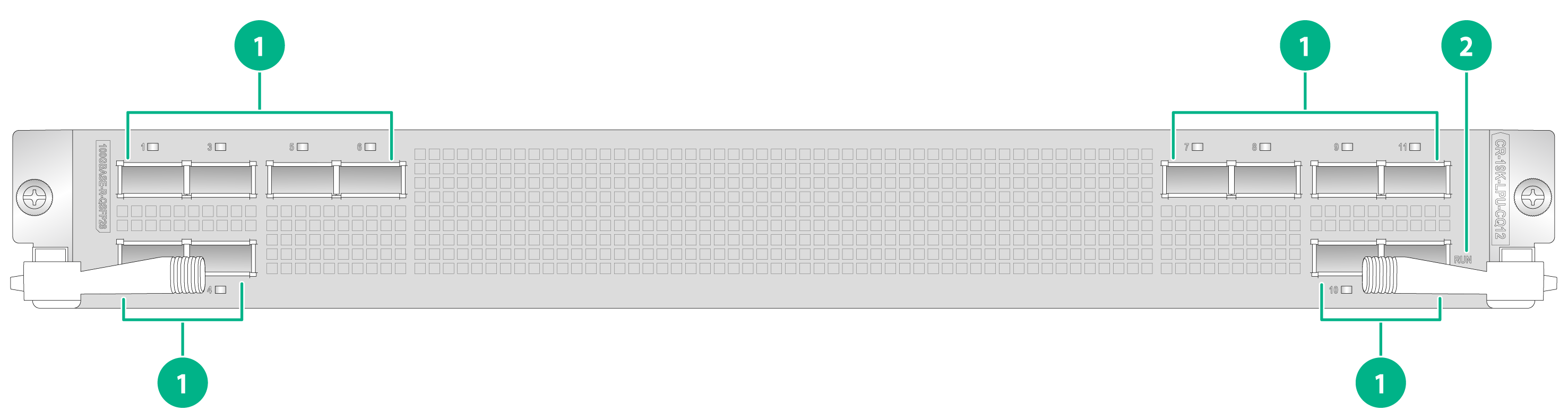
CR-19K-LPU-CQ12
Figure3-6 CR-19K-LPU-CQ12 interface module LEDs
|
(1) 100GBASE-R-QSFP28 Ethernet port LEDs 1 to 12 |
(2) Running status LED (RUN) |
Table3-9 CR-19K-LPU-CQ12 interface module LED description
|
LED |
Status |
Description |
|
RUN |
Slow flashing green (0.5 Hz) |
The module is operating correctly. |
|
Fast flashing green (4 Hz) |
The module is loading software.
To avoid damaging the module, do not power off the router or hot swap the module when the module is loading software. |
|
|
Steady red |
An alarm has occurred on the module. |
|
|
Off |
The module is faulty or not in place. |
|
|
LINK/ACT (1 to 12) |
Off |
No link is present on the port. |
|
Steady green |
A link is present on the port. |
|
|
Flashing green |
The port is sending or receiving data. |
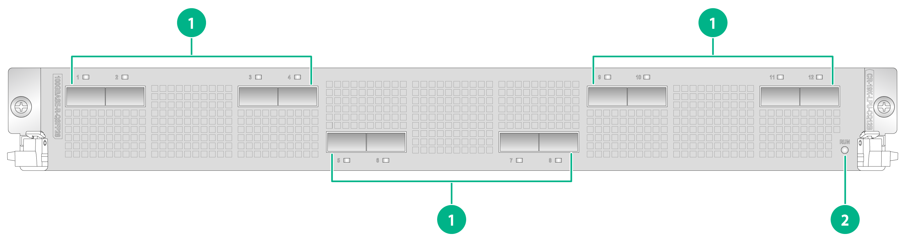
CR-19K-LPU-CQ12B
Figure3-7 CR-19K-LPU-CQ12B interface module LEDs
|
(1) 100GBASE-R-QSFP28 Ethernet port LEDs 1 to 12 |
(2) Running status LED (RUN) |
Table3-10 CR-19K-LPU-CQ12B interface module LED descriptions
|
LED |
Status |
Description |
|
RUN |
Slow flashing green (0.5 Hz) |
The module is operating correctly. |
|
Fast flashing green (4 Hz) |
The module is loading software.
To avoid damaging the module, do not power off the router or hot swap the module when the module is loading software. |
|
|
Steady red |
An alarm has occurred on the module. |
|
|
Off |
The module is faulty. |
|
|
LINK/ACT (1 to 12) |
Off |
No link is present on the port. |
|
Steady green |
A link is present on the port. |
|
|
Flashing green |
The port is sending or receiving data. |
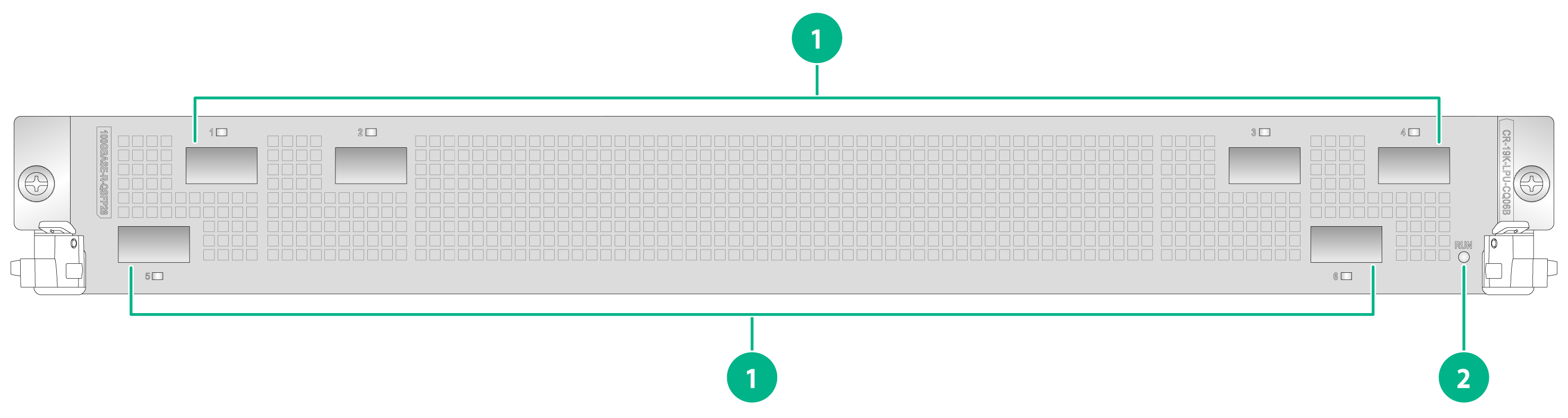
CR-19K-LPU-CQ06B
Figure3-8 CR-19K-LPU-CQ06B interface module LEDs
|
(1) 100GBASE-R-QSFP28 port LEDs 1 to 6 |
(2) Running status LED (RUN) |
Table3-11 CR-19K-LPU-CQ06B interface module LED description
|
LED |
Status |
Description |
|
RUN |
Slow flashing green (0.5 Hz) |
The module is operating correctly. |
|
Fast flashing green (4 Hz) |
The module is loading software.
To avoid damaging the module, do not power off the router or hot swap the module when the module is loading software. |
|
|
Steady red |
An alarm has occurred on the module. |
|
|
Off |
The module is faulty or not in place. |
|
|
LINK/ACT (1 to 6) |
Off |
No link is present on the port. |
|
Steady green |
A link is present on the port. |
|
|
Flashing green |
The port is sending or receiving data. |
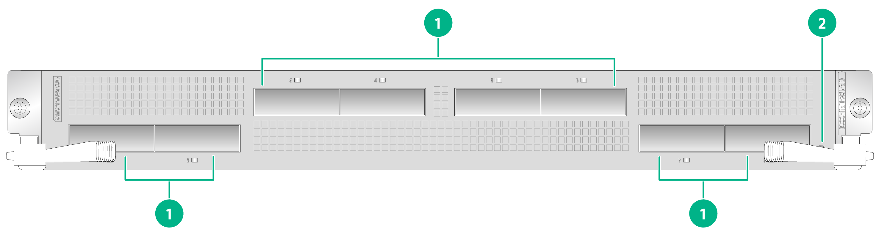
CR-19K-LPU-CC08
Figure3-9 CR-19K-LPU-CC08 interface module LEDs
|
(1) 100GBASE-R-CFP2 port LEDs 1 to 8 |
(2) Running status LED (RUN) |
Table3-12 CR-19K-LPU-CC08 interface module LED description
|
LED |
Status |
Description |
|
RUN |
Slow flashing green (0.5 Hz) |
The module is operating correctly. |
|
Fast flashing green (4 Hz) |
The module is loading software.
To avoid damaging the module, do not power off the router or hot swap the module when the module is loading software. |
|
|
Steady red |
An alarm has occurred on the module. |
|
|
Off |
The module is faulty or not in place. |
|
|
LINK/ACT (1 to 8) |
Off |
No link is present on the port. |
|
Steady green |
A link is present on the port. |
|
|
Flashing green |
The port is sending or receiving data. |
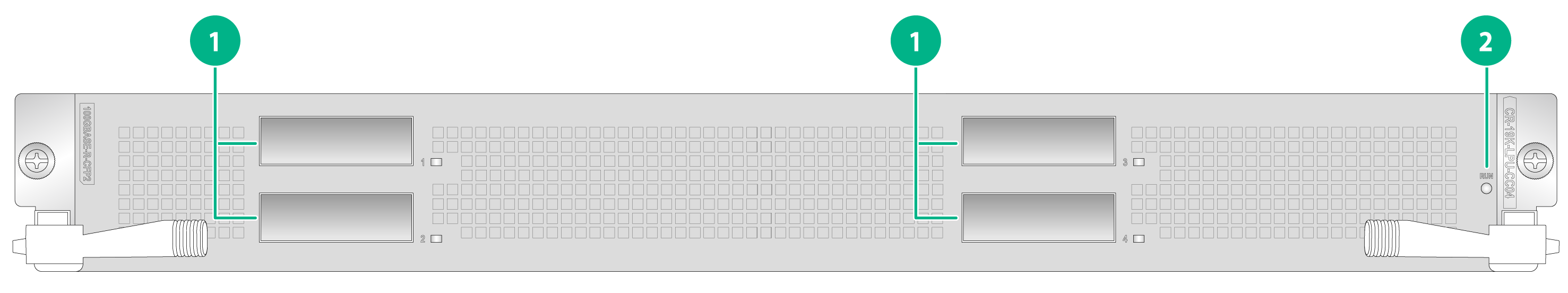
CR-19K-LPU-CC04
Figure3-10 CR-19K-LPU-CC04 interface module LEDs
|
(1) 100GBASE-R-CFP2 ports LEDs 1 to 4 |
(2) Running status LED (RUN) |
Table3-13 CR-19K-LPU-CC04 interface module LED description
|
LED |
Status |
Description |
|
RUN |
Slow flashing green (0.5 Hz) |
The module is operating correctly. |
|
Fast flashing green (4 Hz) |
The module is loading software.
To avoid damaging the module, do not power off the router or hot swap the module when the module is loading software. |
|
|
Steady red |
An alarm has occurred on the module. |
|
|
Off |
The module is faulty or not in place. |
|
|
LINK/ACT (1 to 4) |
Off |
No link is present on the port. |
|
Steady green |
A link is present on the port. |
|
|
Flashing green |
The port is sending or receiving data. |
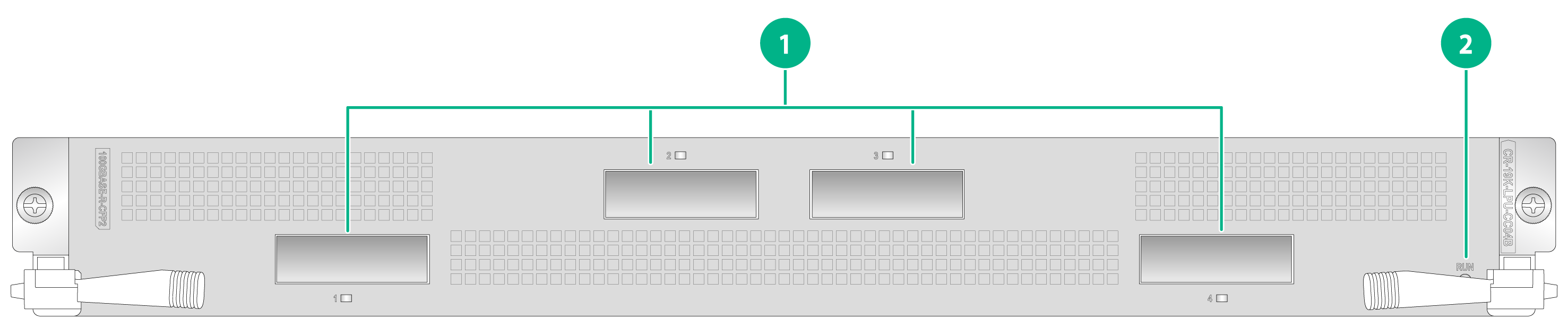
CR-19K-LPU-CC04B
Figure3-11 CR-19K-LPU-CC04B interface module LEDs
|
(1) 100GBASE-R-CFP2 port LEDs 1 to 4 |
(2) Running status LED (RUN) |
Table3-14 CR-19K-LPU-CC04B interface module LED description
|
LED |
Status |
Description |
|
RUN |
Slow flashing green (0.5 Hz) |
The module is operating correctly. |
|
Fast flashing green (4 Hz) |
The module is loading software.
To avoid damaging the module, do not power off the router or hot swap the module when the module is loading software. |
|
|
Steady red |
An alarm has occurred on the module. |
|
|
Off |
The module is faulty or not in place. |
|
|
LINK/ACT (1 to 4) |
Off |
No link is present on the port. |
|
Steady green |
A link is present on the port. |
|
|
Flashing green |
The port is sending or receiving data. |
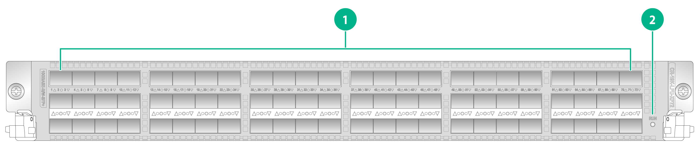
CR-19K-LPU-XP72
Figure3-12 CR-19K-LPU-XP72 interface module LEDs
|
(1) 10GBASE-R/W-SFP+ port LEDs 1 to 72 |
(2) Running status LED (RUN) |
Table3-15 CR-19K-LPU-XP72 interface module LED description
|
LED |
Status |
Description |
|
RUN |
Slow flashing green (0.5 Hz) |
The module is operating correctly. |
|
Fast flashing green (4 Hz) |
The module is loading software.
To avoid damaging the module, do not power off the router or hot swap the module when the module is loading software. |
|
|
Steady red |
An alarm has occurred on the module. |
|
|
Off |
The module is faulty or not in place. |
|
|
LINK/ACT (1 to 72) |
Off |
No link is present on the port. |
|
Steady green |
A link is present on the port. |
|
|
Flashing green |
The port is sending or receiving data. |
CR-19K-LPU-XP48
Figure3-13 CR-19K-LPU-XP48 interface module LEDs
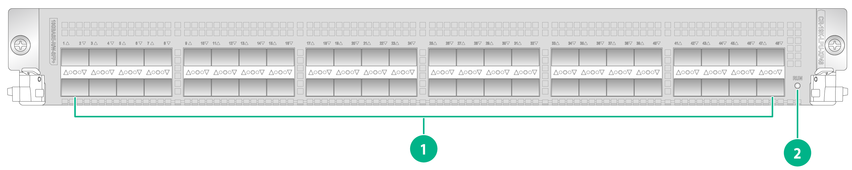
|
(1) 10GBASE-R/W-SFP+ port LEDs 1 to 48 |
(2) Running status LED (RUN) |
Table3-16 CR-19K-LPU-XP48 interface module LED description
|
LED |
Status |
Description |
|
RUN |
Slow flashing green (0.5 Hz) |
The module is operating correctly. |
|
Fast flashing green (4 Hz) |
The module is loading software.
To avoid damaging the module, do not power off the router or hot swap the module when the module is loading software. |
|
|
Steady red |
An alarm has occurred on the module. |
|
|
Off |
The module is faulty or not in place. |
|
|
LINK/ACT (1 to 48) |
Off |
No link is present on the port. |
|
Steady green |
A link is present on the port. |
|
|
Flashing green |
The port is sending or receiving data. |
CR-19K-LPU-XP40
Figure3-14 CR-19K-LPU-XP40 interface module LEDs
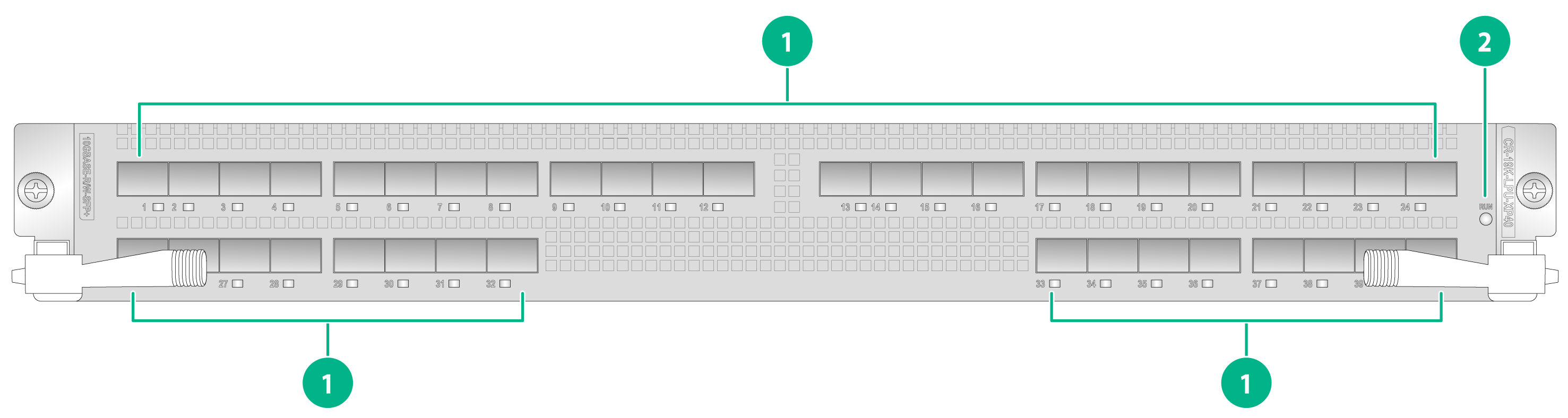
|
(1) 10GBASE-R/W-SFP+ port LEDs 1 to 40 |
(2) Running status LED (RUN) |
Table3-17 CR-19K-LPU-XP40 interface module LED description
|
LED |
Status |
Description |
|
RUN |
Slow flashing green (0.5 Hz) |
The module is operating correctly. |
|
Fast flashing green (4 Hz) |
The module is loading software.
To avoid damaging the module, do not power off the router or hot swap the module when the module is loading software. |
|
|
Steady red |
An alarm has occurred on the module. |
|
|
Off |
The module is faulty or not in place. |
|
|
LINK/ACT (1 to 40) |
Off |
No link is present on the port. |
|
Steady green |
A link is present on the port. |
|
|
Flashing green |
The port is sending or receiving data. |
CR-19K-LPU-XP20CC02
Figure3-15 CR-19K-LPU-XP20CC02 interface module LEDs
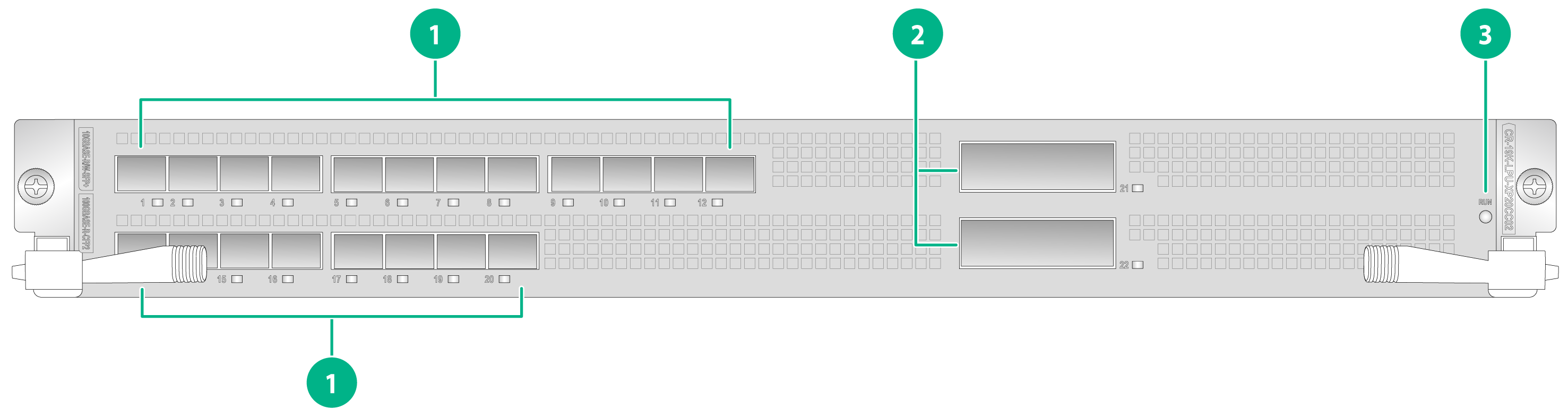
|
(1) 10GBASE-R/W-SFP+ port LEDs 1 to 20 |
(2) 100GBASE-R-CFP2 port LEDs 21 and 22 |
|
(3) Running status LED (RUN) |
|
Table3-18 CR-19K-LPU-XP20CC02 interface module LED description
|
LED |
Status |
Description |
|
RUN |
Slow flashing green (0.5 Hz) |
The module is operating correctly. |
|
Fast flashing green (4 Hz) |
The module is loading software.
To avoid damaging the module, do not power off the router or hot swap the module when the module is loading software. |
|
|
Steady red |
An alarm has occurred on the module. |
|
|
Off |
The module is faulty or not in place. |
|
|
LINK/ACT (1 to 22) |
Off |
No link is present on the port. |
|
Steady green |
A link is present on the port. |
|
|
Flashing green |
The port is sending or receiving data. |
CR-19K-LPU-8004
Figure3-16 CR-19K-LPU-8004 interface module LEDs
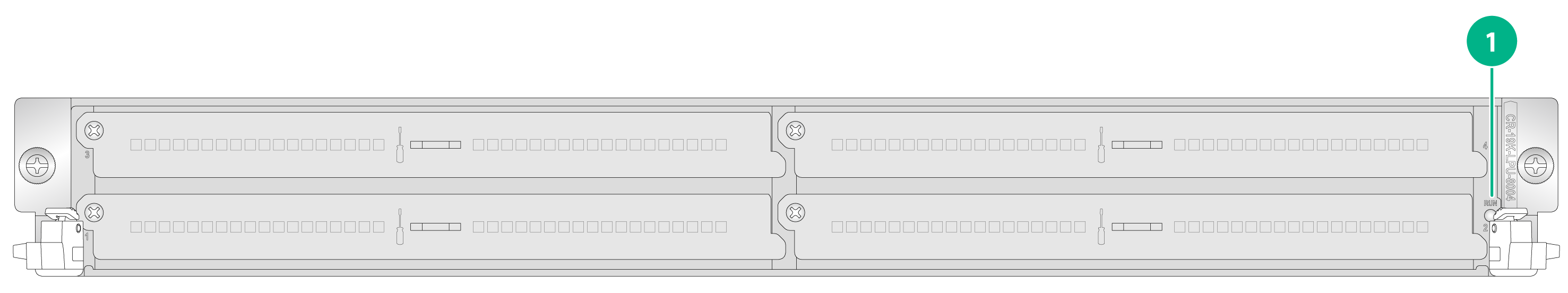
|
(1) Running status LED (RUN) |
Table3-19 CR-19K-LPU-8004 interface module LED descriptions
|
LED |
Status |
Description |
|
RUN |
Slow flashing green (0.5 Hz) |
The module is operating correctly. |
|
Fast flashing green (4 Hz) |
The module is loading software.
To avoid damaging the module, do not power off the router or hot swap the module when the module is loading software. |
|
|
Steady red |
An alarm has occurred on the module. |
|
|
Off |
The module is faulty. |
CR-19K-LPU-4004
Figure3-17 CR-19K-LPU-4004 interface module LEDs
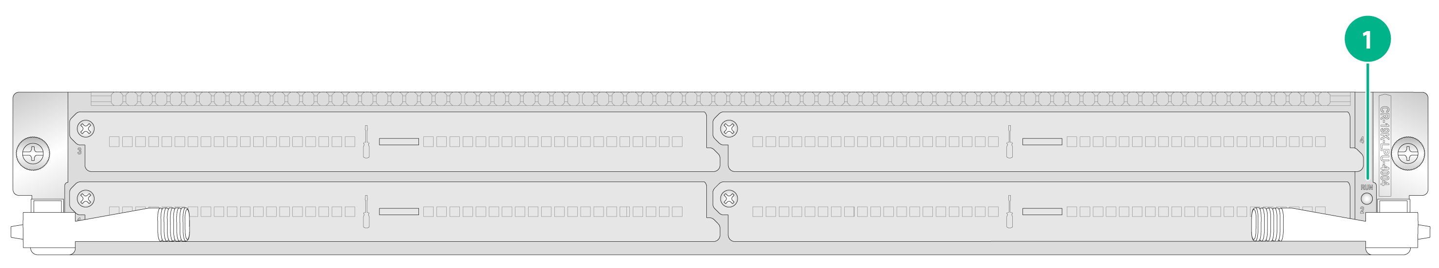
|
(1) Running status LED (RUN) |
Table3-20 CR-19K-LPU-4004 interface module LED description
|
LED |
Status |
Description |
|
RUN |
Slow flashing green (0.5 Hz) |
The module is operating correctly. |
|
Fast flashing green (4 Hz) |
The module is loading software.
To avoid damaging the module, do not power off the router or hot swap the module when the module is loading software. |
|
|
Steady red |
An alarm has occurred on the module. |
|
|
Off |
The module is faulty or not in place. |
CR-19K-LPU-2002
Figure3-18 CR-19K-LPU-2002 interface module LEDs
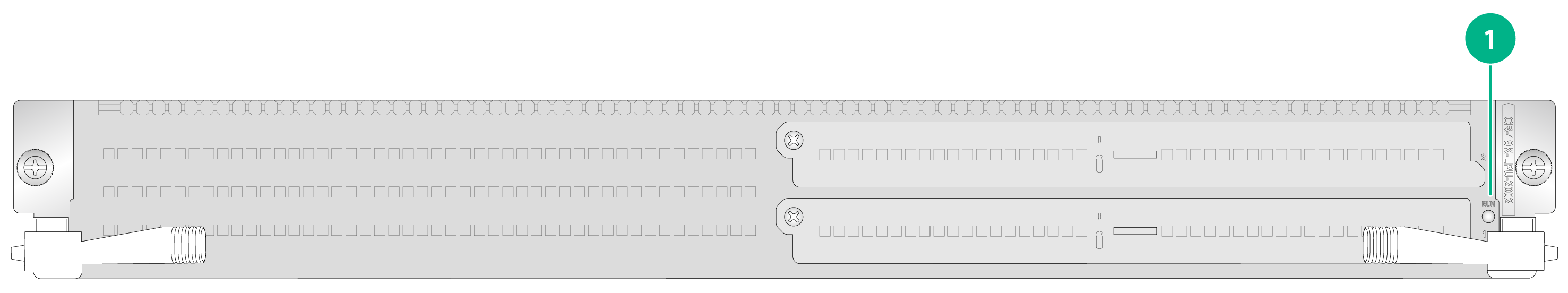
|
(1) Running status LED (RUN) |
Table3-21 CR-19K-LPU-2002 interface module LED description
|
LED |
Status |
Description |
|
RUN |
Slow flashing green (0.5 Hz) |
The module is operating correctly. |
|
Fast flashing green (4 Hz) |
The module is loading software.
To avoid damaging the module, do not power off the router or hot swap the module when the module is loading software. |
|
|
Steady red |
An alarm has occurred on the module. |
|
|
Off |
The module is faulty or not in place. |
CR-19K-LPU-2002B
Figure3-19 CR-19K-LPU-2002B interface module LEDs
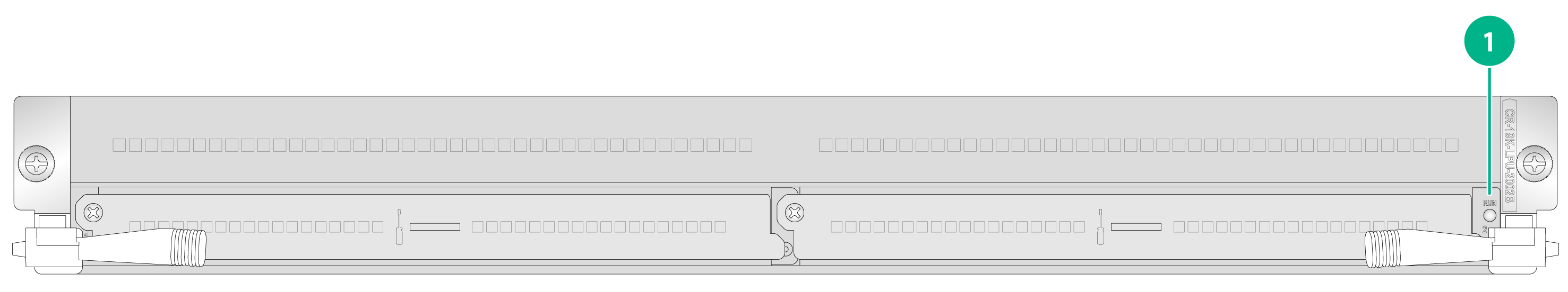
|
(1) Running status LED (RUN) |
Table3-22 CR-19K-LPU-2002B interface module LED description
|
LED |
Status |
Description |
|
RUN |
Slow flashing green (0.5 Hz) |
The module is operating correctly. |
|
Fast flashing green (4 Hz) |
The module is loading software.
To avoid damaging the module, do not power off the router or hot swap the module when the module is loading software. |
|
|
Steady red |
An alarm has occurred on the module. |
|
|
Off |
The module is faulty or not in place. |
CR-19K-LPU-SP
Figure3-20 CR-19K-LPU-SP interface module LEDs
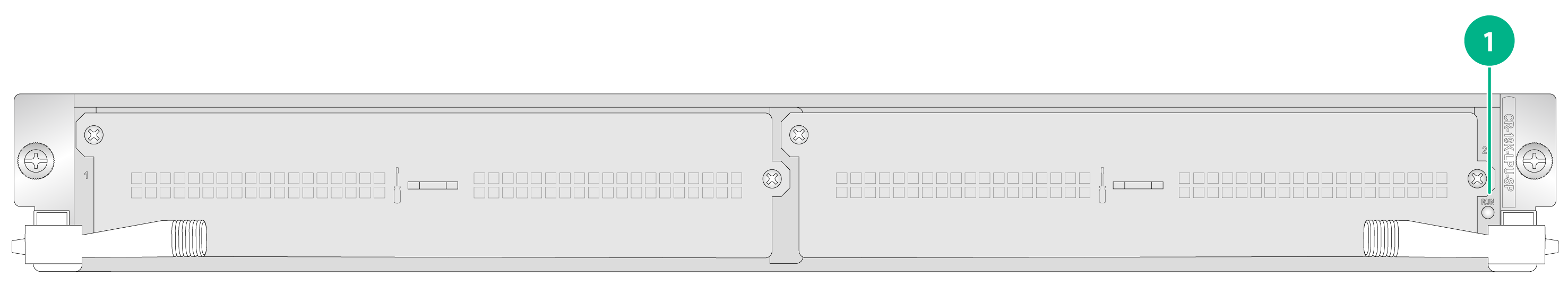
|
(1) Running status LED (RUN) |
Table3-23 CR-19K-LPU-SP interface module LED description
|
LED |
Status |
Description |
|
RUN |
Slow flashing green (0.5 Hz) |
The module is operating correctly. |
|
Fast flashing green (4 Hz) |
The module is loading software.
To avoid damaging the module, do not power off the router or hot swap the module when the module is loading software. |
|
|
Steady red |
An alarm has occurred on the module. |
|
|
Off |
The module is faulty or not in place. |
Interface subcard LEDs
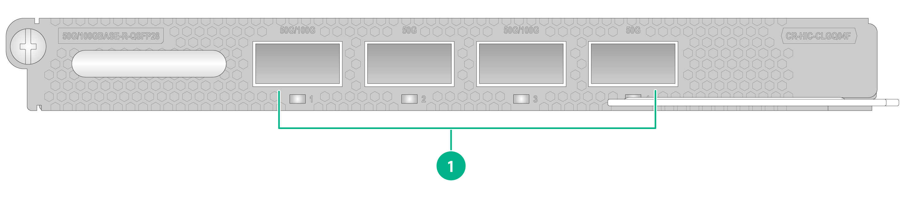
CR-HIC-CLGQ04F
Figure3-21 CR-HIC-CLGQ04F interface subcard LEDs
|
(1) 50G/100GBASE-R-QSFP28 port LEDs 1 to 4 (LINK/ACT) |
Table3-24 CR-HIC-CLGQ04F interface subcard LED descriptions
|
LED |
Status |
Description |
|
LINK/ACT (1 to 4) |
Off |
No link is present on the port. |
|
Steady green |
A link is present on the port. |
|
|
Flashing green |
The port is sending and receiving data. |
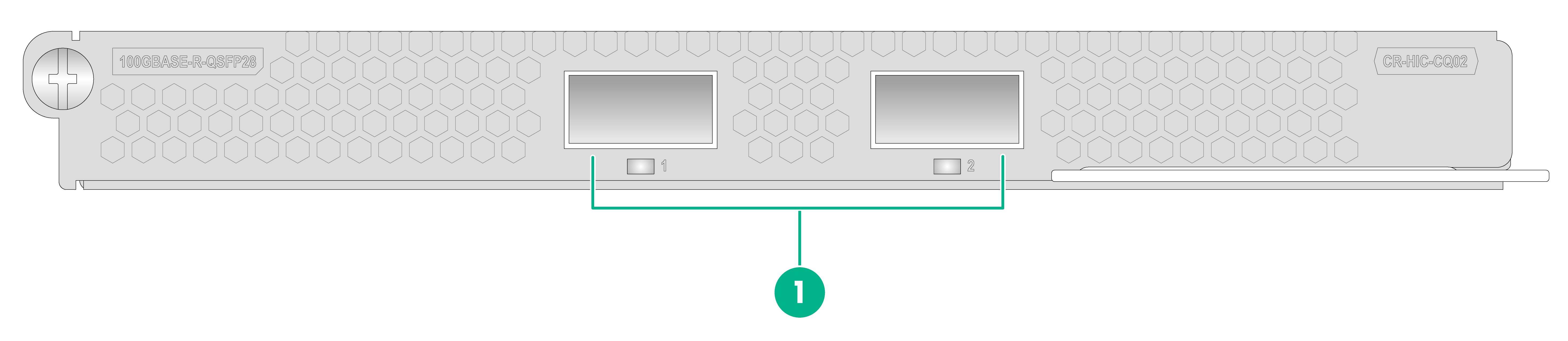
CR-HIC-CQ02
Figure3-22 CR-HIC-CQ02 interface subcard LEDs
|
(1) 100GBASE-R-QSFP28 port LEDs 1 and 2 (LINK/ACT) |
Table3-25 CR-HIC-CQ02 interface subcard LED descriptions
|
LED |
Status |
Description |
|
LINK/ACT (1 and 2) |
Off |
No link is present on the port. |
|
Steady green |
A link is present on the port. |
|
|
Flashing green |
The port is sending and receiving data. |
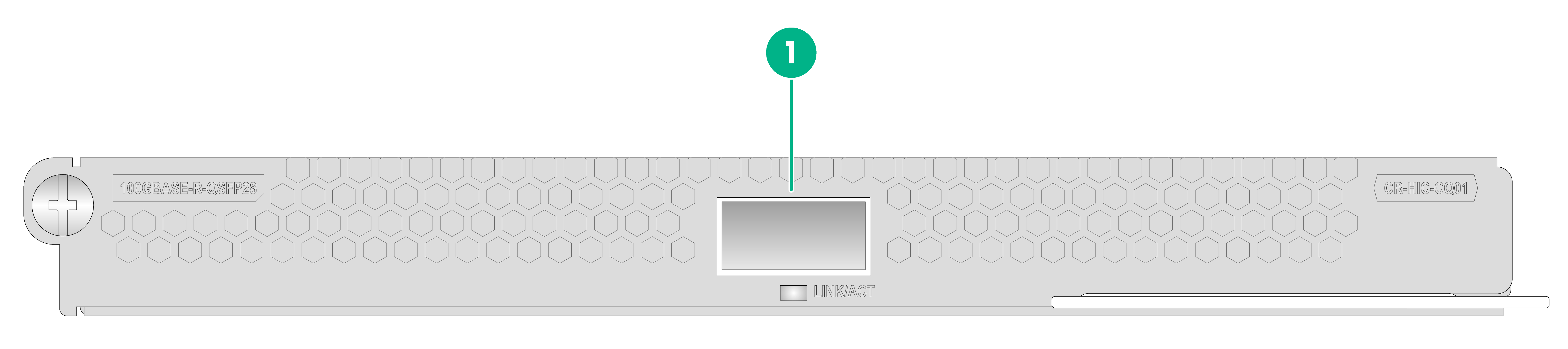
CR-HIC-CQ01
Figure3-23 CR-HIC-CQ01 interface subcard LEDs
|
(1) 100GBASE-R-QSFP28 port LED (LINK/ACT) |
Table3-26 CR-HIC-CQ01 interface subcard LED description
|
LED |
Status |
Description |
|
LINK/ACT |
Off |
No link is present on the port. |
|
Steady green |
A link is present on the port. |
|
|
Flashing green |
The port is sending and receiving data. |
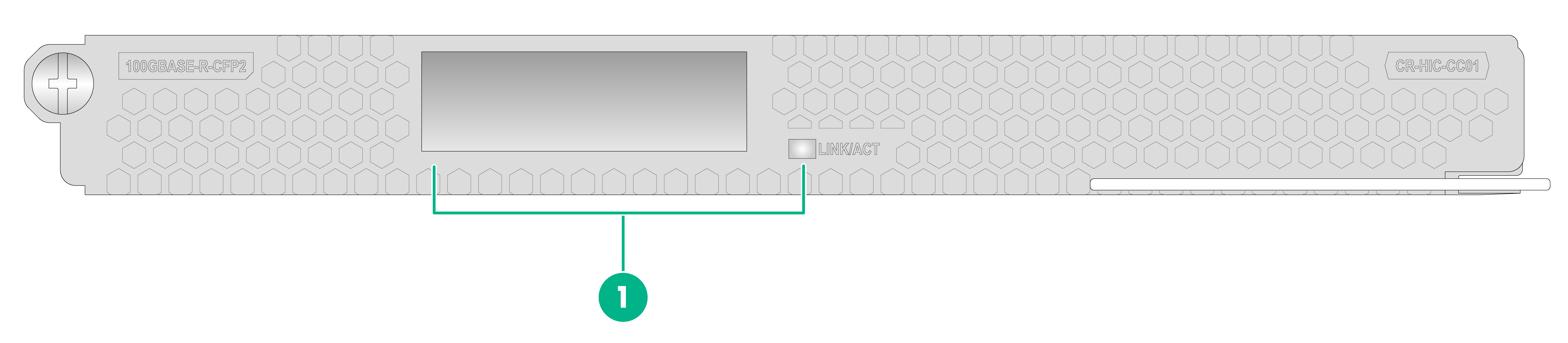
CR-HIC-CC01
Figure3-24 CR-HIC-CC01 interface subcard LEDs
|
(1) 100GBASE-R-CFP2 Ethernet port LED (LINK/ACT) |
Table3-27 CR-HIC-CC01 interface subcard LED description
|
LED |
Status |
Description |
|
LINK/ACT |
Off |
No link is present on the port. |
|
Steady green |
A link is present on the port. |
|
|
Flashing green |
The port is sending and receiving data. |
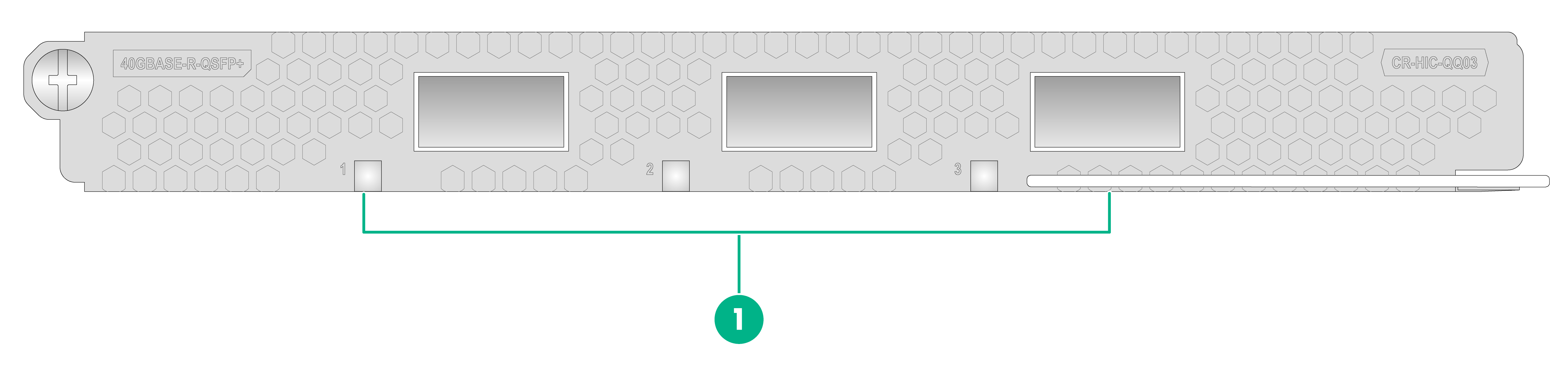
CR-HIC-QQ03
Figure3-25 CR-HIC-QQ03 interface subcard LEDs
|
(1) 40GBASE-R-QSFP+port LEDs 1 to 3 |
Table3-28 CR-HIC-QQ03 interface subcard LED description
|
LED |
Status |
Description |
|
LINK/ACT (1 to 3) |
Off |
No link is present on the port. |
|
Steady green |
A link is present on the port. |
|
|
Flashing green |
The port is sending and receiving data. |
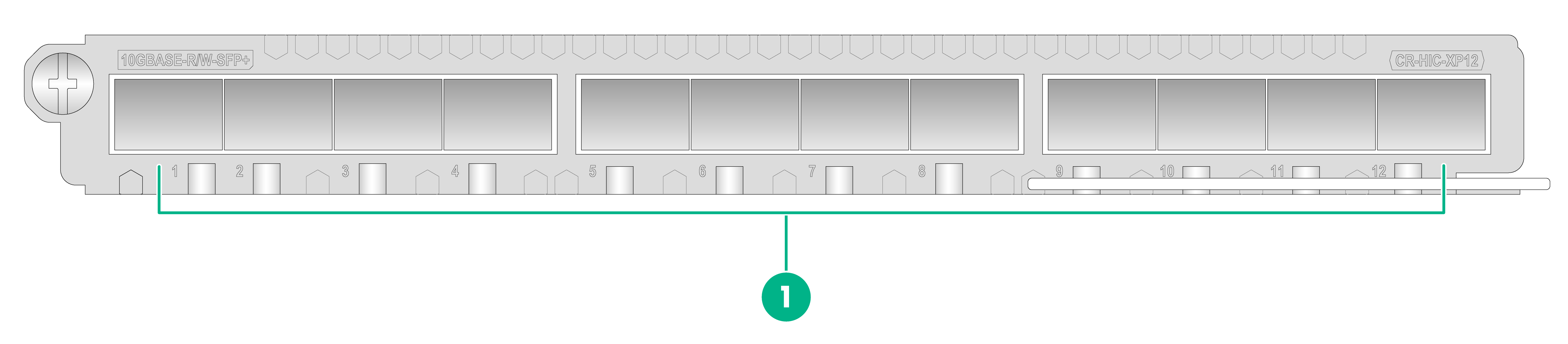
CR-HIC-XP12
Figure3-26 CR-HIC-XP12 interface subcard LEDs
|
(1) 10GBASE-R/W-SFP+ port LEDs 1 to 12 |
Table3-29 CR-HIC-XP12 interface subcard LED description
|
LED |
Status |
Description |
|
LINK/ACT (1 to 12) |
Off |
No link is present on the port. |
|
Steady green |
A link is present on the port. |
|
|
Flashing green |
The port is sending and receiving data. |
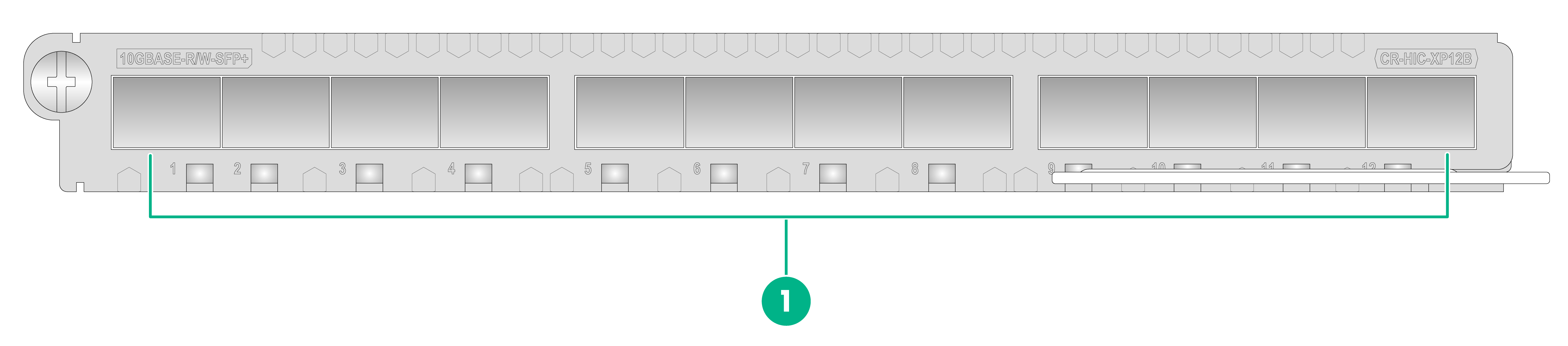
CR-HIC-XP12B
Figure3-27 CR-HIC-XP12B interface subcard LEDs
|
(1) 10GBASE-R/W-SFP+ port LEDs 1 to 12 |
Table3-30 CR-HIC-XP12B interface subcard LED descriptions
|
LED |
Status |
Description |
|
LINK/ACT (1 to 12) |
Off |
No link is present on the port. |
|
Steady green |
A link is present on the port. |
|
|
Flashing green |
The port is sending and receiving data. |
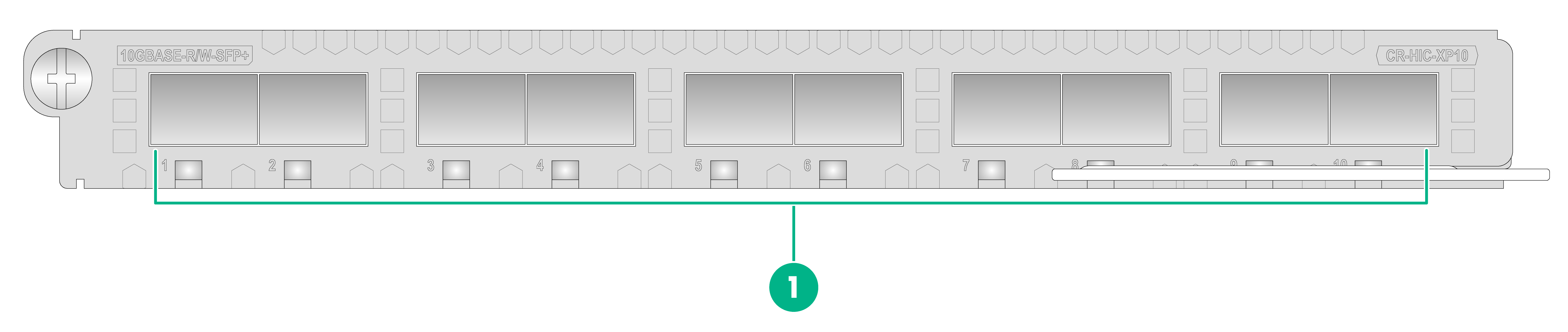
CR-HIC-XP10
Figure3-28 CR-HIC-XP10 interface subcard LEDs
|
(1) 1/10 GE port LEDs 1 to 10 |
Table3-31 CR-HIC-XP10 interface subcard LED description
|
LED |
Status |
Description |
|
LINK/ACT (1 to 10) |
Off |
No link is present on the port. |
|
Steady green |
A link is present on the port. |
|
|
Flashing green |
The port is sending and receiving data. |
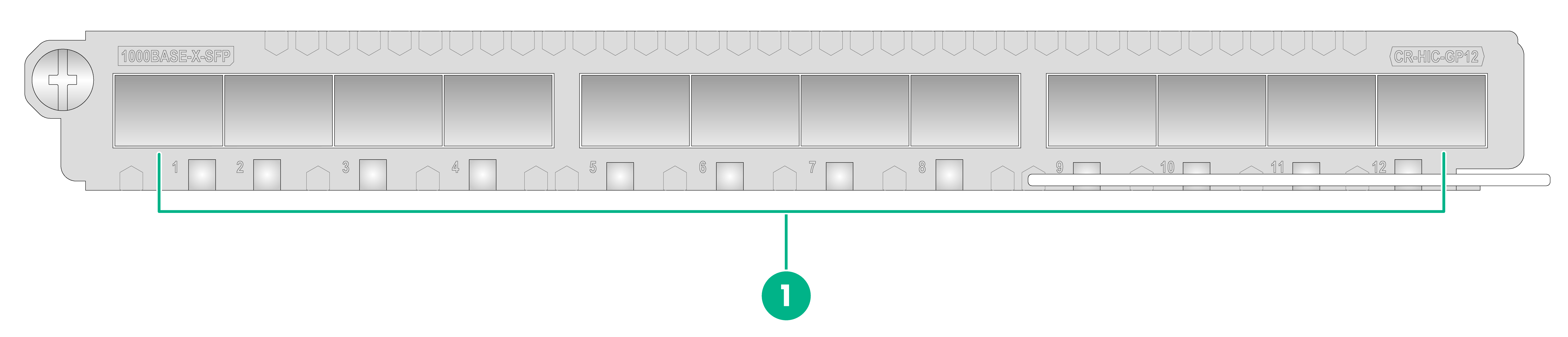
CR-HIC-GP12
Figure3-29 CR-HIC-GP12 interface subcard LEDs
|
(1) 1000BASE-X-SFP port LEDs 1 to 12 |
Table3-32 CR-HIC-GP12 interface subcard LED description
|
LED |
Status |
Description |
|
LINK/ACT (1 to 12) |
Off |
No link is present on the port. |
|
Steady green |
A link is present on the port. |
|
|
Flashing green |
The port is sending and receiving data. |
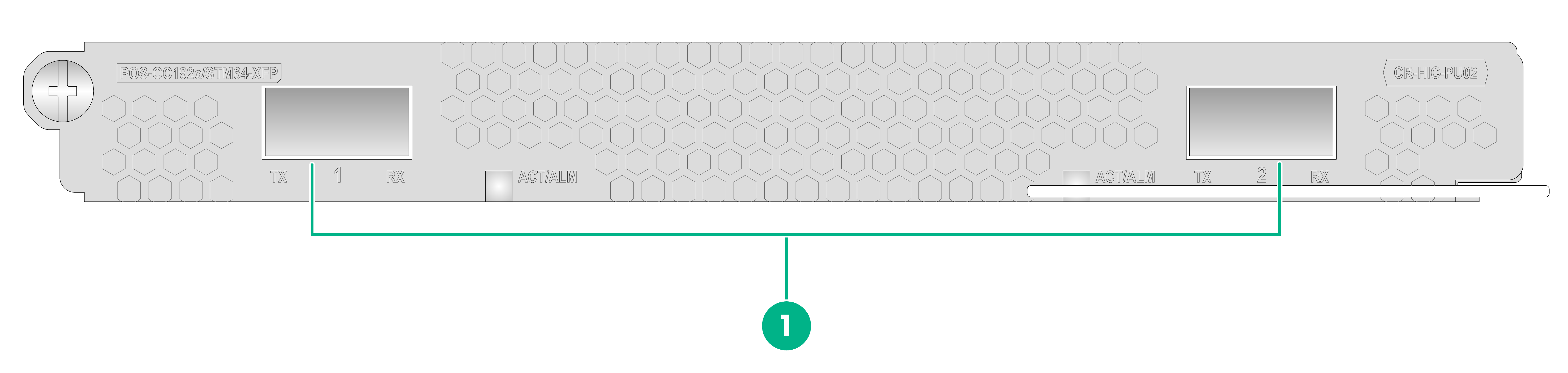
CR-HIC-PU02
Figure3-30 CR-HIC-PU02 interface subcard LEDs
|
(1) 10 GE POS-OC192c/STM64-XFP port LEDs 1 and 2 (ACT/ALM) |
Table3-33 CR-HIC-PU02 interface subcard LED description
|
LED |
Status |
Description |
|
ACT/ALM (1 and 2) |
Off |
The port is down. |
|
Steady green |
The port is up and is sending and receiving data correctly. |
|
|
Steady red |
A loss of signal (LOS) alarm has occurred on the port. |
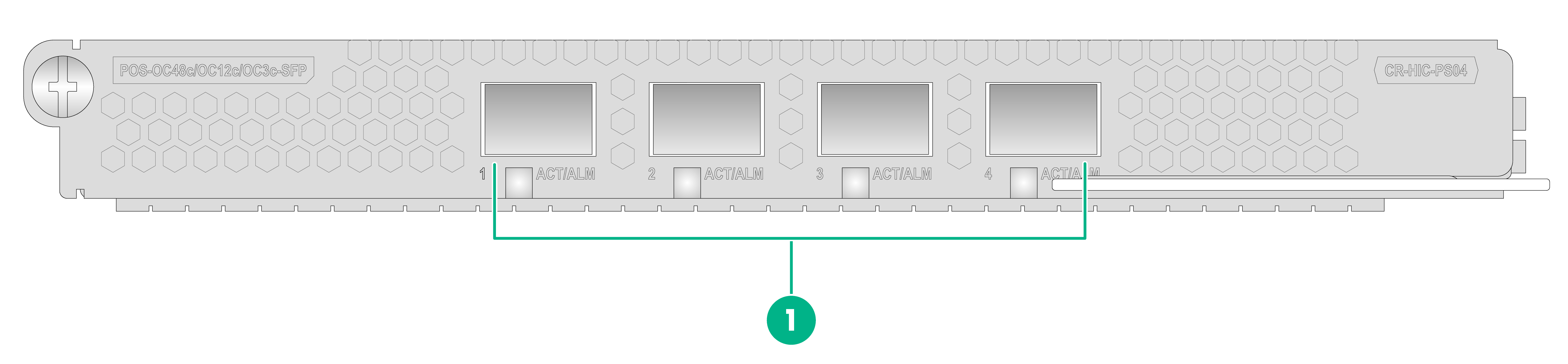
CR-HIC-PS04
Figure3-31 CR-HIC-PS04 interface subcard LEDs
|
(1) 155M/622M/2.5G POS port LEDs 1 to 4 (ACT/ALM) |
Table3-34 CR-HIC-PS04 interface subcard LED description
|
LED |
Status |
Description |
|
ACT/ALM (1 to 4) |
Off |
The port is down. |
|
Steady green |
The port is up and is sending and receiving data correctly. |
|
|
Steady red |
A LOS alarm has occurred on the port. |
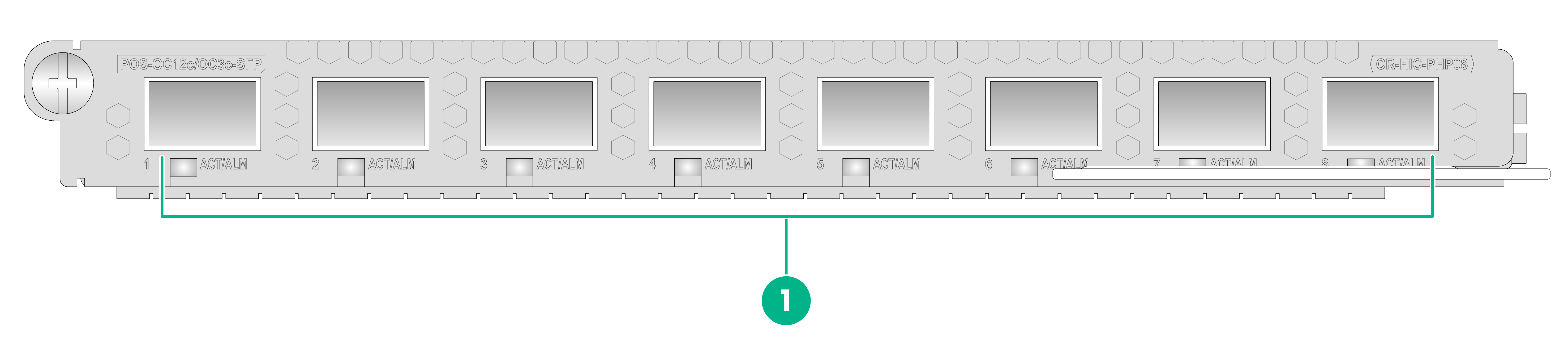
CR-HIC-PHP08
Figure3-32 CR-HIC-PHP08 interface subcard LEDs
|
(1) 155M/622M POS port LEDs 1 to 8 (ACT/ALM) |
Table3-35 CR-HIC-PHP08 interface subcard LED descriptions
|
LED |
Status |
Description |
|
ACT/ALM (1 to 8) |
Off |
The port is down. |
|
Steady green |
The port is up and is sending and receiving data correctly. |
|
|
Steady red |
A LOS alarm has occurred on the port. |
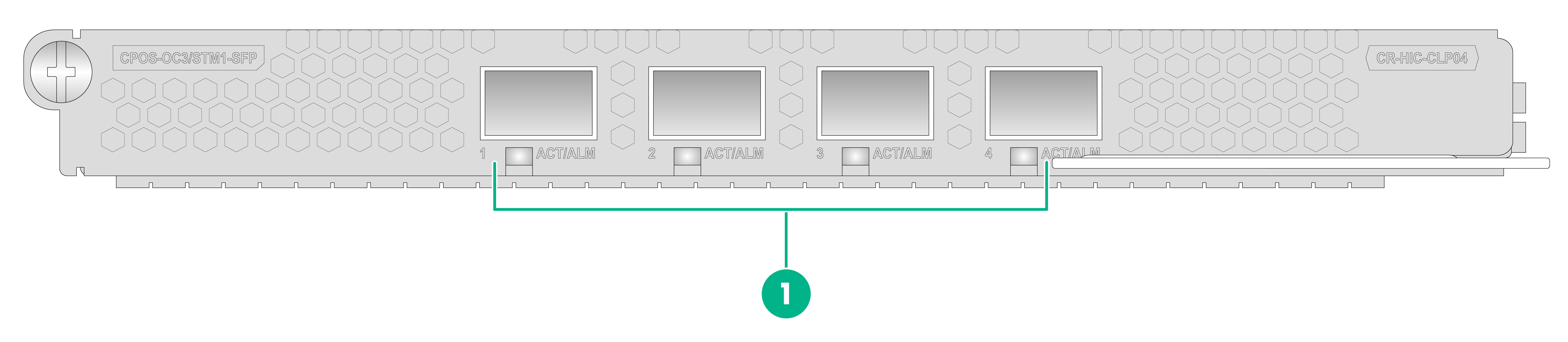
CR-HIC-CLP04
Figure3-33 CR-HIC-CLP04 interface subcard LEDs
|
(1) 155M CPOS port LEDs 1 to 4 (ACT/ALM) |
Table3-36 CR-HIC-CLP04 interface subcard LED descriptions
|
LED |
Status |
Description |
|
ACT/ALM (1 to 4) |
Off |
The port is down. |
|
Steady green |
The port is up but no data is transmitted on the port. |
|
|
Flashing green |
The port is up and is sending and receiving data correctly. |
|
|
Steady red |
An alarm has occurred on the port. |
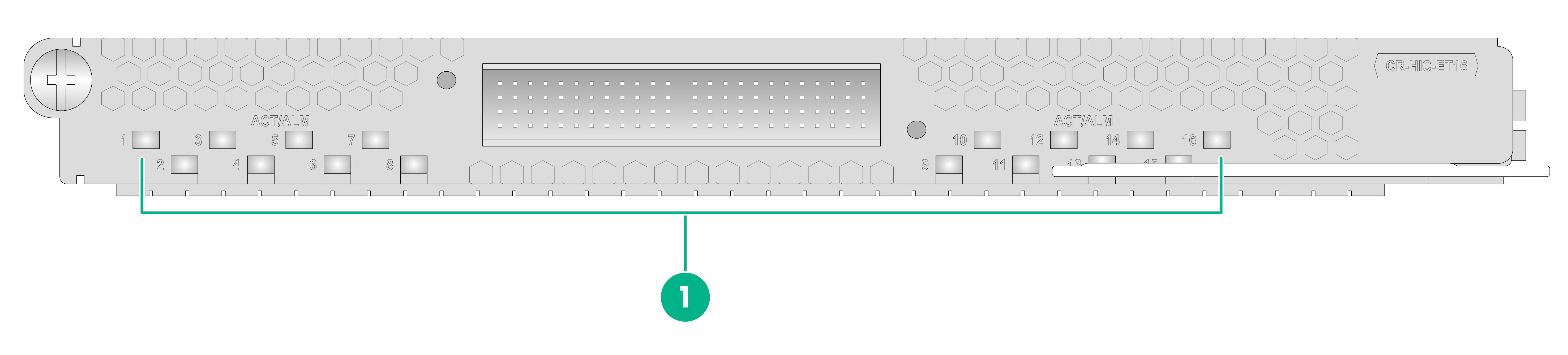
CR-HIC-ET16
Figure3-34 CR-HIC-ET16 interface subcard LEDs
|
(1) E1 port LEDs 1 to 16 (ACT/ALM) |
Table3-37 CR-HIC-ET16 interface subcard LED descriptions
|
LED |
Status |
Description |
|
ACT/ALM (1 to 16) |
Off |
The port is down. |
|
Steady green |
The port is up but no data is transmitted on the port. |
|
|
Flashing green |
The port is up and is sending and receiving data correctly. |
|
|
Steady red |
An alarm has occurred on the port. |
Power supply LEDs
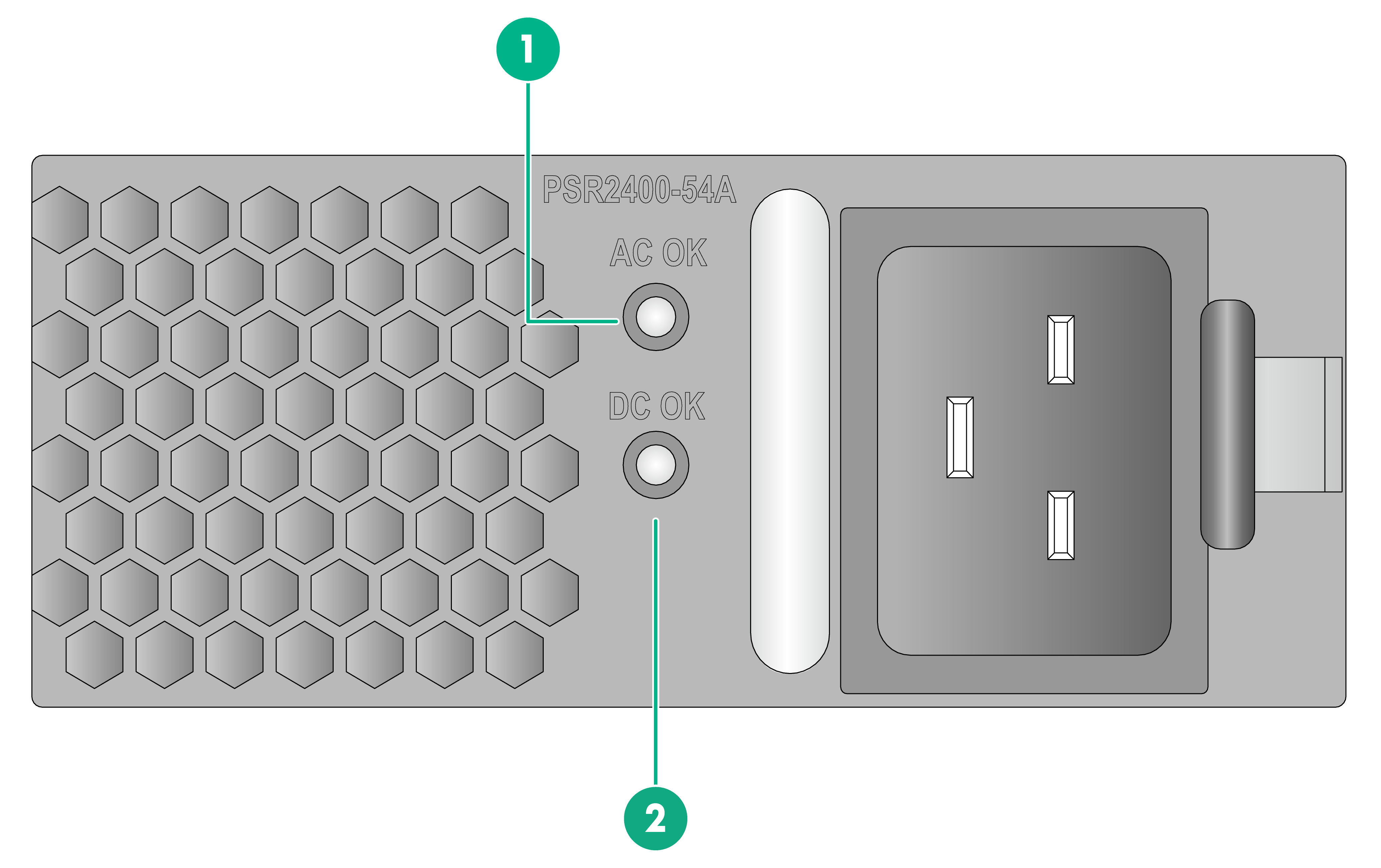
PSR2400-54A
Figure3-35 PSR2400-54A power supply LEDs
|
(1) Power input LED (AC OK) |
(2) Power output LED (DC OK) |
Table3-38 PSR2400-54A power supply LED description
|
LED |
Status |
Description |
|
AC OK DC OK |
AC OK: Steady green DC OK: Steady green |
The power supply is operating correctly. |
|
AC OK: Off DC OK: Steady red |
Abnormal power input. |
|
|
AC OK: Steady green DC OK: Steady red |
The power supply has entered output overvoltage, output overcurrent, or overtemperature protection state. |
|
|
AC OK: Steady green DC OK: Steady amber |
An overtemperature alarm has occurred. |
|
|
AC OK: Off DC OK: Off |
No power input. |
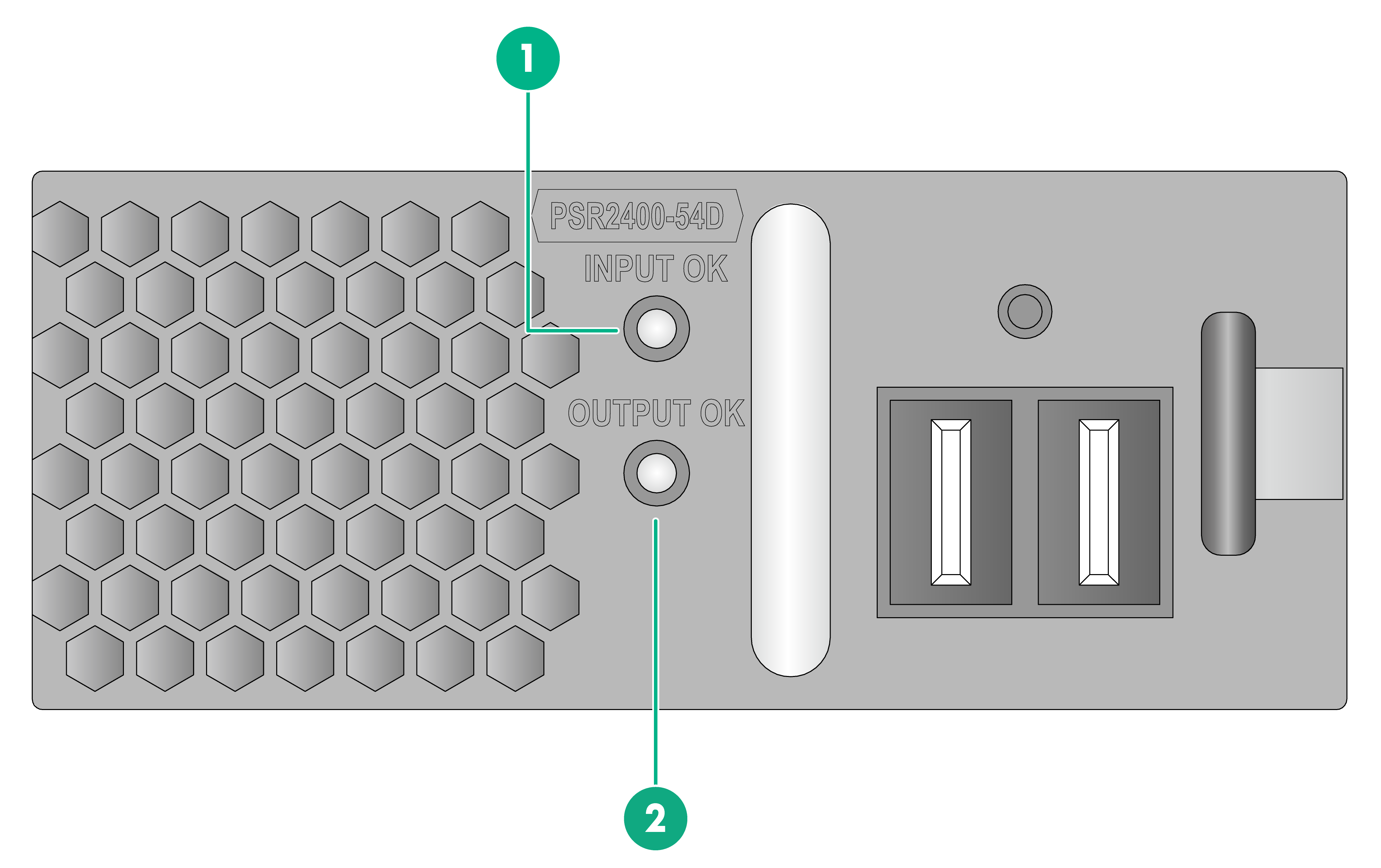
PSR2400-54D
Figure3-36 PSR2400-54D power supply LEDs
|
(1) Power input LED (INPUT OK) |
(2) Power output LED (OUTPUT OK) |
Table3-39 PSR2400-54D DC power supply LED description
|
LED |
Status |
Description |
|
INPUT OK OUTPUT OK |
INPUT OK: Steady green OUTPUT OK: Steady green |
The power supply is operating correctly. |
|
INPUT OK: Off OUTPUT OK: Steady red |
Abnormal power input. |
|
|
INPUT OK: Steady green OUTPUT OK: Steady red |
The power supply has entered output overvoltage, output overcurrent, or overtemperature protection state. |
|
|
INPUT OK: Steady green OUTPUT OK: Steady amber |
An overtemperature alarm has occurred. |
|
|
INPUT OK: Off OUTPUT OK: Off |
No power input. |
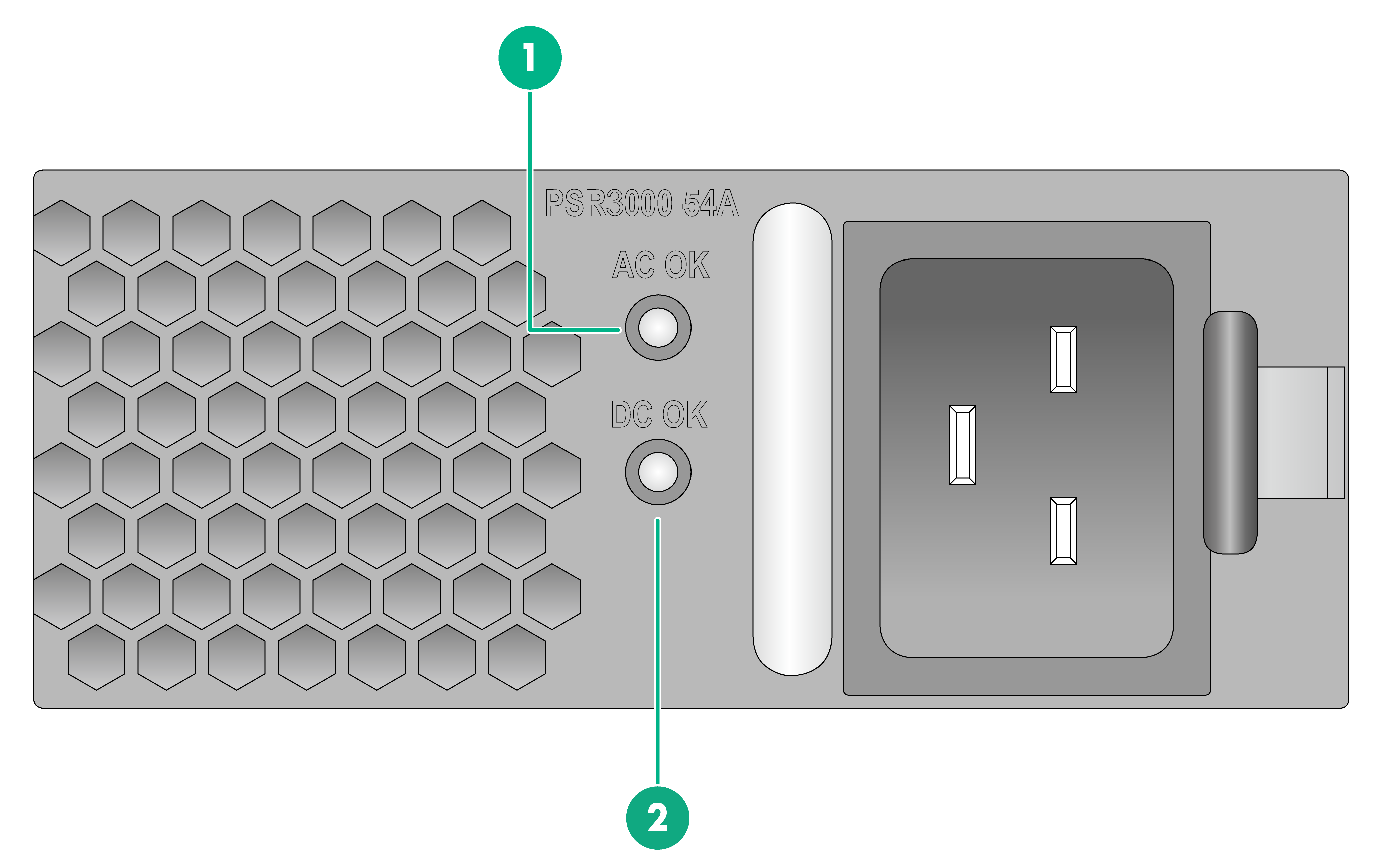
PSR3000-54A
Figure3-37 PSR3000-54A power supply LEDs
|
(1) Power input LED (AC OK) |
(2) Power output LED (DC OK) |
Table3-40 PSR3000-54A power supply LED description
|
LED |
Status |
Description |
|
AC OK DC OK |
AC OK: Steady green DC OK: Steady green |
The power supply is operating correctly. |
|
AC OK: Off DC OK: Steady red |
Abnormal power input. |
|
|
AC OK: Steady green DC OK: Steady red |
The power supply has entered output overvoltage, output overcurrent, or overtemperature protection state. |
|
|
AC OK: Steady green DC OK: Steady amber |
An overtemperature alarm has occurred. |
|
|
AC OK: Off DC OK: Off |
No power input. |
Fan tray LEDs
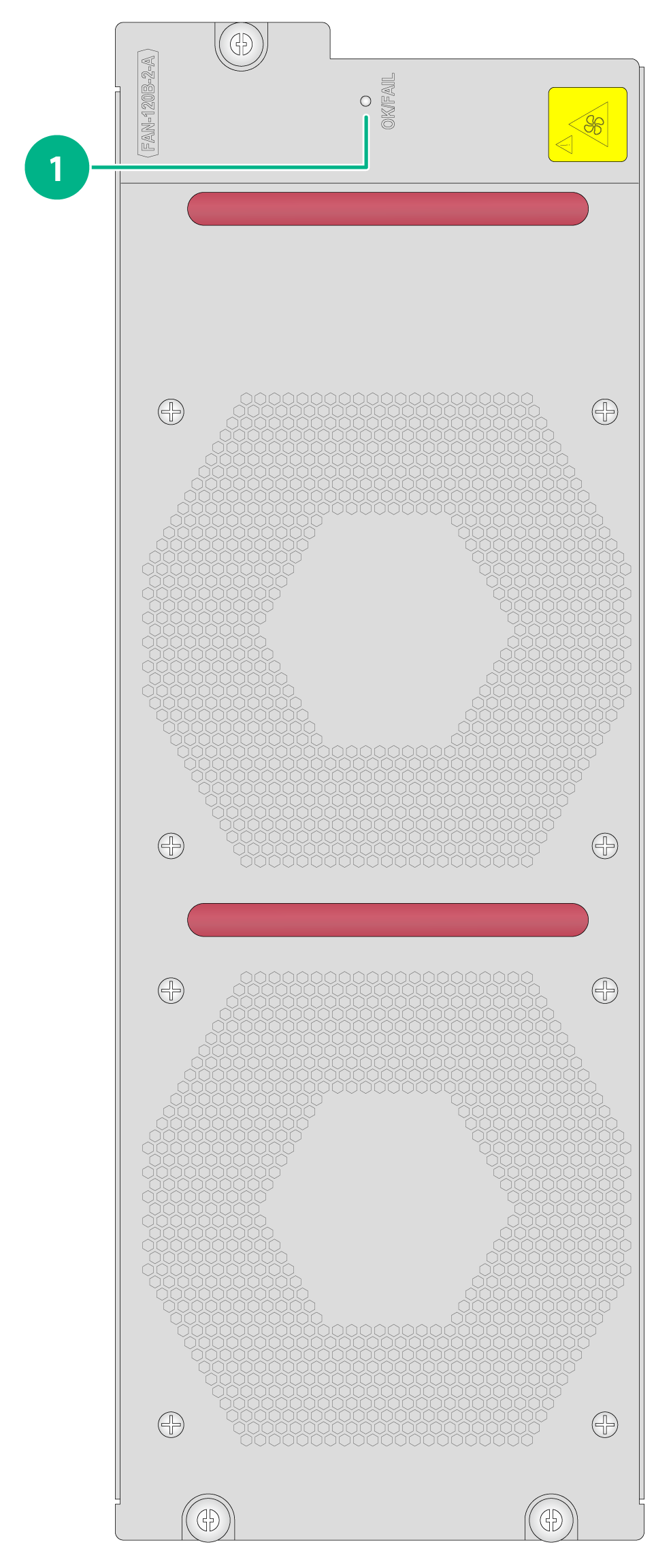
The FAN-120B-2-A fan trays are available for the router. This fan tray provides an OK/FAIL LED to indicate its operating status.
Figure3-38 FAN-120B-2-A fan tray LEDs
|
(1) Fan tray status LED (OK/FAIL) |
Table3-41 FAN-120B-2-A fan tray LED description
|
LED |
Status |
Description |
|
OK/FAIL |
Steady green |
The fan tray is in normal state. |
|
Steady red |
The fan tray is faulty. |
|
|
Off |
The fan tray is faulty or not fully inserted. |
FRU specifications
MPUs
Table3-42 describes the MPUs available for the router.
Table3-42 MPUs available for the router and port types
|
Models |
Port type |
|
CR-19K-MPU-08A |
· 1 × serial console port · 1 × mini-USB console port (Type mini-B) · 2 × 10/100/1000BASE-T ports · 2 × 1000BASE-X-SFP ports · 1 × USB 2.0 port (Type A, host mode) |
|
CR-19K-MPU-08B |
· 1 × serial console port (RJ-45) · 1 × USB console port (Type C) · 1 × USB 2.0 port (Type A, host mode) · 2 × management ports: ¡ 1 × 10/100/1000BASE-T port ¡ 1 × 1000BASE-X-SFP port · 2 × 1000BASE-X-SFP ports · 2 × 1PPS/ToD time synchronization ports · 2 × SMB clock input ports · 2 × SMB clock output ports |
Fabric modules
Table3-43 describes the fabric modules available for the router.
Table3-43 Fabric modules available for the router and port types
|
Models |
Port type |
|
CR-19K-SFU-08C |
N/A |
|
CR-19K-MSFU-08A |
6 × cluster ports (QSFP+/QSFP28) |
Interface modules
Table3-44 describes the interface modules available for the router.
Table3-44 Interface modules available for the router and their specifications
|
Interface module model |
Description |
Connector type |
Port type and quantity |
Port speed |
|
CR-19K-LPU-CQ18 |
H3C CR 18-port 100G QSFP28 Ethernet optical interface module |
· MPO · LC |
18 × 100GBASE-R-QSFP28 fiber ports |
103.125 Gbps |
|
CR-19K-LPU-CQ12 |
H3C CR 12-port 100G QSFP28 Ethernet optical interface module |
· MPO · LC |
12 × 100GBASE-R-QSFP28 fiber ports |
103.125 Gbps |
|
CR-19K-LPU-CQ12B |
H3C CR 12-port 100G QSFP28 Ethernet optical interface module |
· MPO · LC |
12 × 100GBASE-R-QSFP28 fiber ports |
103.125 Gbps |
|
CR-19K-LPU-CQ06B |
H3C CR 6-port 100G QSFP28 Ethernet optical interface module B |
· MPO · LC |
6 × 100GBASE-R-QSFP28 fiber ports |
103.125 Gbps |
|
CR-19K-LPU-CC08 |
H3C CR 8-port 100G CFP2 Ethernet optical interface module |
· MPO · LC |
8 × 100GBASE-R-CFP2 fiber ports |
103.125 Gbps |
|
CR-19K-LPU-CC04 |
H3C CR 4-port 100G CFP2 Ethernet optical interface module |
· MPO · LC |
4 × 100GBASE-R-CFP2 fiber ports |
103.125 Gbps |
|
CR-19K-LPU-CC04B |
H3C CR 4-port 100G CFP2 Ethernet optical interface module B |
· MPO · LC |
4 × 100GBASE-R-CFP2 fiber ports |
103.125 Gbps |
|
CR-19K-LPU-XP72 |
H3C CR 72-port 10G SFP+ Ethernet optical interface module |
LC |
72 × 10GBASE-R/W-SFP+ fiber ports |
· LAN: 10.3125 Gbps · WAN: 9.95328 Gbps |
|
CR-19K-LPU-XP48 |
H3C CR 48-port 10G SFP+ Ethernet optical interface module |
LC |
48 × 10GBASE-R/W-SFP+ fiber ports |
· LAN: 10.3125 Gbps · WAN: 9.95328 Gbps |
|
CR-19K-LPU-XP40 |
H3C CR 40-port 10G SFP+ Ethernet optical interface module |
LC |
40 × 10GBASE-R/W-SFP+ fiber ports |
· LAN: 10.3125 Gbps · WAN: 9.95328 Gbps |
|
CR-19K-LPU-XP20CC02 |
H3C CR 20-port 10G SFP+ + 2-port 100G CFP2 Ethernet optical interface module |
· MPO · LC |
20 × 10GBASE-R/W-SFP+ fiber ports and 2 × 100GBASE-R-CFP2 fiber ports |
· SFP+ port: ¡ LAN: 10.3125 Gbps ¡ WAN: 9.95328 Gbps · CFP2 port: 103.125 Gbps |
|
CR-19K-LPU-8004 |
H3C CR 800G flexible interface module |
N/A |
4 × interface subcard slots |
N/A |
|
CR-19K-LPU-4004 |
H3C CR 400G flexible interface module |
N/A |
4 × interface subcard slots |
N/A |
|
CR-19K-LPU-2002 |
H3C CR 200G flexible interface module |
N/A |
2 × interface subcard slots |
N/A |
|
CR-19K-LPU-2002B |
H3C CR 200G flexible interface module B |
N/A |
2 × interface subcard slots |
N/A |
|
CR-19K-LPU-SP |
H3C CR flexible service processing module |
N/A |
N/A |
N/A |
Interface subcards
Table3-45 describes the interface subcards available for the router.
Table3-45 Interface subcards available for the router and their specifications
|
Interface subcard model |
Description |
Connector type |
Port type and quantity |
Port speed |
|
CR-HIC-CLGQ04F |
4-port 50G/2-port 100G QSFP28 Ethernet optical interface subcard |
· MPO · LC |
4 × 50GBASE-R-QSFP28 ports or 2 × 100GBASE-R-QSFP28 ports |
53.125/103.125 Gbps |
|
CR-HIC-CQ02 |
2-port 100G QSFP28 Ethernet optical interface subcard |
· MPO · LC |
2 × 100GBASE-R-QSFP28 ports |
103.125 Gbps |
|
CR-HIC-CQ01 |
1-port 100G QSFP28 Ethernet optical interface subcard |
· MPO · LC |
1 × 100GBASE-R-QSFP28 port |
103.125 Gbps |
|
CR-HIC-CC01 |
1-port 100G CFP2 Ethernet optical interface subcard |
· MPO · LC |
1 × 100GBASE-R-CFP2 port |
103.125 Gbps |
|
CR-HIC-QQ03 |
3-port 40G QSFP+ Ethernet optical interface subcard |
· MPO · LC |
3 × 40GBASE-R-QSFP+ ports |
41.25 Gbps |
|
CR-HIC-XP12 |
12-port 10G SFP+ Ethernet optical interface subcard |
LC |
12 × 10GBASE-R/W-SFP+ ports |
· LAN: 10.3125 Gbps · WAN: 9.95328 Gbps |
|
CR-HIC-XP12B |
12-port 10G SFP+ Ethernet optical interface subcard |
LC |
12 × 10GBASE-R/W-SFP+ ports |
· LAN: 10.3125 Gbps · WAN: 9.95328 Gbps |
|
CR-HIC-XP10 |
10-port 1G SFP/10G SFP+ Ethernet optical interface subcard |
LC |
10 × 1000BASE-X-SFP or 10GBASE-R/W-SFP+ ports |
· SFP port: 1.25 Gbps · SFP+ port: ¡ LAN: 10.3125 Gbps ¡ WAN: 9.95328 Gbps |
|
CR-HIC-GP12 |
12-port GE SFP Ethernet optical interface subcard |
LC |
12 × 1000BASE-X-SFP ports |
1.25 Gbps |
|
CR-HIC-PU02 |
2-port 10G POS XFP optical interface subcard |
LC |
2 × 10G POS XFP ports |
9.95328 Gbps |
|
CR-HIC-PS04 |
4-port 155M/622M/2.5G POS SFP optical interface subcard |
LC |
4 × 155M/622M/2.5G POS SFP ports |
155.52/622.08/2488.32 Mbps |
|
CR-HIC-PHP08 |
8-port 155M/622M POS SFP optical interface subcard |
LC |
8 × 155M/622M POS SFP ports |
155.52/622.08 Mbps |
|
CR-HIC-CLP04 |
4-port 155M CPOS SFP optical interface subcard |
LC |
4 × 155M CPOS SFP ports |
155.52 Mbps |
|
CR-HIC-ET16 |
16-port E1 copper interface subcard (HM96 male connector) |
HM96 |
16 × E1 ports |
2.048 Mbps |
Power supplies
The PSR2400-54A, PSR2400-54D, and PSR3000-54A power supplies are available for the router.
The PSR2400-54A is an AC input and DC output power supply. The PSR2400-54D is a DC input and DC output power supply. They provide a maximum output of 2400 W.
The PSR3000-54A is an AC input and DC output power supply. It provides a maximum output power of 3000 W.
Table3-46 describes the specifications of the power supplies available for the router.
Table3-46 Power supply specifications
|
Item |
PSR2400-54A |
PSR2400-54D |
PSR3000-54A |
|
Rated input voltage |
· 100 to 130 VAC @ 60 Hz · 200 to 240 VAC @ 50 Hz · 240 VDC |
–48 to –60 VDC |
· 100 to 130 VAC @ 60 Hz · 200 to 240 VAC @ 50 Hz · 240 VDC |
|
Max. input voltage |
· 90 to 264 VAC @ 47 to 63 Hz · 190 to 320 VDC |
–40 to –72 VDC |
· 90 to 290 VAC @ 47 to 63 Hz · 190 to 320 VDC |
|
Max. input current |
16 A |
80 A |
16 A |
|
Rated output voltage |
54 VDC |
54 VDC |
54 VDC |
|
Max. output current |
44.5 A |
44.5 A |
55.6 A |
|
Max. output power |
· 100 to 130 VAC @ 60 Hz: 1200 W · 200 to 240 VAC @ 50 Hz: 2400 W · 240 VDC: 2400 W |
2400 W |
· 100 to 130 VAC @ 60 Hz: 1200 W · 200 to 240 VAC @ 50 Hz: 3000 W · 240 VDC: 3000 W |
|
Ambient temperature |
· Operating: –10°C to +50°C (14°F to 122°F) · Storage: –40°C to +70°C (–40°F to +158°F) |
· Operating: –10°C to +50°C (14°F to 122°F) · Storage: –40°C to +70°C (–40°F to +158°F) |
· Operating: –10°C to +50°C (14°F to 122°F) · Storage: –40°C to +70°C (–40°F to +158°F) |
Fan trays
The router uses six fan trays. The FAN-120B-2-A fan trays are available for the router.
Table3-47 FAN-120B-2-A fan tray specifications
|
Item |
Specifications |
|
Diameter |
120 mm (4.72 in) |
|
Number of fans |
2 |
|
Max fan speed |
12000 RPM |
|
Max air volume |
580 CFM |
