- Table of Contents
- Related Documents
-
| Title | Size | Download |
|---|---|---|
| 01-About the Router | 1.55 MB |
Contents
1 About the router
Unless otherwise stated, MPUs, fabric modules, and interface modules are collectively referred to as "modules" in this document.
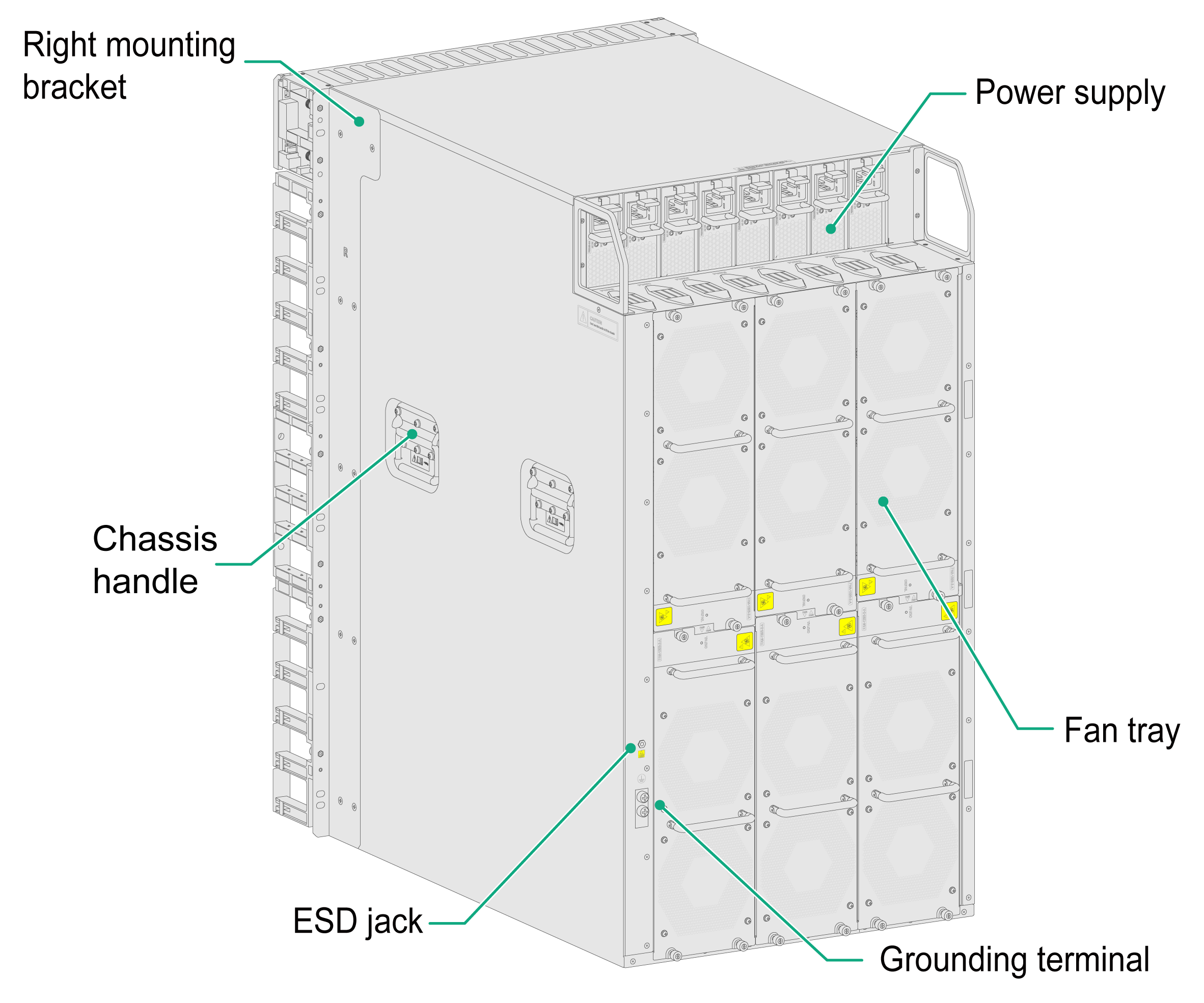
Chassis views
Figure1-1 Front view
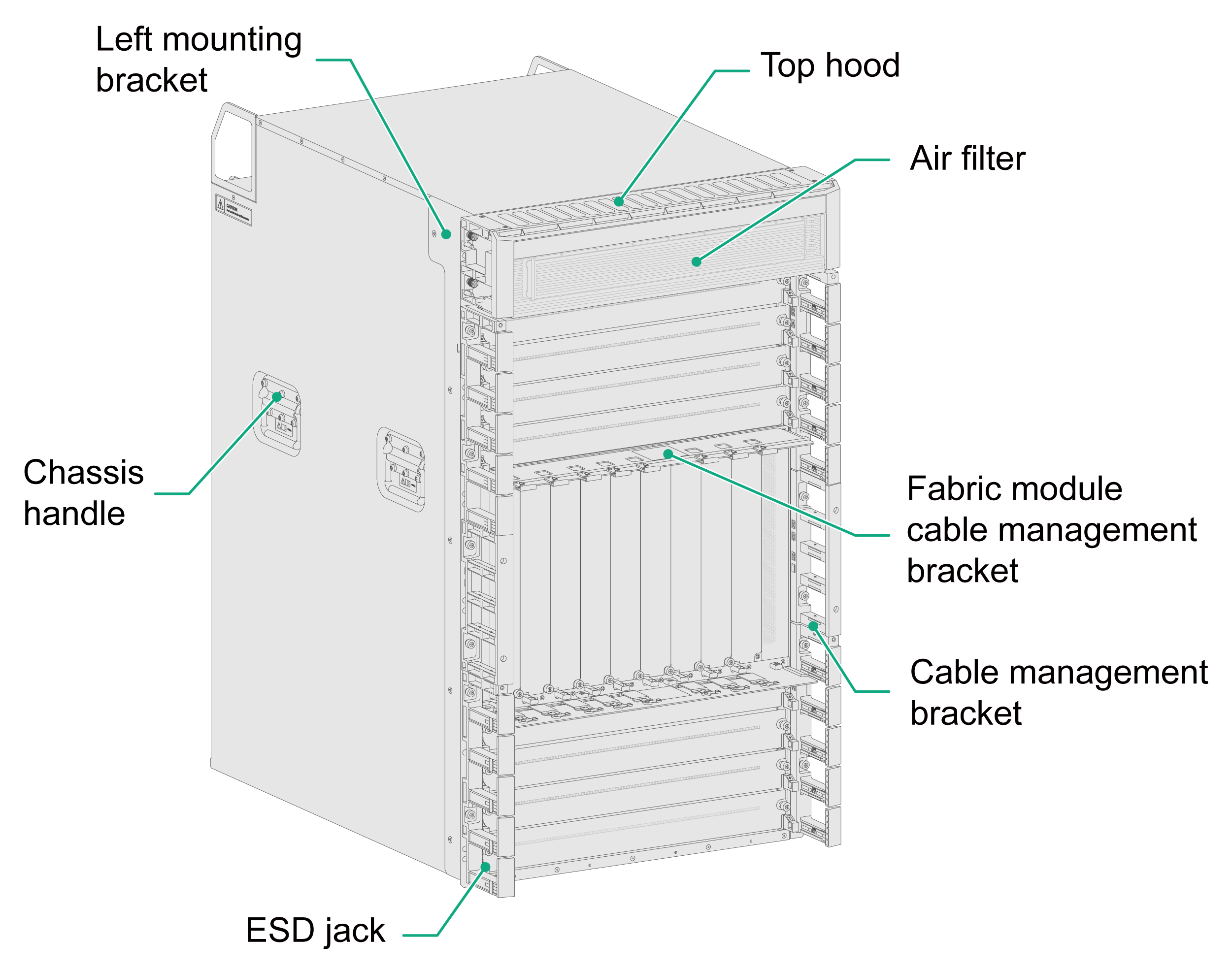
Figure1-2 Rear view
Slot arrangement
The router has an MPU section, fabric module section, interface module section, power supply section, and fan tray section.
"LPU" in Figure1-3 refers to an interface module, "SFU" refers to a single-chassis fabric module, and "MSFU" refers to a multi-chassis fabric module.

Table1-1 Descriptions for the router sections
|
Section |
Slots |
Description |
|
MPU section |
2 (slots 8 and 9) |
No MPUs are provided with the router. Purchase MPUs yourself. You can install one MPU, or two MPUs for redundancy for the router. To install one MPU for the router, you can install it in either of the MPU slots. |
|
Fabric module section |
6 (slots 10 to 15) |
No fabric modules are provided with the router. Purchase fabric modules yourself. |
|
Interface module section |
8 (slots 0 to 3 and slots 4 to 7) |
No interface modules are provided with the router. Purchase interface modules yourself. |
|
Power supply section |
8 (slots PWR 1 to PWR 8) |
No power supplies are provided with the router. Purchase power supplies yourself. The power supplies are at the rear of the chassis. |
|
Fan tray section |
6 (slots FAN 1 to FAN 6) |
The router is shipped with a fan tray in each fan tray slot. The fan trays are at the rear of the chassis. |
Technical specifications
|
Description |
|
|
Dimensions (H × W × D) |
843 × 440 × 650 mm (33.19 × 17.32 × 25.59 in) (19 RUs) |
|
Shipping weight |
115.0 kg (253.53 lb) |
|
Weight (chassis with mounting brackets and filler panels) |
86.8 kg (191.36 lb) |
|
Weight (fully configured) |
230.0 kg (507.05 lb) |
|
Router weight |
Chassis weight (including mounting brackets and filler panels) plus removable component weight (including modules, power supplies, fan trays, and other removable components) |
|
System power consumption |
Sum of the power consumption of all modules and the power consumption of all configured fan trays |
|
Heat dissipation (per hour) |
0.9 × (power consumption of all modules plus power consumption of all configured fan trays)/0.9 × 3.4121 |
|
Sound pressure level (fully configured with six fan trays) in the acceptable temperature ranges |
≤ 61.2 dBA |
|
Rack |
· Recommended: A minimum of 1000 mm (39.37 in) in depth · Optional: 800 mm (31.50 in) in depth. Thickness of the door must be less than 25 mm (0.98 in) |
|
Slide |
· LSXM1BSR—Applicable to a rack with a depth of more than 1000 mm (39.37 in) · LSTM2KSGD0—Applicable to a rack with a depth of 800 mm (31.50 in) · LSTM1KSGD0—Applicable to a rack with a depth of 800 mm (31.50 in) |
|
Temperature |
· Operating: 0°C to 45°C (32°F to 113°F) · Storage: –40°C to +70°C (–40°F to +158°F) |
|
Relative humidity |
· Operating: 5% RH to 95% RH (noncondensing) · Storage: 5% RH to 95% RH (noncondensing) |
|
|
NOTE: · Rack height is measured in RUs. One RU is 44.45 mm (1.75 in). · Dimensions in the table are for the chassis only, excluding the mounting brackets, cable management brackets, modules, and power supplies. · Heat dissipation is measured in BTU/h. 1 W equals 3.4121 BTU/h. · The sound pressure levels are measured based on the method specified in ISO 7779 at bystander positions. |
Interface numbering
Conventions
|
|
IMPORTANT: The two management ports on the MPU are numbered 1/0/0/0 and 1/0/0/1. |
The interfaces on the router are numbered in the interface-type W/X/Y/Z format.
Where,
· interface-type—Interface type, for example, Gigabit Ethernet.
· W—Chassis ID of the router in the cluster. In single-chassis mode, the number is 1. In back-to-back cluster mode, the numbers are 1 and 2.
· X—Number of the slot where the module resides, as shown by the number in Figure1-3.
· Y—The number depends on the interface module type.
¡ CR-19K-LPU-2002, CR-19K-LPU-2002B, CR-19K-LPU-4004, or CR-19K-LPU-8004 interface module—Number of the slot where the interface subcard resides on the interface module.
¡ Interface modules other than CR-19K-LPU-2002, CR-19K-LPU-2002B, CR-19K-LPU-4004, and CR-19K-LPU-8004—0.
· Z—Number of the interface on the interface subcard or interface module.
Example
The router is in single-chassis mode. A CR-HIC-GP12 interface subcard is installed on a CR-19K-LPU-4004 interface module in slot 3 of the router.
· If the CR-HIC-GP12 subcard is installed in slot 1 of the CR-19K-LPU-4004 interface module, the Gigabit Ethernet ports 1 to 12 on the CR-HIC-GP12 subcard are numbered GigabitEthernet 1/3/1/1 to GigabitEthernet 1/3/1/12, respectively.
· If the CR-HIC-GP12 subcard is installed in slot 2 of the CR-19K-LPU-4004 interface module, the Gigabit Ethernet ports 1 to 12 on the CR-HIC-GP12 subcard are numbered GigabitEthernet 1/3/2/1 to GigabitEthernet 1/3/2/12, respectively.
