- Table of Contents
-
- H3C S12500X-AF Switch Series Installation Guide-6W115
- 00-Preface
- 01-Chapter 1 Preparing for Installation
- 02-Chapter 2 Installing the Switch
- 03-Chapter 3 Installing FRUs
- 04-Chapter 4 Setting Up an IRF Fabric
- 05-Chapter 5 Connecting Your Switch to the Network
- 06-Chapter 6 Troubleshooting
- 07-Chapter 7 Replacement Procedures
- 08-Appendix A Engineering labels
- 09-Appendix B Cabling Recommendations
- 10-Appendix C Repackaging the Switch
| Title | Size | Download |
|---|---|---|
| 07-Chapter 7 Replacement Procedures | 3.23 MB |
Contents
(Optional) Removing an interface module adapter
(Optional) Removing an LPU protective blank panel
Replacing a switching fabric module
Replacing a transceiver module
Replacing a CFP2 transceiver module
Replacing an SFP+/SFP/QSFP+/QSFP28/QSFP-DD transceiver module
Replacing a CXP transceiver module
Replacing an SFP+/QSFP+/QSFP28/QSFP-DD/QSFP+ to SFP+ copper cable
7 Replacement procedures
|
|
CAUTION: · When replacing FRUs while the switch is operating, ensure electrical safety. · Follow the replacement procedures strictly to avoid bodily injury and device damage. · Long-time exposure to strong air flow might cause discomfort. To avoid this hazard, do not stand close to the air outlet vents while the switch is operating. If you must be next to the switch on the air outlet vent side for an extended period, avoid the air flow or take other protective measures. |
The switch uses a modular, hot-swappable architecture, and supports field replaceable units (FRUs). You can replace the FRUs when the switch is operating.
Replacing a power module
|
|
CAUTION: · Provide a circuit breaker for each power module. Before replacing a power module, turn off its circuit breaker. · The power module might be of high temperature. Remove it with caution. · To install the removed power module in the chassis again, install it after the status LED on it is off. |
Strictly follow the procedures shown in Figure7-1 and Figure7-2 to replace a power module to avoid device damage and bodily injury.
Figure7-1 Power module removal procedure
![]()
Figure7-2 Power module installation procedure
![]()
To replace a power module:
1. Prepare an antistatic mat to place the removed power module.
2. Turn off the circuit breaker.
3. Wear an ESD wrist strap, and make sure it makes good skin contact and is reliably grounded. For more information, see "Installing FRUs."
4. Remove the power cord.
¡ For an AC power module, remove the cable tie, and then remove the power cord connector from the power module.
¡ For a DC power module, loosen the screw on the power cord connector, and then remove the connector from the power module.
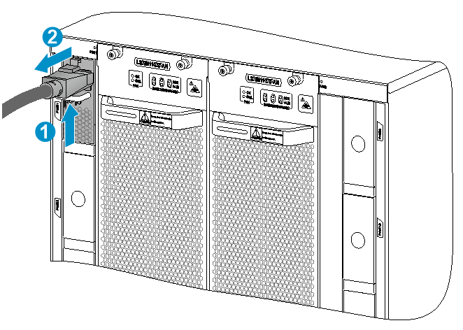
¡ For a PSR3000-54AHD power module, pressing the release latch on the power cord connector with your forefinger of one hand (see callout 1) and squeezing the connector with your forefinger and thumb of the other hand (see callout 2), pull out the power cord from the power module, as shown in Figure7-3.
Figure7-3 Removing the power cord from a PSR3000-54AHD power module
|
(1) Press the release latch on the connector |
|
(2) Pull the connector out of the power module |
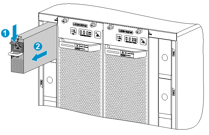
5. Press the latch on the power module to the handle direction and pull the power module part way out of the slot.
6. Holding the power module handle with one hand and supporting the power module bottom with another, pull the power module slowly out of the slot.
7. Place the removed power module on the antistatic mat.
8. Install a new power module. For information about the power module installation procedure, see "Installing FRUs."
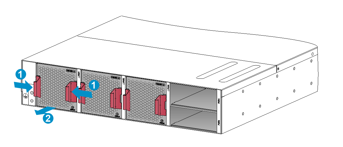
Figure7-4 Removing a power module (S12516X-AF switch)
|
(1) Press the latch to the handle direction |
|
(2) Pull the power module slowly out of the slot along the guide rails |
Replacing a card
Before you replace a card, remove all its cables. For an LPU, you can also remove the cable management brackets at the two sides of the LPU.
The replacement procedure is similar for MPUs, LPUs, and switching fabric modules. Before you rotate outward the ejector levers of the card, perform either of the following tasks:
· MPU or LPU—Loosen the captive screws on the card.
· Switching fabric module—Press the buttons on the ejector levers to release them.
If you are not to install a card in a slot, install a blank filler panel in the slot to ensure adequate ventilation and dust prevention.
Unless otherwise stated, the term "MPU" in this document refers to MPUs and cloud SEUs.
Replacing an MPU/LPU
1. Prepare an antistatic mat to place the removed MPU/LPU.
2. Wear an ESD wrist strap, and make sure it makes good skin contact and is reliably grounded. For more information, see "Installing FRUs."
3. (Optional.) For an LPU with foldable ejector levers, simultaneously pivot the ejector levers toward each other until they stop. See callout 1 in Figure7-8.
|
|
IMPORTANT: Before pivoting the ejector levers towards each other, remove the transceiver modules and cables that might interfere with this operation. |
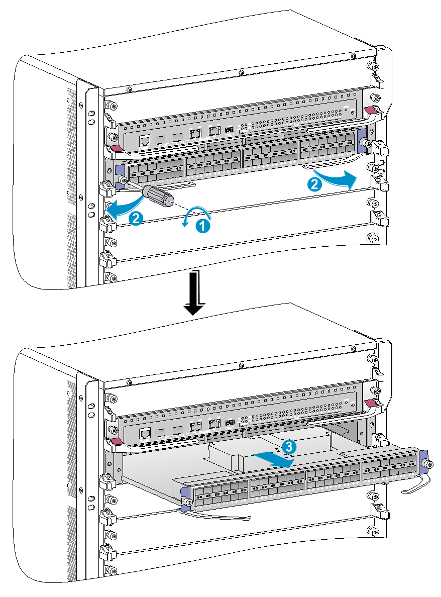
4. Use a Phillips screwdriver to loosen the captive screws on the MPU/LPU, as shown by callout 1 in Figure7-5, callout 1 in Figure7-6, or callout 2 in Figure7-8.
5. Perform either of the following tasks:
¡ For an LPU, S12516X-AF MPU, S12512X-AF MPU, and S12508X-AF MPU, hold the ejector levers on the card and rotate outward the ejector levers, as shown by callout 2 in Figure7-5 or callout 3 in Figure7-8. Then pull the card part way out of the slot.
¡ For an S12504X-AF MPU, pivot up the handle of the MPU and pull the MPU part way out of the slot, as shown by callout 2 in Figure7-6.
¡ For an S12502X-AF MPU, press the latch to release the ejector lever and fully open the ejector lever. See callout 1 in Figure7-7.
6. Supporting the MPU/LPU bottom with the left hand, slowly pull the MPU/LPU out of the slot along the guide rails with the right hand, as shown by callout 3 in Figure7-5, callout 3 in Figure7-6, or callout 4 in Figure7-8.
7. Place the removed MPU/LPU on the antistatic mat.
8. Install a new MPU/LPU. For the MPU/LPU installation procedure, see "Installing FRUs."
|
(1) Loosen the captive screw |
(2) Rotate the ejector levers outward |
|
(3) Pull the LPU slowly out of the slot along the guide rails |
|
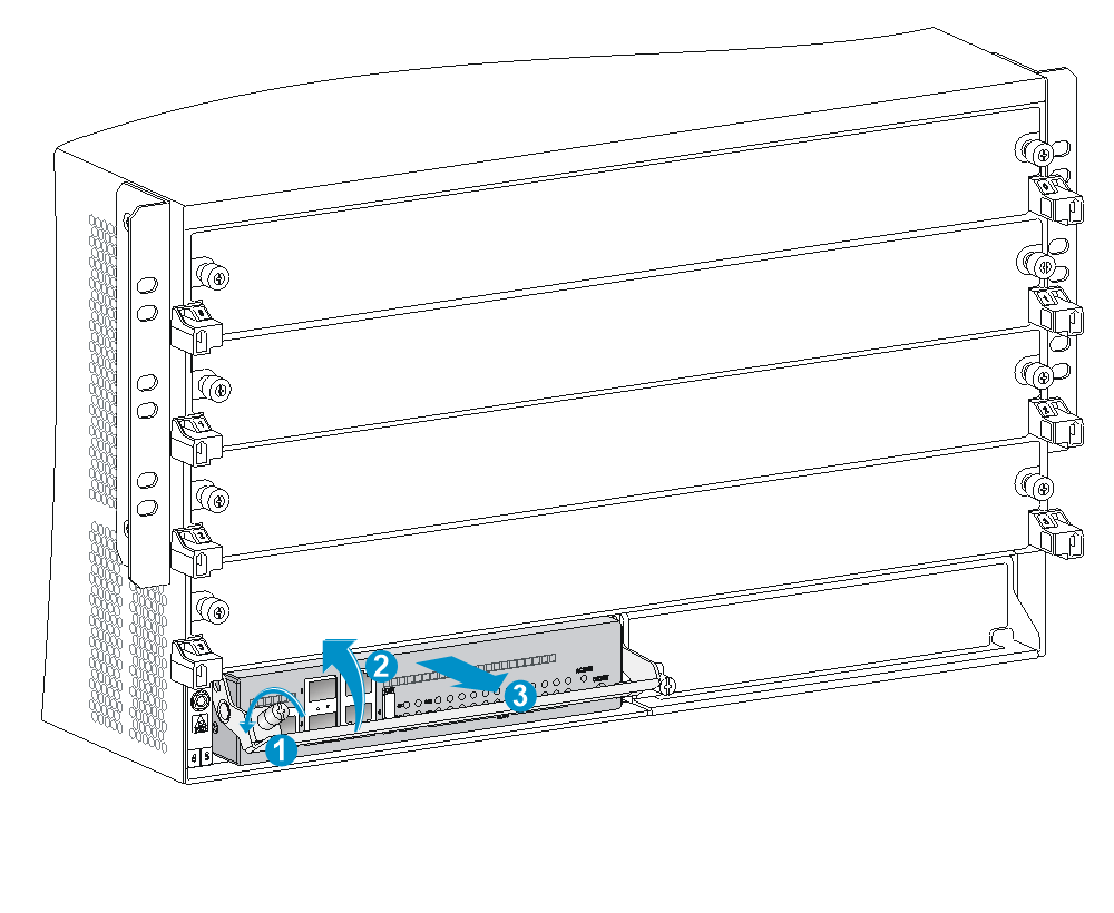
Figure7-6 Removing an S12504X-AF MPU
|
(1) Loosen the captive screw |
(2) Pivot up the handle of the MPU |
|
(3) Pull the MPU slowly out of the slot along the guide rails |
|
Figure7-7 Removing an S12504X-AF MPU
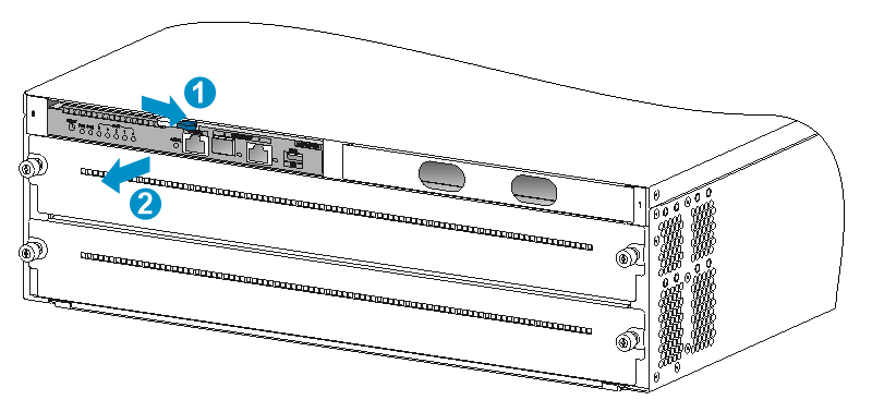
|
(1) Press the latch to release the ejector lever and fully open the ejector lever |
|
(2) Holding the ejector lever with one hand and the latch with the other, pull the MPU part out of the slot |
|
(3) Holding the MPU by the front panel with one hand and supporting the bottom with the other, pull the MPU out of the slot along the guide rails |
Figure7-8 Removing an LPU with foldable ejector levers (S12516X-AF)
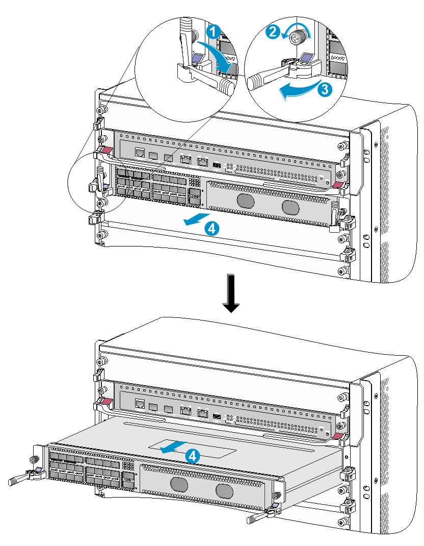
|
(1) Simultaneously pivot the ejector levers towards each other until they stop |
|
(2) Loosen the captive screws |
|
(3) Simultaneously privet the ejector levers away from each other until they stop |
|
(4) Holding the LPU by its front and supporting its bottom, pull the LPU out of the slot |
(Optional) Removing an interface module adapter
|
|
CAUTION: If you are not to install an LPU in an LPU slot that has an interface module adapter installed, remove the interface module adapter from the slot and install a filler panel in the slot. |
To remove an interface module adapter:
1. Loosen the screws that secure the interface module adapter to the switch.
2. Put your hand into the slot. Supporting the adapter top with your hand, pull out the adapter.
Figure7-9 Removing an interface module adapter
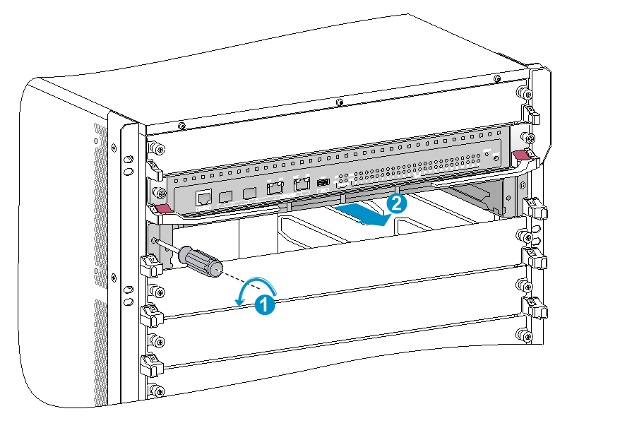
|
(1) Loosen the screws on the interface module adapter |
|
(2) Pull the interface module adapter slowly out of the LPU slot |
(Optional) Removing an LPU protective blank panel
A protective blank panel is installed over the LPU slots to avoid damage during transportation.
To remove the protective blank panel:
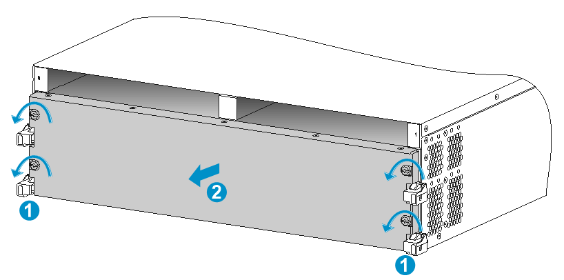
1. Remove the screws that secure the protective blank panel to the slots. See callout 1 in Figure7-10.
2. As shown by callout 2 in Figure7-10, remove the protective blank panel with both hands.
3. Keep the removed protective blank panel and screws secure for future use.
Figure7-10 Removing the protective blank panel
Replacing a switching fabric module
|
|
CAUTION: · Remove the fan tray before you remove a switching fabric module. Reinstall the fan tray immediately after you finish installing or replacing a switching fabric module on an operating switch. After the fan tray starts operating, you can replace or install switching fabric modules whose slots are covered by the other fan tray. · The smart speed adjustment feature increases the fan speed when only one fan tray is operating. Take noise protection measures such as wearing an earmuff or earplug. In addition, make good preparation before hot swapping a switching fabric module to minimize the operation time. |
To replace a switching fabric module:
1. Prepare an antistatic mat to place the removed switching fabric module.
2. Wear an ESD wrist strap, and make sure it makes good skin contact and is reliably grounded. For more information, see "Installing FRUs."
3. Press the buttons on the ejector levers to release the ejector levers. Simultaneously rotate outward the ejector levers and pull the switching fabric module part way out of the slot.
4. Holding the switching fabric module bottom with the right hand and the middle part with the left hand, pull the switching fabric module slowly out of the slot along the guide rails.
5. Place the removed switching fabric module on the antistatic mat.
6. Install a new switching fabric module. For the switching fabric module installation procedure, see "Installing FRUs."
Figure7-11 Replacing a switching fabric module (S12516X-AF switch)
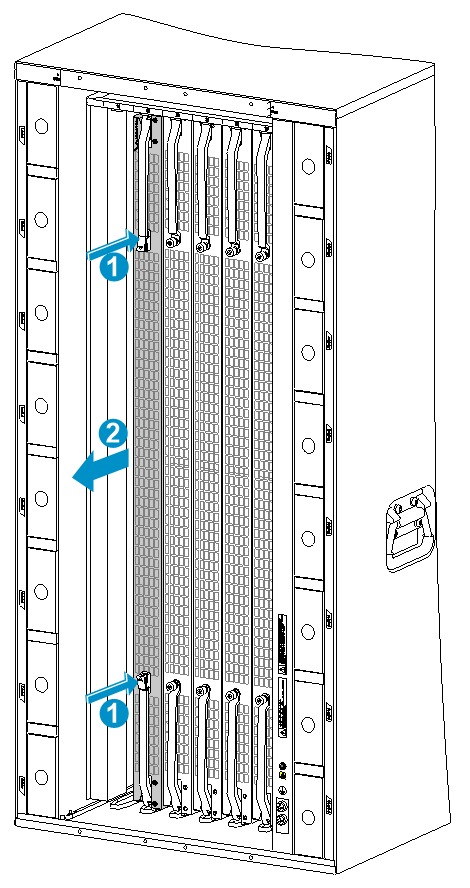
|
(1) Press the buttons on the ejector levers |
|
(2) Pull the switching fabric module slowly out of the slot along the guide rails |
Replacing a fan tray
|
|
WARNING! · To avoid bodily injury, do not touch the spinning fans when you replace the fan tray. · When you hot swap a fan tray, the fan rotation speed of the remaining fan trays automatically increases and the fan trays make louder noise. Take protection measures such as wearing an earmuff or earplug. In addition, make good preparations before the hot swapping to minimize the operation time. · Ensure electricity safety when you hot swap a fan tray. |
|
|
CAUTION: · To prevent dust from entering the device, keep the old fan tray installed in the chassis until a new fan tray is ready to be installed. · Before hot swapping a fan tray on an S12501X-AF switch, make sure the other two fan trays are operating correctly. Before hot swapping a fan tray on an S12500X-AF switch other than S12501X-AF, make sure the other fan tray is operating correctly. |
To replace a fan tray
1. Prepare an antistatic mat to place the fan tray to be removed.
2. Put on an ESD wrist strap, and make sure the wrist strap makes good skin contact and is reliably grounded. For more information, see "Installing FRUs."
3. (Optional.) Loosen the captive screws on the fan tray, as shown by callout 1 in Figure7-12.
Skip this step for an S12501X-AF fan tray.
4. Holding the handles on the fan tray, pull the fan tray part way out of the slot. After the fans stop rotating, support the fan tray bottom and pull it out from the chassis.
5. Place the removed fan tray on the antistatic mat.
6. Install a new fan tray. For more information, see "Installing FRUs."
Figure7-12 Removing a fan tray (S12516X-AF switch)
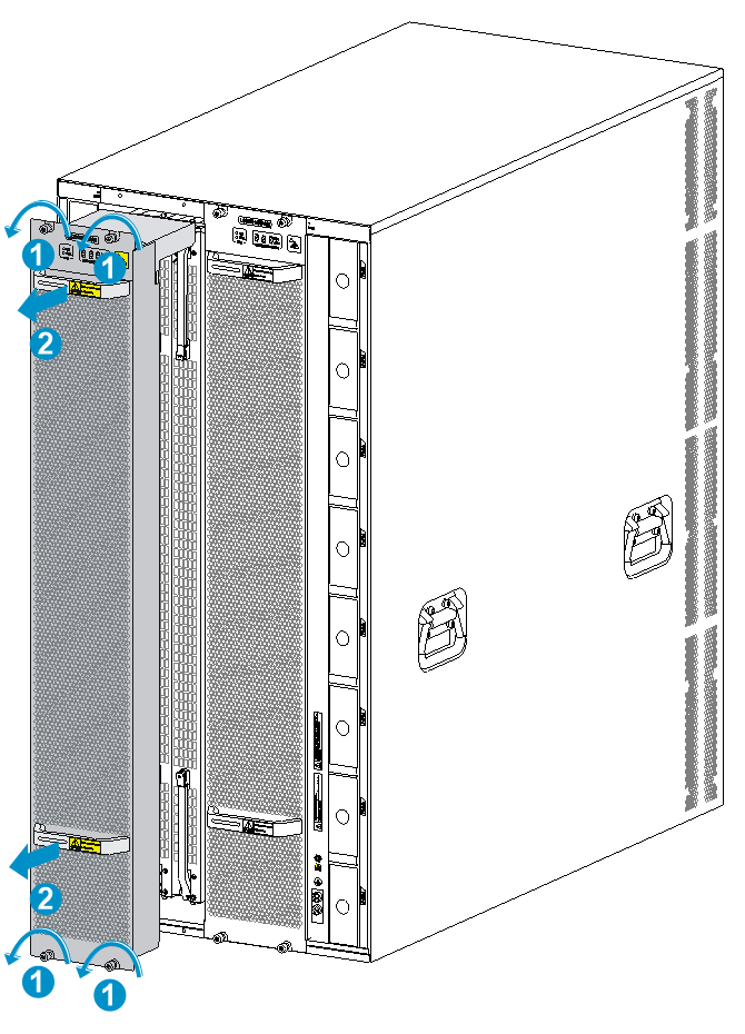
|
(2) Pull the fan tray slowly out of the chassis |
Figure7-13 Removing a fan tray (S12501X-AF switch)
|
(1) Hold the fan tray handles |
(2) Pull the fan tray gently out of the slot |
Replacing a transceiver module
|
|
WARNING! · When replacing a transceiver module on an operating switch, ensure electrical safety. · Do not stare at the fibers to avoid hurting your eyes. · Do not touch the golden plating on a transceiver module. · Make sure the transceiver modules at the two ends of an optical fiber are the same model. |
Replacing a CFP2 transceiver module
1. Wear an ESD wrist strap and make sure it makes good skin contact and is reliably grounded.
For more information, see "Installing FRUs."
2. Remove the optical fiber from the transceiver module.
3. Pull down the metal handle on the module to the horizontal position.
4. Hold the handle to pull the module horizontally and slowly out of the port.
5. Insert the dust plug into the module and put the module into its original packing materials.
6. Install a new CFP2 transceiver module in the port. For the installation procedure, see "Installing FRUs."
If you are not to install a new CFP2 transceiver module in the port, insert the dust plug that is provided with the LPU into the port, to prevent particles from entering the port.
Replacing an SFP+/SFP/QSFP+/QSFP28/QSFP-DD transceiver module
1. Wear an ESD wrist strap, and make sure it makes good skin contact and is reliably grounded.
For more information, see "Installing FRUs."
2. Remove the optical fibers from the transceiver module.
3. Pivot the clasp outward.
For a plastic pull latch, skip this step.
4. Grasp the clasp on the module and carefully pull the module out of the slot.
5. Insert the dust plugs into the removed module, and put the remove module into its original packaging materials.
6. Install a new SFP+/SFP/QSFP+/QSFP28/QSFP-DD transceiver module in the port. For the installation procedure, see "Installing FRUs."
If you are not to install a new SFP+/SFP/QSFP+/QSFP28/QSFP-DD transceiver module in the port, install the dust plug that is provided with the LPU into the port, to prevent particles from entering the port.
Replacing a CXP transceiver module
1. Wear an ESD wrist strap and make sure it makes good skin contact and is reliably grounded.
For more information, see "Installing FRUs."
2. Remove the optical fiber from the transceiver module.
3. With your forefinger, pull the module out of the slot carefully.
4. Insert the dust plug into the removed module, and put the removed module into its original shipping materials.
5. Install a new CXP transceiver module in the port. For the installation procedure, see "Installing FRUs."
If you are not to install a new CXP transceiver module in the port, insert the dust plug that is provided with the LPU into the port, to prevent particles from entering the port.
Replacing a CXP fiber cable
|
|
CAUTION: · If the cable cannot be removed or installed, verify that the removal or installation procedures are correct. · Pull the pull latch horizontally for smooth removal and avoiding damage. · If you are not to install a new CXP fiber cable in the port, insert the dust plug that is provided with the LPU into the port, to prevent particles from entering the port. |
To replace a CXP fiber cable:
1. Wear an ESD wrist strap, and make sure it makes good skin contact and is reliably grounded. For more information, see "Installing FRUs."
2. Use your forefinger to gently pull the cable connector out by its pull latch.
3. Put the removed cable into its original shipping materials.
4. Install a new CXP fiber cable in the port. For the installation procedure, see "Installing FRUs."
Replacing an SFP+/QSFP+/QSFP28/QSFP-DD/QSFP+ to SFP+ copper cable
|
|
CAUTION: · If the cable cannot be removed or installed, verify that the removal or installation procedures are correct. · Pull the pull latch horizontally for smooth removal and avoiding damage. · If you are not to install a new SFP+/QSFP+/QSFP28/QSFP-DD/QSFP+ to SFP+ copper cable in the port, insert the dust plug that is provided with the LPU into the port, to prevent particles from entering the port. |
|
|
IMPORTANT: The bend radius of the cable must be a minimum of eight times the cable diameter. |
To replace an SFP+/QSFP+/QSFP28/QSFP-DD/QSFP+ to SFP+ copper cable:
1. Wear an ESD wrist strap, and make sure it makes good skin contact and is reliably grounded. For more information, see "Installing FRUs."
2. Gently press the cable connector in, and then pull the pull latch on the cable outward to pull out the cable connector.
3. Install a new SFP+/QSFP+/QSFP28/QSFP-DD/QSFP+ to SFP+ copper cable in the port. For the installation procedure, see "Installing FRUs."
