- Table of Contents
-
- H3C S12500X-AF Switch Series Installation Guide-6W115
- 00-Preface
- 01-Chapter 1 Preparing for Installation
- 02-Chapter 2 Installing the Switch
- 03-Chapter 3 Installing FRUs
- 04-Chapter 4 Setting Up an IRF Fabric
- 05-Chapter 5 Connecting Your Switch to the Network
- 06-Chapter 6 Troubleshooting
- 07-Chapter 7 Replacement Procedures
- 08-Appendix A Engineering labels
- 09-Appendix B Cabling Recommendations
- 10-Appendix C Repackaging the Switch
- Related Documents
-
| Title | Size | Download |
|---|---|---|
| 04-Chapter 4 Setting Up an IRF Fabric | 713.76 KB |
Contents
Planning IRF fabric size and the installation site
Identifying the master switch and planning IRF member IDs
Planning IRF topology and connections
Identifying physical IRF ports on the member switches
Installing IRF member switches
Configuring basic IRF settings
Connecting the physical IRF ports
Verifying the IRF fabric configuration
4 Setting up an IRF fabric
You can use H3C IRF technology to connect and virtualize S12500X-AF switches into a large virtual switch called an "IRF fabric" for flattened network topology, high availability, scalability, and manageability. For more information about IRF, see H3C S12500-X&S12500X-AF Switch Series IRF Configuration Guide.
IRF fabric setup flowchart
The setup flow is shown in Figure4-1. For the actual procedure, see H3C S12500-X&S12500X-AF Switch Series IRF Configuration Guide for the software release you are using.
Figure4-1 IRF fabric setup flowchart
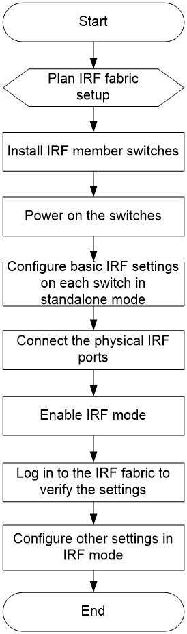
To set up an IRF fabric:
|
Step |
Description |
|
1. Plan IRF fabric setup. |
Plan the installation site and IRF fabric setup parameters: · Planning IRF fabric size and the installation site · Identifying the master switch and planning IRF member IDs |
|
2. Install IRF member switches. |
|
|
3. Power on the switches. |
N/A |
|
4. Configure basic IRF settings on each switch in standalone mode. |
See H3C S12500-X&S12500X-AF Switch Series IRF Configuration Guide. |
|
5. Connect the physical IRF ports. |
Connect physical IRF ports on switches. |
|
6. Enable IRF mode. |
See H3C S12500-X&S12500X-AF Switch Series IRF Configuration Guide. |
|
7. Verify the IRF settings. |
Log in to the IRF fabric at any member switch and verify that you can configure all member switches as if they were one node. |
|
8. Configure other settings in IRF mode. |
See H3C S12500-X&S12500X-AF Switch Series IRF Configuration Guide. |
Planning IRF fabric setup
This section describes issues that an IRF fabric setup plan must cover.
Planning IRF fabric size and the installation site
Plan IRF fabric size and the installation site, as follows:
1. Use H3C S12500-X&S12500X-AF Switch Series IRF Configuration Guide as a reference to identify the number of member switches that your system software version supports for an S12500X-AF IRF fabric.
2. Choose S12500X-AF switch models for your network.
An S12500X-AF IRF fabric supports a maximum of two member switches. The member switches must be the same model.
3. Select LPUs that can provide 10-GE/40-GE/100-GE ports.
The S12500X-AF switch series requires 10-GE/40-GE/100-GE ports for IRF connection. For more information about the LPUs, see H3C S12500X-AF Switch Series Hardware Reference.
4. Select SFP+/QSFP+/QSFP28/CXP/CFP2 transceiver modules and fibers for long distance transmission. Select SFP+/QSFP+/QSFP28/QSFP+ to SFP+ copper cables for short distance transmission. Select twisted pair cables to connect 10GBase-T ports over a short distance.
For more information about transceiver modules and cables, see H3C S12500X-AF Switch Series Hardware Reference.
5. Plan the installation site.
Identifying the master switch and planning IRF member IDs
Determine which switch you want to use as the master for managing all member switches in the IRF fabric.
An IRF fabric has only one master switch. You configure and manage all member switches in the IRF fabric at the CLI of the master. IRF member switches will automatically elect a master. You can affect the election result by assigning a high member priority to the intended master switch. For more information about master election, see H3C S12500-X&S12500X-AF Switch Series IRF Configuration Guide.
Prepare an IRF member ID assignment scheme. An IRF fabric uses member IDs to uniquely identify and manage its members, and you must assign each IRF member switch a unique member ID.
Planning IRF topology and connections
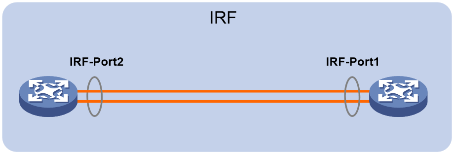
Connect the IRF member switches through IRF ports, the logical interfaces for the connections between IRF member switches. Each IRF member switch has two IRF ports: IRF-port 1 and IRF-port 2. To use an IRF port, you must bind a minimum of one physical port to it.
When connecting two neighboring IRF member switches, you must connect the physical ports of IRF-port 1 on one switch to the physical ports of IRF-port 2 on the other switch.
A two-member IRF fabric must use the daisy chain topology.
Figure4-2 Daisy chain topology
Identifying physical IRF ports on the member switches
Identify the physical IRF ports on the member switches according to your topology and connection scheme.
Only 10-GE/40-GE/100-GE ports on the switch can be used for IRF connection.
The switch supports multi-card link aggregation for IRF ports. You can bind up to eight physical ports to one IRF port.
Installing IRF member switches
|
Step |
Reference |
|
1. Prepare the installation site. |
|
|
2. Mount the IRF member switches to racks. |
See "Installing the switch." |
|
3. Install modules on IRF member switches. |
See "Installing FRUs." |
Configuring basic IRF settings
After you install the IRF member switches, power on the switches, and log in to each IRF member switch (see "Connecting your switch to the network") to configure their member IDs, member priorities, and IRF port bindings.
Follow these guidelines when you configure the switches:
· First configure the member IDs, member priorities, and IRF port bindings for the IRF member switches, save the configuration, connect the member switches, and change the operating mode of the switches to IRF mode.
· Assign the master switch higher member priority than any other switch.
· Bind physical ports to IRF-port 1 on one switch and to IRF-port 2 on the other switch.
· Execute the display irf configuration command to verify the basic IRF settings.
For more information about configuring basic IRF settings, see H3C S12500-X&S12500X-AF Switch Series IRF Configuration Guide.
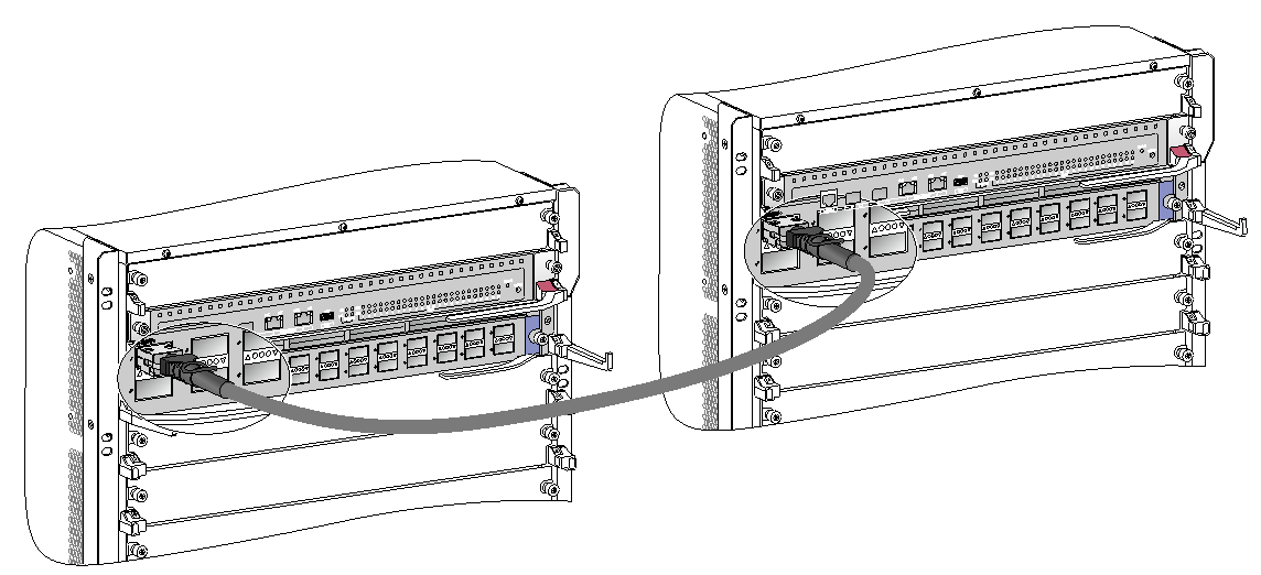
Connecting the physical IRF ports
Follow these guidelines to connect the 10GE/40GE/100GE ports between the IRF member switches:
· Use SFP+ transceiver modules and fibers or SFP+ copper cables to connect SFP+ ports. SFP+ copper cables are mainly used for short distance transmission.
· Use QSFP+ transceiver modules and fibers or QSFP+ copper cables to connect QSFP+ ports. QSFP+ copper cables are mainly used for short distance transmission.
· Use QSFP28 transceiver modules and fibers or QSFP28 copper cables to connect QSFP28 ports. QSFP+ copper cables are mainly used for short distance transmission.
· Use CXP transceiver modules and fibers to connect CXP ports.
· Use CFP2 transceiver modules and fibers to connect CFP2 ports.
· Use twisted pair cables to connect 10GBase-T ports.
· When connecting SFP+ ports, connect the transmit port of the SFP+ transceiver module at one end to the receive port of the SFP+ transceiver module at the other end.
· When connecting CFP2 ports, connect the transmit port of the CFP2 transceiver module at one end to the receive port of the CFP2 transceiver module at the other end.
· The transceiver modules at the two ends of an IRF link must be the same type.
For more information about installing transceiver modules, see "Installing FRUs." For more information about connecting fibers, see "Connecting your switch to the network."
Figure4-3 Connecting two IRF member switches
Verifying the IRF fabric configuration
After you finish configuring basic IRF settings and connecting IRF ports, verify the basic functionality of the IRF fabric, as follows:
1. Log in to the IRF fabric through the console port of any member switch.
2. Create a Layer 3 interface, assign it an IP address, and make sure the IRF fabric and the remote network management station can reach each other.
3. Use Telnet or SNMP to access the IRF fabric from the network management station. (See H3C S12500-X&S12500X-AF Switch Series Fundamentals Configuration Guide.)
4. Verify that you can manage all member switches as if they were one node.
5. Display the running status of the IRF fabric by using the commands in Table4-1.
Table4-1 Displaying and maintaining IRF configuration and running status
|
Task |
Command |
|
Display information about the IRF fabric |
display irf |
|
Display topology information about the IRF fabric |
display irf topology |
To avoid IP address collision and network problems, configure a minimum of one MAD mechanism to detect the presence of multiple identical IRF fabrics and handle collisions. For more information about MAD, see H3C S12500-X&S12500X-AF Switch Series IRF Configuration Guide.
