- Table of Contents
-
- H3C S12500X-AF Switch Series Installation Guide-6W115
- 00-Preface
- 01-Chapter 1 Preparing for Installation
- 02-Chapter 2 Installing the Switch
- 03-Chapter 3 Installing FRUs
- 04-Chapter 4 Setting Up an IRF Fabric
- 05-Chapter 5 Connecting Your Switch to the Network
- 06-Chapter 6 Troubleshooting
- 07-Chapter 7 Replacement Procedures
- 08-Appendix A Engineering labels
- 09-Appendix B Cabling Recommendations
- 10-Appendix C Repackaging the Switch
- Related Documents
-
| Title | Size | Download |
|---|---|---|
| 01-Chapter 1 Preparing for Installation | 1.37 MB |
1 Preparing for installation
H3C S12500X-AF Switch Series includes the following models:
· S12501X-AF
· S12502X-AF
· S12504X-AF
· S12508X-AF
· S12512X-AF
· S12516X-AF
Safety recommendations
To avoid possible bodily injury and equipment damage, read Compliance and Safety Manual provided with the switch and all safety recommendations in this chapter carefully before installation. The recommendations do not cover every possible hazardous condition.
General safety recommendations
· Keep the switch clean and dust-free.
· Do not place the switch on a moist area, and avoid liquid flowing into the switch.
· Make sure the ground is dry and flat and anti-slip measures are in place.
· Keep the switch and installation tools away from walk areas.
· Do not wear loose clothing, jewelry (for example, necklace) or any other things that could get caught in the switch when you install and maintain the switch.
Electricity safety
· Clear the work area of possible electricity hazards, such as ungrounded power extension cables, missing safety grounds, and wet floors.
· Locate the emergency power-off switch in the room before installation so you can quickly shut power off when an electrical accident occurs.
· Remove all external cables, including power cords, before moving the chassis.
· Do not work alone when the switch has power.
· Before performing a task that is hazardous when power is present, make sure the switch is completely powered off.
Handling safety
|
|
CAUTION: Do not hold the handle of a fan tray, a power module, or a card, or the air vents of the chassis to move the switch. Any attempt to move the switch with these parts might cause equipment damage and even bodily injury. |
Remove power modules, cards, and all external cables, including the power cords, before moving the chassis. As a best practice, use a mechanical lift, such as forklift truck, to move the chassis.
If no mechanical lift is used, follow these guidelines to move the chassis:
· Cooperate with a minimum of four people to move the chassis.
· Lift the chassis by using the chassis handles or by supporting the bottom from the two sides.
· Lift and put down the chassis slowly and never move suddenly.
ESD prevention
To prevent the electric component from being damaged by electrostatic discharge (ESD), follow these guidelines:
· Ground the switch reliably. For how to ground your switch, see "Installing the switch."
· Always wear an ESD wrist strap and make sure it is reliably grounded when installing FRUs. For how to use an ESD wrist strap, see "Installing FRUs."
· Hold a PCB by its edges. Do not touch any electronic components or printed circuit.
· Put cards away in antistatic bags for future use.
Laser safety
|
|
WARNING! Do not stare into any fiber port or view directly with non-attenuating optical instruments when the switch has power. The laser light emitted from the fiber port might hurt your eyes. |
The switch is a Class 1 laser product.
Examining the installation site
The switch must be used indoors. To ensure correct operation and long lifespan of your switch, the installation site must meet the requirements in this section.
Weight support
Make sure the floor can support the total weight of the rack, chassis, cards, power modules, and all other components. To mount the switch in a rack, make sure the slide rails can support the total weight of the switch and its accessories (cards, power modules, and transceiver modules).
Additionally, the floor and slide rail loading plan must also consider system expansion, such as adding more cards. For more information, see H3C S12500X-AF Switch Series Hardware Reference.
Temperature
|
CAUTION: If condensation appears on the chassis when you move it to a high-temperature environment, dry the chassis before powering it on to avoid short circuits. |
To ensure correct operation of the switch, make sure the room temperature meets the requirements in Table1-1.
Table1-1 Temperature requirements
|
Temperature |
Range |
|
Operating temperature |
0°C to 40°C (32°F to 104°F) |
|
Storage temperature |
–40°C to +70°C (–40°F to +158°F) |
Humidity
Maintain appropriate humidity in your equipment room, as described in Table1-2.
· Lasting high relative humidity can cause poor insulation, electricity leakage, mechanical property change of materials, and metal corrosion.
· Lasting low relative humidity can cause washer contraction and ESD and cause problems including loose mounting screws and circuit failure.
Table1-2 Humidity requirements
|
Humidity |
Range |
|
Operating humidity |
5% to 95%, noncondensing |
|
Storage humidity |
5% to 95%, noncondensing |
Cleanliness
Dust buildup on the chassis might result in electrostatic adsorption, which causes poor contact of metal components and contact points. In the worst case, electrostatic adsorption can cause communication failure.
Table1-3 Dust concentration limit in the equipment room
|
Substance |
Concentration limit (particles/m3) |
|
Dust particles |
≤ 3 x 10⁴ (No visible dust on desk in three days) |
|
NOTE: Dust particle diameter ≥ 5 µm |
|
The equipment room must also meet limits on salts, acids, and sulfides to eliminate corrosion and premature aging of components, as shown in Table1-4.
Table1-4 Harmful gas limits in the equipment room
|
Gas |
Max. (mg/m3) |
|
SO2 |
0.2 |
|
H2S |
0.006 |
|
NH3 |
0.05 |
|
Cl2 |
0.01 |
EMI
All electromagnetic interference (EMI) sources, from outside or inside of the switch and application system, adversely affect the switch in the following ways:
· A conduction pattern of capacitance coupling.
· Inductance coupling.
· Electromagnetic wave radiation.
· Common impedance (including the grounding system) coupling.
To prevent EMI, perform the following tasks:
· If AC power is used, use a single-phase three-wire power receptacle with protection earth (PE) to filter interference from the power grid.
· Keep the switch far away from radio transmitting stations, radar stations, and high-frequency devices.
· Use electromagnetic shielding, for example, shielded interface cables, when necessary.
Grounding
Using a good grounding system to protect your switch against lightning shocks, interferences, and ESD is essential to the operating reliability of your switch.
Make sure the equipment room grounding system has a resistance value less than 1 ohm.
For more information about grounding the switch, see "Installing the switch."
Power
Perform the following tasks to meet the power requirements:
1. Calculate the system power consumption.
The system power consumption varies by card type and density. For more information about system power consumption calculation, see H3C S12500X-AF Switch Series Hardware Reference.
2. Identify the number of power modules.
The total maximum output power of all power modules must be higher than the system power consumption. For more information about available power modules, see H3C S12500X-AF Switch Series Hardware Reference.
3. Verify that the power system at the installation site meets the requirements of the power modules, including the input method and rated input voltage. For more information about power module specifications, see H3C S12500X-AF Switch Series Hardware Reference.
Cooling
Plan the installation site for adequate ventilation:
· Leave a minimum of 30 cm (11.81 in) of clearance at the inlet and outlet air vents.
· The rack for the switch has a good cooling system.
· The installation site has a good cooling system.
· Verify that the airflow design of the chassis meets the airflow design of the installation site.
Figure1-1 Airflow through the switch (S12516X-AF switch)
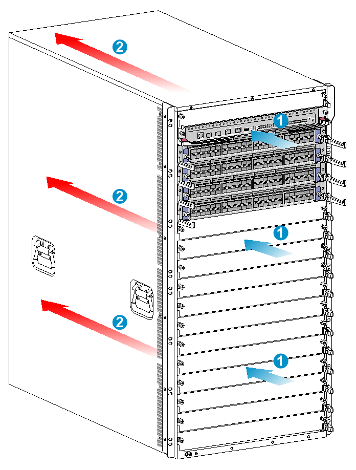
|
(1) Chassis air intake direction |
(2) Chassis air exhaust direction |
Space
For easy installation and maintenance, follow these space requirements:
· Reserve a minimum of 1.2 m (3.94 ft) of clearance between the rack and walls or other devices.
· Make sure the rack has enough space to accommodate the switch.
For more information about chassis dimensions, see "Device dimensions and rack requirements."
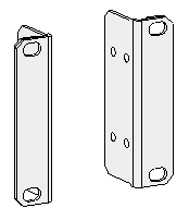
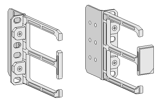
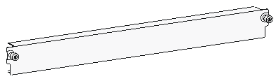
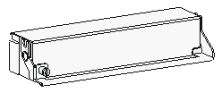
Installation accessories
Make sure you have all the required installation accessories ready for the installation.
Table1-5 Installation accessories
|
Product code |
Description |
Quantity |
Applicable device models |
|
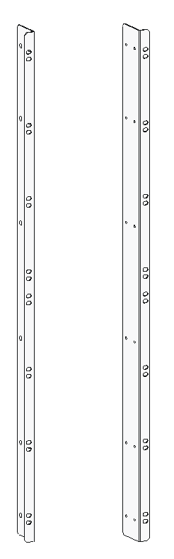
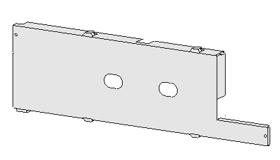
2150A08S |
S12516X-AF mounting brackets
|
1 pair |
S12516X-AF |
|
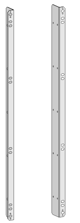
2150A0CL |
S12512X-AF mounting brackets
|
1 pair |
S12512X-AF |
|
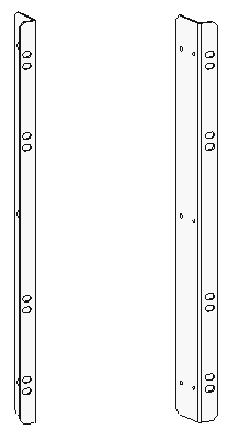
2150A0AX |
S12508X-AF mounting brackets
|
1 pair |
S12508X-AF |
|
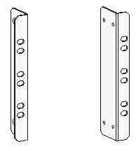
2150A0BW |
S12504X-AF mounting brackets
|
1 pair |
S12504X-AF |
|
2150A0D6 |
S12502X-AF mounting brackets
|
1 pair |
S12502X-AF |
|
2150A0EH |
S12501X-AF mounting brackets
|
1 pair |
S12501X-AF |
|
2150A05N |
S12501X-AF rack mount rail kit
|
1 pair of slide rails and 1 pair of chassis rails |
S12501X-AF |
|
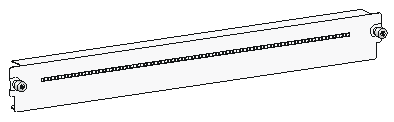
2113A0YW |
S12500X-AF MPU filler panel
|
2 |
S12516X-AF S12512X-AF S12508X-AF |
|
2113A1EH |
S12504X-AF MPU filler panel
|
2 |
S12504X-AF |
|
2113A1P2 |
S12502X-AF MPU filler panel |
2 |
S12502X-AF |
|
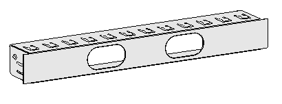
2113A0YV |
S12500X-AF LPU filler panel
|
· S12516X-AF: 16 · S12512X-AF: 12 · S12508X-AF: 8 · S12504X-AF: 4 |
All S12500X-AF switch models |
|
2124A01H |
S12502X-AF LPU filler panel
|
1 |
S12502X-AF |
|
2114A0AV |
S12501X-AF LPU filler panel
|
1 |
S12501X-AF |
|
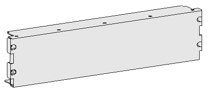
2114A0A4 |
S12502X-AF power module filler panel
|
4 |
S12502X-AF |
|
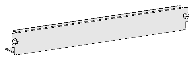
2114A09Q |
S12500X-AF power module filler panel
|
· S12516X-AF: 16 · S12512X-AF: 12 · S12508X-AF: 8 · S12504X-AF: 4 · S12501X-AF: 1 |
S12516X-AF S12512X-AF S12508X-AF S12504X-AF S12501X-AF |
|
2114A0A3 |
S12502X-AF fan tray filler panel
|
1 |
S12502X-AF |
|
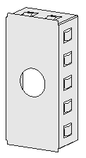
2150A0AB |
S12500X-AF cable management bracket
|
· S12516X-AF: 32 · S12512X-AF: 24 · S12508X-AF: 16 · S12504X-AF: 8 · S12502X-AF: 4 |
S12516X-AF S12512X-AF S12508X-AF S12504X-AF S12502X-AF |
|
26020141 26020075 |
M6 screw and cage nut
|
· S12516X-AF: 30 pairs · S12512X-AF: 14 pairs · S12508X-AF: 14 pairs · S12504X-AF: 12 pairs · S12502X-AF: 4 pairs · S12501X-AF: 10 pairs |
All S12500X-AF switch models |
|
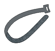
2110A042 |
Releasable cable tie
|
1 |
All S12500X-AF switch models |
|
2110A05W |
Hook-and-loop cable tie
|
1 |
All S12500X-AF switch models |
|
0404A0EE |
Grounding cable
|
1 |
All S12500X-AF switch models |
|
28050001 |
ESD wrist strap
|
1 |
All S12500X-AF switch models |
|
04042967 |
Console cable
|
1 |
All S12500X-AF switch models |
|
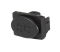
14990101 |
SFP port dust plug
|
Same number as the SFP/SFP+ ports |
S12500X-AF LPUs with SFP/SFP+ ports |
|
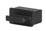
1499A00C |
QSFP port dust plug
|
Same number as the QSFP ports |
S12500X-AF LPUs with QSFP ports |
|
1499A00S |
CFP2 port dust plug
|
Same number as the CFP2 ports |
S12500X-AF LPUs with CFP2 ports |