- Table of Contents
-
- H3C S12500X-AF Switch Series Installation Guide-6W115
- 00-Preface
- 01-Chapter 1 Preparing for Installation
- 02-Chapter 2 Installing the Switch
- 03-Chapter 3 Installing FRUs
- 04-Chapter 4 Setting Up an IRF Fabric
- 05-Chapter 5 Connecting Your Switch to the Network
- 06-Chapter 6 Troubleshooting
- 07-Chapter 7 Replacement Procedures
- 08-Appendix A Engineering labels
- 09-Appendix B Cabling Recommendations
- 10-Appendix C Repackaging the Switch
- Related Documents
-
| Title | Size | Download |
|---|---|---|
| 02-Chapter 2 Installing the Switch | 13.13 MB |
Confirming installation preparations
Installing the switch in a rack
Switch dimensions and rack requirements
Attaching mounting brackets and chassis rails to the switch
Attaching slide rails to the rack
Installing cage nuts for attaching mounting brackets
2 Installing the switch
|
|
IMPORTANT: Keep the packages of the switch and the components for future use. |
Confirming installation preparations
Before you install the switch, verify that:
· You have read "Preparing for installation" carefully and the installation site meets all the requirements.
· A 19-inch rack is ready for use and the rack has enough space to accommodate the switch.
For information about how to install a rack, see the rack installation guide.
· The rack is sturdy and reliably grounded.
· No debris exists inside or around the rack.
· The heaviest device is placed at the bottom of the rack.
· The rack can provide power as required by the device. For information about the system power consumption and power module specifications, see H3C S12500X-AF Switch Series Hardware Reference.
· The total height of the switches to be installed is not higher than the available installation height of the rack and enough clearance is reserved for cable routing.
· The switch is ready for installation and has been carried to a place near the rack and convenient for moving.
Installing the switch in a rack
Switch dimensions and rack requirements
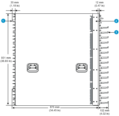
Figure2-1 S12516X-AF switch dimensions
|
(1) Fan tray handle |
(2) Mounting bracket |
|
(3) Cable management bracket |
|
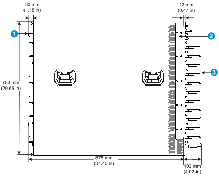
Figure2-2 S12512X-AF switch dimensions
|
(1) Fan tray handle |
(2) Mounting bracket |
|
(3) Cable management bracket |
|
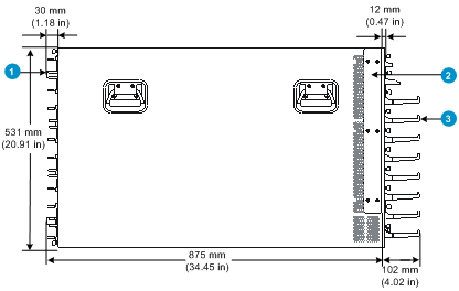
Figure2-3 S12508X-AF switch dimensions
|
(1) Fan tray handle |
(2) Mounting bracket |
|
(3) Cable management bracket |
|
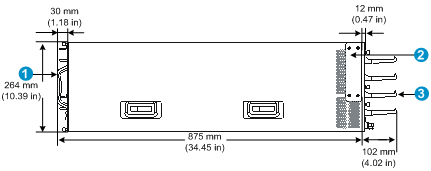
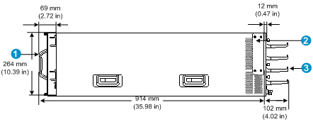
Figure2-4 S12504X-AF switch dimensions (with the LSXM104XFAN fan trays)
|
(1) Fan tray handle |
(2) Mounting bracket |
|
(3) Cable management bracket |
|
Figure2-5 S12504X-AF switch dimensions (with the LSXM104XFANH fan trays)
|
(1) Fan tray handle |
(2) Mounting bracket |
|
(3) Cable management bracket |
|
Figure2-6 S12502X-AF switch dimensions
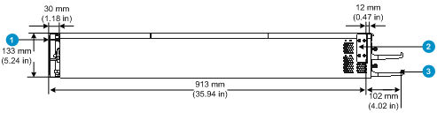
|
(1) Fan tray handle |
(2) Mounting bracket |
|
(3) Cable management bracket |
|
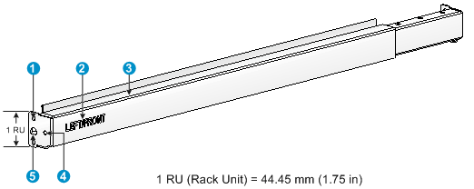
Figure2-7 S12501X-AF switch dimensions
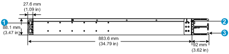
|
(1) Power module latch |
(2) Mounting bracket |
|
(3) Cable management bracket |
|
To mount the switch in an enclosed rack, make sure the rack meets the requirements described in Table2-1.
Table2-1 Switch dimensions and rack requirements
|
Chassis dimensions |
Rack requirements |
|
S12516X-AF |
· A minimum of 1.1 m (3.61 ft) in depth (recommended) · A minimum of 130 mm (5.12 in) between the front rack post and the front door. · A minimum of 950 mm (37.40 in) between the front rack post and the rear door. |
|
· Height—931 mm (36.65 in)/21 RU · Width—440 mm (17.32 in) · Depth (chassis only)—857 mm (33.74 in) · Depth (fully configured)—977 mm (38.46 in) ¡ 102 mm (4.02 in) from the rear-facing surface of the mounting bracket to the front end of the cable management bracket ¡ 875 mm (34.45 in) from the rear-facing surface of the mounting bracket to the fan tray handle |
|
|
S12512X-AF |
|
|
· Height—753 mm (29.65 in)/17 RU · Width—440 mm (17.32 in) · Depth (chassis only)—857 mm (33.74 in) · Depth (fully configured)—977 mm (38.46 in) ¡ 102 mm (4.02 in) from the rear-facing surface of the mounting bracket to the front end of the cable management bracket ¡ 875 mm (34.45 in) from the rear-facing surface of the mounting bracket to the fan tray handle |
|
|
S12508X-AF |
|
|
· Height—531 mm (20.91 in)/12 RU · Width—440 mm (17.32 in) · Depth (chassis only)—857 mm (33.74 in) · Depth (fully configured)—977 mm (38.46 in) ¡ 102 mm (4.02 in) from the rear-facing surface of the mounting bracket to the front end of the cable management bracket ¡ 875 mm (34.45 in) from the rear-facing surface of the mounting bracket to the fan tray handle |
|
|
S12504X-AF |
|
|
· Height—264 mm (10.39 in)/6 RU · Width—440 mm (17.32 in) · Depth (chassis only)—857 mm (33.74 in) · Depth (fully configured) with the LSXM104XFAN fan trays installed—977 mm (38.46 in) ¡ 102 mm (4.02 in) from the rear-facing surface of the mounting bracket to the front end of the cable management bracket ¡ 875 mm (34.45 in) from the rear-facing surface of the mounting bracket to the fan tray handle · Depth (fully configured) with the LSXM104XFAN fan trays installed—1016 mm (40 in) ¡ 102 mm (4.02 in) from the rear-facing surface of the mounting bracket to the front end of the cable management bracket ¡ 914 mm (35.98 in) from the rear-facing surface of the mounting bracket to the fan tray handle |
|
|
S12502X-AF |
|
|
· Height—133 mm (5.24 in)/3 RU · Width—440 mm (17.32 in) · Depth (chassis only)—895 mm (35.24 in) · Depth (fully configured)—1015 mm (39.96 in) ¡ 102 mm (4.02 in) from the rear-facing surface of the mounting bracket to the front end of the cable management bracket ¡ 913 mm (35.94 in) from the rear-facing surface of the mounting bracket to the fan tray handle |
|
|
S12501X-AF |
|
|
· Height—88.1 mm (3.47 in) (2 RU). · Width—440 mm (17.32 in). · Depth (chassis only)—856 mm (33.70 in) · Depth (fully configured)—975.6 mm (38.41 in) ¡ 92 mm (3.62 in) from the rear-facing surface of the mounting bracket to the front end of the cable management bracket ¡ 883.6 mm (34.79 in) from the rear-facing surface of the mounting bracket to the power module latch |
|
|
NOTE: As a best practice, use a rack that has a single door at the front. |
Attaching mounting brackets and chassis rails to the switch
|
|
IMPORTANT: As a best practice, fasten M4 screws to a torque of 12 kgf-cm (1.18 Nm). |
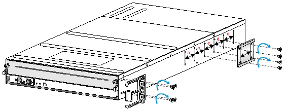
This installation procedure is applicable only to the S12501X-AF switch. The other S12500X-AF switch models are shipped with mounting brackets installed.
Attach the mounting brackets to the sides of the chassis near the front panel. The cable management brackets have been attached to the mounting brackets and do not require separate installation.
Attach the chassis rails to installation position a, b, c, d, or e as shown in Figure2-8. The installation position depends on the distance between the front and the rear rack posts (rack depth).
To attach the mounting brackets and chassis rails to the switch:
1. Read the sign on each mounting bracket to identify the left and right mounting brackets. The left mounting bracket is marked L and the right mounting bracket is marked R.
2. Align the mounting holes in the wide flange of the mounting brackets with the screw holes in the chassis. See Figure2-8.
3. Use M4 screws provided with the switch to attach the mounting brackets to the chassis.
4. Determine the installation position of the chassis rails based on the rack depth.
Table2-2 Rack depth and chassis rail installation position
|
Rack depth |
Chassis rail installation position |
|
552 to 799 mm (21.73 to 31.46 in) |
Positon a |
|
617 to 864 mm (24.29 to 34.02 in) |
Positon b |
|
682 to 929 mm (26.85 to 36.57 in) |
Positon c |
|
747 to 994 mm (29.41 to 39.13 in) |
Positon d |
|
812 to 1059 mm (31.97 to 41.69 in) |
Positon e |
5. Align the mounting holes in the chassis rails with the screw holes in the chassis. See Figure2-8.
6. Use M4 screws provided with the switch to secure the chassis rails to the chassis.
Figure2-8 Installing a mounting bracket and chassis rail
Attaching slide rails to the rack
|
|
IMPORTANT: · The switch is heavy. Install the slide rails at the lowest possible position. · As a best practice, fasten M4 screws to a torque of 12 kgf-cm (1.18 Nm) and M6 screws to a torque of 30 kgf-cm (2.94 Nm). |
Skip this section if slide rails have been installed on the rack.
Before you attach slide rails to the rack, verify that the slide rails can support the total weight of the switch and its accessories. Table2-3 lists the switch weight and applicable slide rails.
Table2-3 Switch weight and applicable slide rails
|
Switch model |
Chassis weight (full configuration) |
Applicable slide rails |
||
|
Model |
Adjustment range |
Occupied space |
||
|
S12516X-AF |
400 kg (881.83 lb) |
LSXM1BSR |
630 to 900 mm (24.80 to 35.43 in) |
1 RU |
|
S12512X-AF |
300 kg (661.36 lb) |
LSXM1BSR |
630 to 900 mm (24.80 to 35.43 in) |
1 RU |
|
LSTM2KSGD0 |
500 to 800 mm (19.69 to 31.50 in) |
2 RU |
||
|
S12508X-AF |
220 kg (485.01 lb) |
LSXM1BSR |
630 to 900 mm (24.80 to 35.43 in) |
1 RU |
|
LSTM2KSGD0 |
500 to 800 mm (19.69 to 31.50 in) |
2 RU |
||
|
S12504X-AF |
120 kg (264.55 lb) |
LSVM1BSR10 |
630 to 850 mm (24.80 to 33.46 in) |
N/A |
|
S12502X-AF |
70 kg (154.32 lb) |
LSVM1BSR10 |
630 to 850 mm (24.80 to 33.46 in) |
N/A |
|
S12501X-AF |
37 kg (81.57 lb) |
S12501X-AF slide rails (provided) |
552 to 1059 mm (21.73 to 41.69 in) |
N/A |
|
|
NOTE: The guide rail of the LSVM1BSR10 side rail is at the bottom of the slide rail. After a chassis is placed on the LSVM1BSR10 side rail, the slide rail bottom aligns with the chassis bottom. |
Attaching the LSXM1BSR slide rails (for the S12516X-AF, S12512X-AF, and S12508X-AF switches)
1. Read the signs on the slide rails to identify the right and left slide rails and their front and rear ends.
Figure2-9 Left slide rail
|
(1) Slide rail installation hole |
(2) Sign |
|
(3) Guide rail |
(4) Front plate installation hole |
|
(5) Locating tongue |
|
Table2-4 Description for signs on the slide rails
|
Sign |
Meaning |
Remarks |
|
LEFT/FRONT |
Front end of the left slide rail |
Mount this end to the front left rack post. |
|
RIGHT/FRONT |
Front end of the right slide rail |
Mount this end to the front right rack post. |
|
|
NOTE: · The LSXM1BSR slide rail accessories include the left slide rail, right slide rail, and front plate. · One rack unit (RU) has two standard installation holes and one auxiliary installation hole in the middle. The space between a standard installation hole and an auxiliary installation hole is wider than the space between two adjacent standard installation holes. |
2. Mark the slide rail installation positions on the rack posts.
¡ Align the locating tongues of the slide rails with the target auxiliary holes in the rack posts, as shown by callout 1 in Figure2-11.
¡ Mark the start installation hole at the same height on each rack post.
3. Install cage nuts in the marked standard hole and the standard hole within the same RU. A total of eight cage nuts are required, with two cage nuts for each rack post.
4. Align the installation holes on the front end of the slide rail with the cage nuts on a front rack post.
5. Keep the slide rail horizontal and adjust its length until the locating tongues on the slide rail are attached to the auxiliary holes on the rack posts.
6. Use M6 screws to secure the slide rail to the front and back rack posts, as shown by callout 2 in Figure2-11.
To ensure load bearing, each installation hole of the slide rail requires a screw. A total of four M6 screws are required to secure the slide rail to the rack.
7. Repeat steps 4, 5, and 6 to install the other slide rail.
8. Attach the front plate to the rack:
a. Orient the front plate so that the front of the plate faces outward. Figure2-10 shows the rear of the plate.
Figure2-10 Rear of a front plate
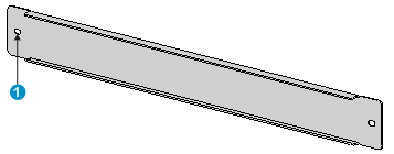
|
(1) Installation hole |
b. Align the installation holes in the front plate with the front plate installation holes in the slide rails, and fasten the screws, as shown by callout 3 in Figure2-11.
Two M4 screws are required to secure the front plate to the rack.
Figure2-11 Installing the LSXM1BSR slide rails
Attaching the LSTM2KSGD0 slide rails (for the S12512X-AF and S12508X-AF switches)
1. Read the signs on the slide rails to identify the right and left slide rails and their front and rear ends.
Figure2-12 Right slide rail
|
(1) Guide rail |
(2) Sign |
(3) Installation hole |
Table2-5 Description for signs on the slide rails
|
Sign |
Meaning |
Remarks |
|
F/L |
Front end of the left slide rail |
Mount this end to the front left rack post. |
|
F/R |
Front end of the right slide rail |
Mount this end to the front right rack post. |
2. Mark the slide rail installation positions on the rack posts.
¡ Make sure the top flange of the slide rail aligns with the middle of the narrower metal area between holes on the right front rack post, as shown by callout 1 in Figure2-13.
¡ Make sure the slide rail installation positions are at the same height on the four rack posts so that the switch can be placed on the slide rails evenly.
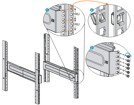
3. Install cage nuts in the marked square holes within 2 RU at the same height on the rack posts, as shown by callout 2 in Figure2-13. Each rack post requires six cage nuts.
a. Insert the lower ear of a cage nut into the corresponding installation hole.
b. Compress the upper and lower ears of the cage nut to lead the upper ear through the hole.
4. Align the installation holes on the front end of the slide rail with the cage nuts on a front rack post, and use six M6 screws to attach the slide rail to the rack post, as shown by callout 3 in Figure2-13.
5. Keep the slide rail horizontal and adjust its length until the installation holes on the rear end of the slide rail touch the cage nuts on the rear rack post. Then use screws to attach the slide rail to the rear rack post.
Install a screw in each mounting hole of the slide rail to ensure its weight bearing capacity.
6. Repeat steps 4 and 5 to install the other slide rail.
Figure2-13 Installing the LSTM2KSGD0 slide rails
Attaching the LSVM1BSR10 slide rails (for the S12504X-AF switch)
1. Read the signs on the slide rails to identify the right and left slide rails and their front and rear ends.
Figure2-14 Right slide rail
|
(1) Sign |
(2) Guide rail |
|
(3) Ventilation holes |
(4) Installation hole |
2. Mark the slide rail installation position on the rack posts.
¡ Make sure the positioning tab at the bottom of the slide rail is inserted into the lowest square hole within the 2 RU space on a rack post. The installation holes on the slide rail are aligned with the square holes in the rack post. See callouts 1 and 2 in Figure2-15.
¡ Make sure the slide rail installation positions are at the same height on the four rack posts so that the switch can be placed on the slide rails evenly.
3. Install cage nuts in the marked square holes within 2 RU at the same height on the rack posts, as shown by callout 3 in Figure2-15. Each rack post requires four cage nuts.
a. Insert the lower ear of a cage nut into the corresponding installation hole.
b. Compress the upper and lower ears of the cage nut to lead the upper ear through the hole.
4. Perform the following tasks as shown by callout 4 in Figure2-15:
a. Align the installation holes on the two ends of a slide rail with the cage nuts on the front and rear rack posts.
b. Compress the slide rail, making sure the positioning tabs at both ends of the slide rail are inserted into the lowest square holes within the 2 RU space on the rack posts.
c. Use M6 screws to secure the slide rail to the rack posts.
|
|
TIP: Install a screw in each mounting hole of the slide rail to ensure its weight bearing capacity. |
5. Repeat step 4 to install the other slide rail.
Figure2-15 Installing the LSVM1BSR10 slide rails
Attaching the LSVM1BSR10 slide rails (for the S12502X-AF switch)
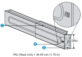
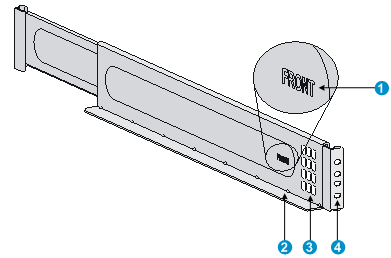
1. Read the signs on the slide rails to identify the front and rear ends of the slide rails.
When installing a slide rail, make sure the "FRONT" mark is near the front rack post.
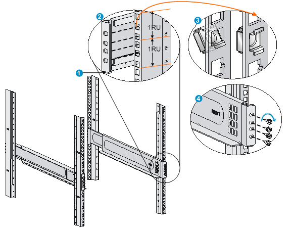
2. Insert the positioning tab at each side of a slide rail into the lowest square hole within the 2 RU installation space on the front and rear rack posts. Align the installation holes on the slide rail with the square holes in the rack post. See callouts 1 and 2 in Figure2-16.
3. Mark the lowest three slide rail installation holes on each front rack post and all four slide rail installation holes on each rear rack post.
Make sure the slide rail installation positions are at the same height on the four rack posts so that the switch can be placed on the slide rails evenly.
4. Install cage nuts in the marked square holes, as shown by callout 3 in Figure2-16.
5. Use screws to secure the slide rails to the rack posts as shown by callout 4 in Figure2-16.
¡ On each front rack post, install screws only in the lowest two marked installation holes. The second uppermost marked installation hole is reserved for the mounting bracket.
¡ On each rear rack post, install M6 screws in all four marked installation holes.
Figure2-16 Installing the LSVM1BSR10 slide rails
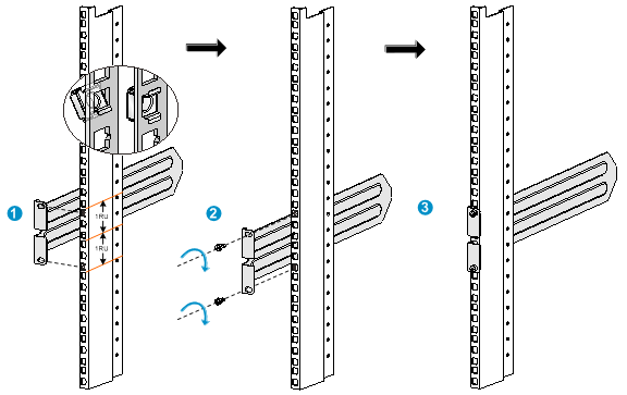
Attaching the slide rails (for the S12501X-AF switch)
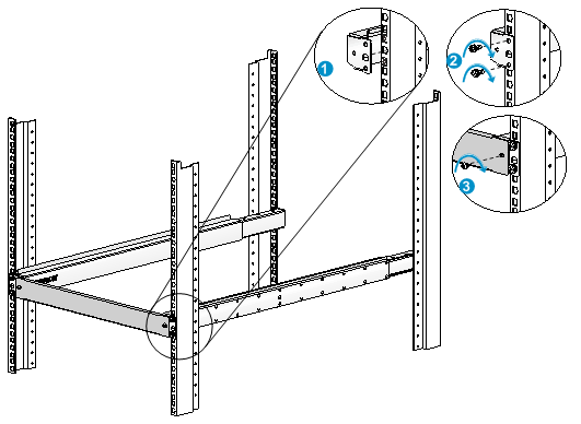
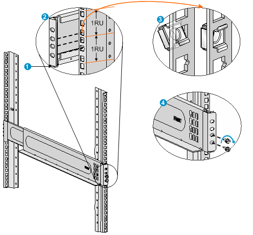
1. Determine the slide rail installation position on the rack and mark the slide rail installation holes on a rear rack post. As shown in Figure2-17, the slide rail is 2 RU high.
2. Install a cage nut in each marked installation hole, as shown by callout 1 in Figure2-17.
3. Align the installation holes in the slide rail with the cage nuts on the rack post, and use M6 screws to secure the slide rail to the rack post. See callout 2 in Figure2-17.
4. Repeat the proceeding steps to install the other slide rail.
Make sure the two slide rails are at the same height.
Figure2-17 Installing the S12501X-AF slide rails
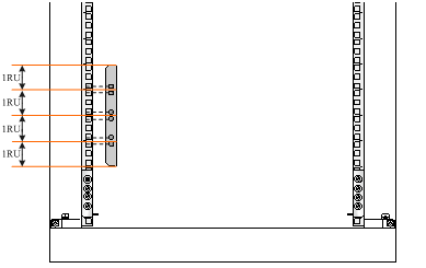
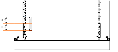
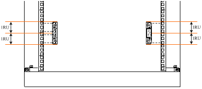
Installing cage nuts for attaching mounting brackets
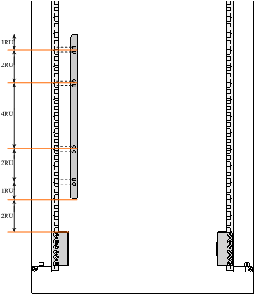
1. As shown in Figure2-18, Figure2-19, Figure2-20, Figure2-21, Figure2-22, and Figure2-23, mark the cage nut installation holes for the S12516X-AF, S12512X-AF, S12508X-AF, S12504X-AF, S12502X-AF, and S12501X-AF switches, respectively.
2. Install cage nuts into the marked square holes in the front rack posts.
¡ For the S12516X-AF, S12512X-AF, and S12508X-AF switches, cage nuts are not needed for the top two marked square holes in the right front rack post.
¡ For an S12504X-AF switch, install cage nuts in all the marked square holes.
¡ For an S12502X-AF switch, the lower mounting bracket installation hole on each front rack post is also used as the second uppermost slide rail installation hole. You only need to install a cage nut in the upper mounting bracket installation hole. If you have installed screws in the two uppermost slide rail installation holes, remove them first.
¡ The mounting brackets for the S12501X-AF switch are 2 RU high. For the left mounting bracket, install cage nuts in the upper and lower installation holes of each RU. For the right mounting bracket, install cage nuts in the uppermost and lowermost installation holes.
Figure2-18 Marking cage nut installation holes for attaching mounting brackets (for the S12516X-AF switch)
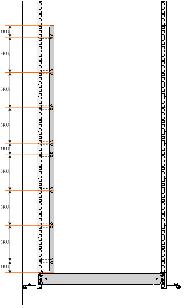
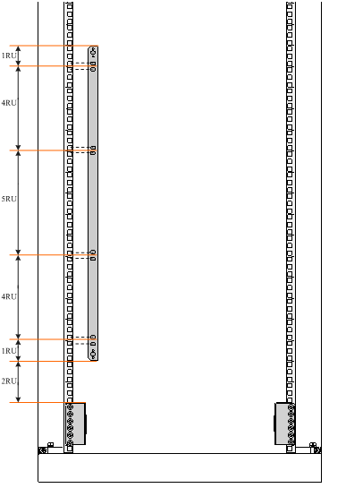
Figure2-19 Marking cage nut installation holes for attaching mounting brackets (for the S12512X-AF switch)
Mounting the switch in a rack
|
|
CAUTION: · Hold the chassis handles to move the switch. The S12502X-AF does not have any chassis handles. To move an S12502X-AF, support the switch bottom from both sides. Do not hold the handle of a fan tray, a power module, or a card, or the air vents of the chassis to carry the switch. Any attempt to carry the switch with these parts might cause equipment damage or even bodily injury. · Remove the fan trays, power modules, and filler panels from the switch before lifting. Reinstall these components after installing the switch in the rack. · Do not place your hand into any slot when you move the chassis. |
|
|
IMPORTANT: · The switch is heavy. As a best practice, use a mechanical lift, such as forklift truck, to move and carry the switch to the rack. · If no mechanical lift is used, cooperate with a minimum of four people to manually lift the switch. |
Rack-mounting the S12501X-AF switch
1. Orient the chassis with its rear facing towards the front of the rack.
2. Align the chassis rails with the slide rails on the rack posts. Slide the chassis into the rack along the slide rails until the mounting brackets are flush against the rack posts.
3. Use the M6 screws provided with the switch to secure the mounting brackets to the rack.
The name plate of the chassis covers the middle two mounting screw holes in the right mounting brackets. Screw installation is not needed for these two mounting holes.
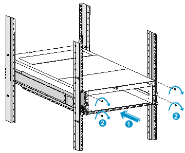
Figure2-24 Mounting the S12501X-AF switch in a rack
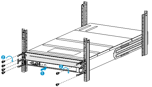
|
(1) Slide the chassis steadily into the rack along the guide rails |
|
(2) Use screws to secure the mounting brackets to the rack |
Rack-mounting other S12500X-AF switch models
1. Orient the chassis with its rear facing towards the front of the rack.
2. Lift the chassis until the switch bottom is a little higher than the slide rails on the rack.
3. Pace the switch on the slide rails and slide the switch into the rack along the slide rails until the mounting brackets are flush against the front rack posts, as shown by callout 2 in Figure2-25, Figure2-26, Figure2-27, Figure2-28, and Figure2-29, for the S12516X-AF, S12512X-AF, S12508X-AF, S12504X-AF, and S12502X-AF switches, respectively.
After placing the switch on the slide rails, do not leave go of your hands immediately because this might tip the switch, damaging the switch or even causing bodily injury.
4. Use M6 screws provided with the switch to attach the mounting brackets to the rack posts.
For the S12516X-AF, S12512X-AF, and S12508X-AF switches, the name plate on the upper right corner of the front panel covers two mounting screw holes in the mounting brackets. Screws are not needed for these two mounting holes.
If the mounting holes in the mounting brackets cannot align with the cage nuts on the rack, verify the following items:
¡ The top flange of the slide rail aligns with the middle of the narrower metal area between holes.
¡ The cage nuts are installed in the correct holes.
Figure2-25 Mounting the S12516X-AF switch in the rack
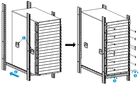
|
(1) Chassis handle |
(2) Slide the chassis into the rack |
|
(3) Use M6 screws to secure the mounting brackets to the rack |
|
Figure2-26 Mounting the S12512X-AF switch in the rack
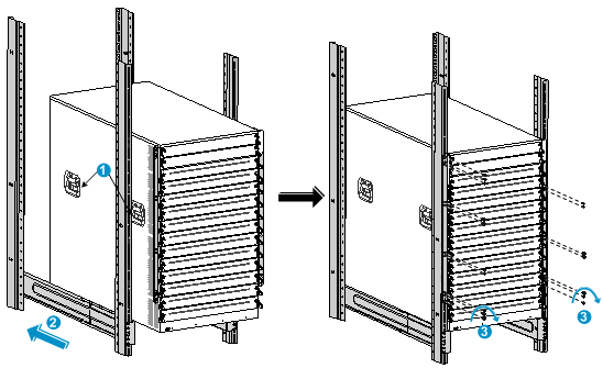
|
(1) Chassis handle |
(2) Slide the chassis into the rack |
|
(3) Use M6 screws to secure the mounting brackets to the rack |
|
Figure2-27 Mounting the S12508X-AF switch in the rack
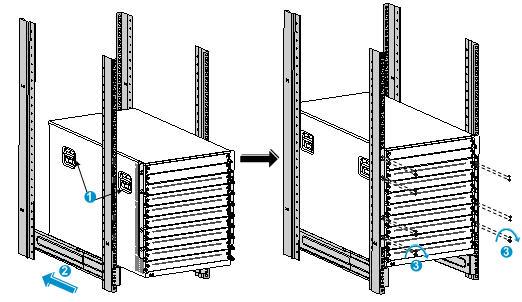
|
(1) Chassis handle |
(2) Slide the chassis into the rack |
|
(3) Use M6 screws to secure the mounting brackets to the rack |
|
Figure2-28 Mounting the S12504X-AF switch in the rack
|
(1) Chassis handle |
(2) Slide the chassis into the rack |
|
(3) Use M6 screws to secure the mounting brackets to the rack |
|
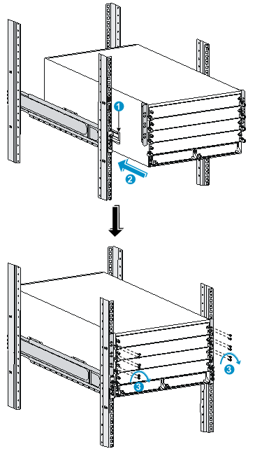
Figure2-29 Mounting the S12502X-AF switch in the rack
|
(1) Slide the chassis into the rack |
(2) Use M6 screws to secure the mounting brackets to the rack |
Grounding the switch
|
|
CAUTION: · Reliably grounding the switch is crucial to lightning protection and EMI protection. Ground the switch reliably before you use it. · Use the grounding cable (yellow-green grounding cable) provided with the switch. · Connect the grounding cable to the earthing system in the equipment room. Do not connect it to a fire main or lightning rod. |
|
|
IMPORTANT: As a best practice, fasten the grounding screws to a torque of 30 kgf-cm (2.94 Nm). |
You can ground the switch by connecting the grounding cable to a grounding strip in the equipment room or the grounding strip on the rack.
To connect the grounding cable to a grounding strip:
1. Unpack the grounding cable.
The grounding cable provided with the switch is compliant with the NEBS standards. The two-hole grounding lug of the grounding cable is used for connecting the chassis. The ring terminal of the grounding cable is used for connecting the grounding strip.
2. Remove the grounding screws from the grounding holes at the rear of the chassis.
A grounding sign is provided with the grounding holes, as shown by callout 2 in Figure2-30.
3. Use grounding screws to attach the two-hole grounding lug of the grounding cable to the chassis, as shown by callout 1 in Figure2-30.
|
|
IMPORTANT: For an S12501X-AF switch, attach the two-hole grounding lug to the chassis as shown in Figure2-31 so that the grounding cable is on top of the grounding lug. |
4. Connect the ring terminal of the grounding cable to a grounding post of the grounding strip, and fasten the grounding cable to the grounding strip with the hex nut.
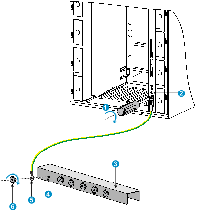
Figure2-30 Connecting the grounding cable to a grounding strip
|
(1) Use the grounding screws to attach the two-hole grounding lug to the grounding point |
||
|
(2) Grounding sign |
(3) Grounding strip |
(4) Grounding post |
|
(5) Ring terminal |
(6) Hex nut |
|
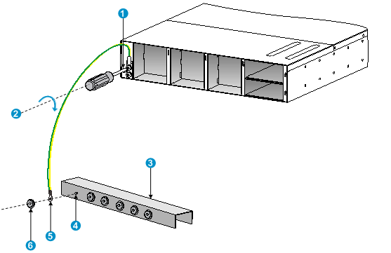
Figure2-31 Connecting the grounding cable to a grounding strip for an S12501X-AF switch
|
(1) Grounding sign |
(2) Use grounding screws to attach the two-hole grounding lug to the grounding point |
||
|
(3) Grounding strip |
(4) Grounding post |
(5) Ring terminal |
(6) Hex nut |
