- Table of Contents
-
- H3C S12500X-AF Switch Series Installation Guide-6W115
- 00-Preface
- 01-Chapter 1 Preparing for Installation
- 02-Chapter 2 Installing the Switch
- 03-Chapter 3 Installing FRUs
- 04-Chapter 4 Setting Up an IRF Fabric
- 05-Chapter 5 Connecting Your Switch to the Network
- 06-Chapter 6 Troubleshooting
- 07-Chapter 7 Replacement Procedures
- 08-Appendix A Engineering labels
- 09-Appendix B Cabling Recommendations
- 10-Appendix C Repackaging the Switch
- Related Documents
-
| Title | Size | Download |
|---|---|---|
| 06-Chapter 6 Troubleshooting | 549.87 KB |
No display on the configuration terminal
Garbled display on the configuration terminal
System failures during operation
Switching fabric module failure
6 Troubleshooting
This chapter describes how to troubleshoot your switch.
|
|
TIP: · Noncompliant operating environment might cause switch failure. You need to clean your switch periodically and make sure the installation environment meets the requirements. For more information, see "Preparing for installation." · Periodically perform power-on test on spare switches. |
Troubleshooting methods
When your switch fails, you can use the following methods to troubleshoot the switch:
· At the CLI, you can use related commands to display hardware information, and locate hardware failures.
· Every MPU provides LEDs for the fans, power modules, and cards. You can locate the failures according to the LED status on the MPU. For more information about the LED status on the MPU, see H3C S12500X-AF Switch Series Hardware Reference.
· The MPUs and LPUs provide port status LEDs, with which you can detect port failures. For more information about port status LEDs, see H3C S12500X-AF Switch Series Hardware Reference.
If you cannot locate failures by following the guidelines in this chapter, contact the local agents or technical support engineers. For more information, see "Technical support."
System failures at startup
No display on the configuration terminal
Symptom
The configuration terminal does not have display when the switch is powered on.
Solution
To resolve the issue:
1. Verify that the power system is operating correctly.
2. Verify that the MPU is operating correctly.
3. Verify that the console cable connects the console port on the MPU and the serial port on the terminal correctly.
4. Verify that the console cable is in good quality and is operating correctly.
5. Verify that the following settings are configured for the terminal:
¡ Baud rate—9600.
¡ Data bits—8.
¡ Parity—None.
¡ Stop bits—1.
¡ Flow control—None.
¡ Emulation—VT100.
6. If the issue persists, contract H3C support.
Garbled display on the configuration terminal
Symptom
The configuration terminal displays garbled text when the switch is powered on.
Solution
To resolve the issue:
1. Verify that the following settings are configured for the terminal:
¡ Baud rate—9600.
¡ Data bits—8.
¡ Parity—None.
¡ Stop bits—1.
¡ Flow control—None.
¡ Emulation—VT100.
2. If the issue persists, contact H3C Support.
System failures during operation
Symptom
A system failure occurs when the switch is operating.
Solution
To resolve the issue:
1. Execute related commands to locate the fault.
2. If a configuration error is found, re-configure the switch or restore the factory-default settings.
For more information, see H3C S12500-X&S12500X-AF Switch Series Fundamentals Configuration Guide.
3. If the issue persists, contact H3C Support.
Power module failure
Symptom
The LEDs for the power module are in the following states:
· On the MPU:
¡ For an MPU with two power module LEDs (OK and FAIL), the OK LED is off and the FAIL LED is on.
The power module OK LED is on and the FAIL LED is off only when all the power modules are operating correctly. When a power module is faulty, the OK LED is off and the FAIL LED is on.
¡ For an MPU with only one power module LED, the power module LED is steady red.
The power module LED is steady green only when all the power modules are operating correctly. When a power module is faulty, the power module LED is steady red.
· On the power module, the input LED is off, or the output LED is red.
|
|
NOTE: After a power module is disconnected from its power source, the input and output LEDs on the power module stay on for several seconds. |
Solution
To resolve the issue:
1. Verify that the power module model is compatible with the switch.
¡ The PSR2400-54A, PSR3000-54A, PSR2400-54D, and PSR3000-54AHD power modules are compatible with the S12516X-AF, S12512X-AF, S12508X-AF, S12504X-AF, and S12501X-AF switches.
¡ The PSR1800-56A and PSR1800-56D power modules are compatible with the S12502X-AF switch.
2. Remove and reconnect the power cord to verify that the power cord is connected securely.
3. Replace the power cord.
4. Remove and reinstall the power module to verify that it is installed securely.
For more information, see "Installing FRUs."
5. Verify that the power source is supplying power at the acceptable voltage range.
6. Verify that the total maximum output power of all power modules exceeds the system power consumption.
7. Verify that the power module does not have issues such as output short-circuit, output over-current, output over-voltage, input under-voltage, or over-temperature.
8. Install the power module in another empty power module slot. If the power module operates correctly, the previous power module slot is faulty. If the power module does not operate correctly, go to the next step.
9. Install a correctly operating power module of the same model in the same slot, and connect it to the same power source. If the new power module can operate correctly, the old power module has failed. Contact your sales agent or local service engineer to replace the old power module.
10. If the issue persists, contact H3C Support.
Fan tray failure
Symptom
The LEDs for the fan tray are in the following states:
· On the MPU:
¡ For an MPU with two fan tray LEDs (OK and FAIL), the OK LED is off and the FAIL LED is on.
¡ For an MPU with only one fan tray LED, the fan tray LED is steady red.
· On the fan tray, the OK LED is off and the FAIL LED is on.
Solution
To resolve the issue:
1. If all the LEDs are off, verify that the power modules are operating correctly. For more information, see "Power module failure."
2. Execute the display fan command in any view to display the operating state of the fan tray and rectify the fault:
¡ Whether the fan tray is present.
¡ Airflow direction of the fan.
¡ Number of fans in the fan tray.
¡ Operating status of each fan.
¡ Fan speed.
3. Verify that the air inlet and exhaust vents of the chassis are not blocked. If they are blocked, clean them to keep good ventilation.
4. Remove and reinstall the fan tray to make sure it is installed securely in the slot.
5. Verify that the empty LPU slots and power module slots are installed with filler panels. Install filler panels in empty slots.
6. Replace the fan tray.
7. If the issue persists, contact H3C Support.
MPU failure
Symptom
The MPU is operating incorrectly and its LED status is as follows:
· For an MPU with two card status LEDs (RUN and ALM) for each module, the RUN LED for the MPU is off.
· For an MPU with only one card status LED for each module, the LED for the MPU is steady red or flashing red.
Solution
To resolve the issue:
1. Verify that the power system is operating correctly. For more information, see "Power module failure."
2. Remove and reinstall the MPU to make sure it is installed securely. For more information, see "Installing FRUs."
3. Press the RESET button on the MPU to reset the MPU. After the MPU is reset, verify that the corresponding RUN LED is on or the MPU LED is flashing green.
4. If the switch has empty MPU slots, install the MPU in the empty MPU slot, and verify that the MPU can operate correctly.
5. If the issue persists, contact H3C Support.
|
|
NOTE: · On the S12516X-AF, S12512X-AF, S12508X-AF, and S12502X-AF switches, the MPU and LPU slot numbers are marked on the ejector lever seats at the left and right sides of the slots. The switching fabric module slot number is marked above the slot. · On the S12504X-AF switch, the MPU slot number is marked on the left side of the slot. The LPU slot number is marked on the ejector lever seats at the left and right sides of the slot. You can see the switching fabric module slot numbers through the openings in the fan trays, as shown by callout 3 and callout 6 in the Figure6-1. |
LPU failure
Symptom
An LPU is operating incorrectly and its LED status is as follows:
· For an MPU with two card status LEDs (RUN and ALM) for each module, the RUN LED for the LPU is off.
· For an MPU with only one card status LED for each module, the LED for the LPU is steady red or flashing red.
Solution
To resolve the issue:
1. Verify that the MPU is operating correctly. For more information, see "MPU failure."
2. Verify that the system software is compatible with the LPU. Upgrade the system software if it is not compatible with the LPU.
3. Calculate the total power consumption, and make sure your power modules can provide enough power. For more information, see H3C S12500X-AF Switch Series Hardware Reference.
4. Remove and reinstall the LPU to make sure it is installed securely. For more information about installing an LPU, see "Installing FRUs."
5. If the switch has empty LPU slots, install the card in an empty LPU slot. If the LPU operates correctly, the previous slot is faulty.
6. If the issue persists, contact H3C Support.
Switching fabric module failure
Symptom
The LEDs for the switching fabric module are in the following states:
· On the MPU:
¡ For an MPU with two card status LEDs (RUN and ALM) for each module, the RUN LED for the switching fabric module is off.
¡ For an MPU with only one card status LED for each module, the RUN LED for the switching fabric module is steady red or flashing red.
· On the fan tray, the RUN LED for the switching fabric module is off.
¡ On the S12516X-AF, S12512X-AF, and S12508X-AF fan trays, the RUN and ALM LED pairs correspond to the switching fabric module slots from left to right.
¡ On the S12504X-AF fan tray, the extended lines of the RUN and ALM LED pairs correspond to the switching fabric module slots from left to right.
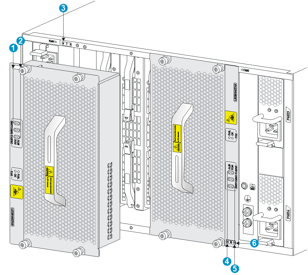
|
(1) LEDs for the switching fabric module slot 6 |
(2) LEDs for the switching fabric module slot 8 |
|
(3) Switching fabric module slot number |
(4) LEDs for the switching fabric module slot 9 |
|
(5) LEDs for the switching fabric module slot 11 |
(6) Switching fabric module slot number |
· On the switching fabric module, the RUN/ALM LED is red.
Solution
To resolve the issue:
1. Verify that the MPU and the fan tray are operating correctly. For more information, see "MPU failure" and "Fan tray failure."
2. Verify that the system software is compatible with the switching fabric module. Upgrade the system software if it is not compatible with the switching fabric module.
3. Calculate the total power consumption, and make sure your power modules can provide enough power. For more information, see H3C S12500X-AF Switch Series Hardware Reference.
4. Remove and reinstall the switching fabric module to make sure the module is installed securely. You also need to verify that the ejector levers are locked securely in place. For more information, see "Installing FRUs."
5. If the switch has empty switching fabric module slots, install the module in an empty switching fabric module slot. If the module operates correctly, the previous slot is faulty.
6. If the issue persists, contract H3C Support.
Interface failure
Symptom
The LED for the interface is off.
|
|
NOTE: A management Ethernet port has two LEDs, LINK and ACT. When the LINK LED is off, the management Ethernet port fails. |
Solution
To resolve the issue:
1. Make sure the MPU or LPU where the interface resides operates correctly. For more information, see "MPU failure" or "LPU failure."
2. Verify that the cable is connected correctly. For how to correctly connect a cable, see "Connecting your switch to the network."
3. Verify that the cable is in good condition. Use the cable to connect two interfaces of the same type that operate correctly. If the LEDs of the two interfaces are on, the cable is in good condition. Otherwise, the cable is faulty. Use a compliant cable to connect the interface. For more information, see H3C S12500X-AF Switch Series Hardware Reference.
4. If the interface uses a transceiver module, perform the following tasks:
a. Make sure the interface type is compatible with the transceiver and that the transceiver is compatible with the cable. For more information, see H3C S12500X-AF Switch Series Hardware Reference.
b. Replace the transceiver module.
5. Verify that the speed and duplex settings of the interfaces on the two ends are the same.
6. If the issue persists, contact H3C Support.
|
|
NOTE: · If an interface is brought down by the shutdown command, use the undo shutdown command to bring up the interface. · After an interface fails, if the switch has an idle interface of the same type, you can connect the cable to the idle interface. |
Technical support
Before contacting H3C Support, prepare the following information:
· Arrival time of the switch.
· Serial number of the chassis (on the label at the right of the rear panel).
· Software version, which you can view by using the display version command.
· Maintenance agreement or warranty card.
· Brief issue description.
· Brief explanation of the troubleshooting measures that have been taken.
