- Table of Contents
-
- H3C S12500X-AF Switch Series Installation Guide-6W115
- 00-Preface
- 01-Chapter 1 Preparing for Installation
- 02-Chapter 2 Installing the Switch
- 03-Chapter 3 Installing FRUs
- 04-Chapter 4 Setting Up an IRF Fabric
- 05-Chapter 5 Connecting Your Switch to the Network
- 06-Chapter 6 Troubleshooting
- 07-Chapter 7 Replacement Procedures
- 08-Appendix A Engineering labels
- 09-Appendix B Cabling Recommendations
- 10-Appendix C Repackaging the Switch
- Related Documents
-
| Title | Size | Download |
|---|---|---|
| 03-Chapter 3 Installing FRUs | 10.12 MB |
Installing MPUs for the S12516X-AF, S12512X-AF, and S12508X-AF switches
Installing MPUs for the S12504X-AF switch
Installing MPUs for the S12502X-AF switch
Installing cable management brackets
Installing switching fabric modules
Installing a filler panel in a switching fabric module slot
Removing a filler panel from a switching fabric module slot
Installing fan trays for S12516X-AF, S12512X-AF, and S12508X-AF switches
Installing fan trays for an S12504X-AF switch
Installing fan trays for an S12502X-AF switch
Installing fan trays for an S12501X-AF switch
Installing transceiver modules
Installing an SFP+/SFP/QSFP+/QSFP28/QSFP-DD transceiver module
Installing a CFP2 transceiver module
Installing a CXP transceiver module
Connecting an SFP+/QSFP+/QSFP28/QSFP-DD/QSFP+ to SFP+ copper cable
3 Installing FRUs
As a best practice, connect power cords after installing all required FRUs. To ensure good ventilation, install filler panels on unused slots.
Long-time exposure to strong air flow might cause discomfort. To avoid this hazard, do not stand close to the air outlet vents while the switch is operating. If you must be next to the switch on the air outlet vent side for an extended period, avoid the air flow or take other protective measures.
|
|
TIP: Keep the chassis and the component packages for future use. |
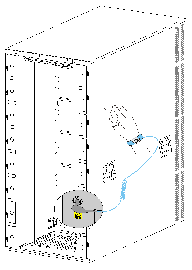
Attaching an ESD wrist strap
An S12501X-AF switch does not have an ESD jack and no ESD wrist strap is provided with it. Prepare an ESD wrist strap for the switch yourself and ground the strap reliably.
The other S12500X-AF switch models each are provided with an ESD wrist strap. To minimize ESD damage to electronic components, wear the ESD wrist strap and make sure it is reliably grounded before you install FRUs.
To attach an ESD wrist strap:
1. Make sure the switch is reliably grounded. For information about how to ground your switch, see "Installing the switch."
2. Put on the wrist strap.
3. Tighten the wrist strap to make sure it makes good skin contact. Make sure the resistance reading between your body and the ground is between 1 and 10 megohms.
4. As shown in Figure3-1, insert the ESD wrist strap into the ESD jack on the chassis.
Figure3-1 Attaching an ESD wrist strap (S12516X-AF switch)
|
(1) ESD jack (with an ESD sign) |
Installing MPUs
|
|
CAUTION: · If you are not to install an MPU in an MPU slot, keep the filler panel in the slot. · Before you install an MPU in the chassis, make sure the connectors on the MPU are not broken or blocked. · When you install an MPU, avoid damaging the connectors on the MPU. · To prevent a filler panel from being drawn into the chassis when fan speed is high, use both hands to grasp the filler panel by its two sides during filler panel installation and removal on an operating switch. |
|
|
IMPORTANT: As a best practice, fasten the captive screws to a torque of 5 kgf-cm (0.49 Nm). |
An S12501X-AF switch does not require MPUs.
Unless otherwise stated, the term "MPU" in this document refers to MPUs and cloud SEUs.
For the compatibility between the switch and the MPUs, see H3C S12500X-AF Switch Series Hardware Reference.
You can install one MPU, or two MPUs for redundancy on the switch. If you are to install one MPU, install it in either of the MPU slots.
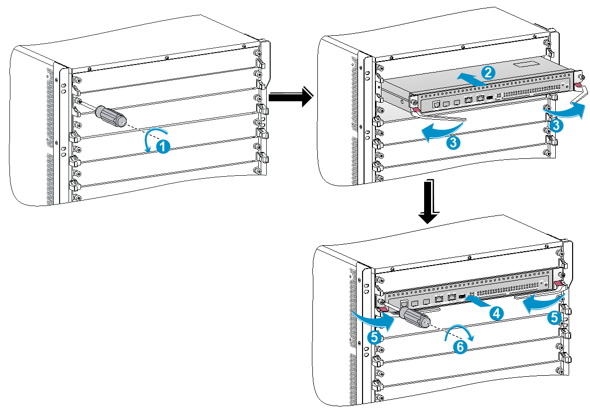
Installing MPUs for the S12516X-AF, S12512X-AF, and S12508X-AF switches
For the S12516X-AF, S12512X-AF, and S12508X-AF switches, the ejector levers of the MPUs and the ejector lever seats on the MPU slots have pink marks. The MPU installation procedure is the same for the S12516X-AF, S12512X-AF, and S12508X-AF switches. The following uses the S12516X-AF switch as example.
To install an MPU:
1. As shown by callout 1 in Figure3-2, remove the filler panel from the target MPU slot.
Keep the removed filler panel secure for future use.
2. As shown by callout 2 in Figure3-2, orient the MPU with lettering on it upright. Hold the MPU by the front panel with one hand and support the bottom with the other. Push the MPU steadily into the slot along the guide rails.
Keep the MPU parallel to the slot to avoid touching other components in the chassis.
3. As shown by callout 3 in Figure3-2, pull the ejector levers of the MPU outward when most part of the MPU is inserted in the slot.
4. Push the MPU until the brakes on its ejector levers touch the slot edges tightly.
5. As shown by callout 4 in Figure3-2, Continue to push the MPU by its middle part on the front panel until you cannot move it.
6. As shown by callout 5 in Figure3-2, push the ejector levers inward until they come in close contact with the front panel.
7. As shown by callout 6 in Figure3-2, fasten the captive screws on the MPU.
Figure3-2 Installing an MPU (S12516X-AF switch)
|
(1) Loosen the captive screws and remove the filler panel |
(2) Insert the MPU into the slot |
|
(3) Pull the ejector levers outward |
|
|
(4) Push the MPU by the middle part on the front panel |
|
|
(5) Pull the ejector levers inward |
(6) Fasten the captive screws on the MPU |
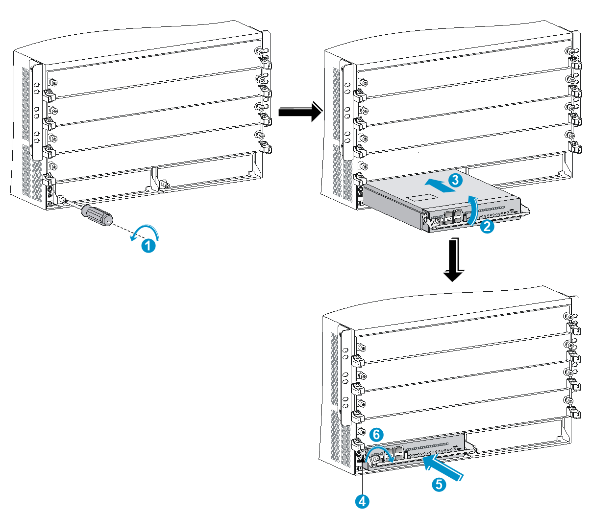
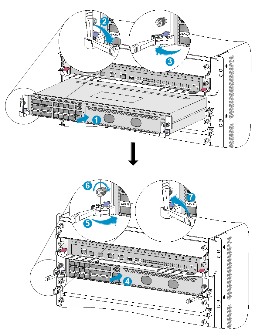
Installing MPUs for the S12504X-AF switch
The S12504X-AF switch MPU marks and MPU slot edges are pink-marked.
To install an MPU for the S12504X-AF switch:
1. As shown by callout 1 in Figure3-3, remove the filler panel from the target MPU slot.
Keep the removed filler panel secure for future use.
2. As shown by callout 2 in Figure3-3, pivot up the handle of the MPU.
3. As shown by callout 3 in Figure3-3, orient the MPU lettering on it upright. Holding the MPU by the front panel with one hand and supporting the bottom with the other, push the MPU steadily into the slot along the guide rails.
Keep the MPU parallel to the slot to avoid touching other components in the chassis.
4. As shown by callout 4 in Figure3-3, push the MPU until the handle breaks touch the slot edges tightly.
5. As shown by callout 5 in Figure3-3, continue to push the MPU handle until the MPU is secure in position.
6. Fasten the captive screws on the MPU.
Figure3-3 Installing an MPU (S12504X-AF switch)
|
(1) Loosen the captive screws and remove the filler panel |
|
|
(2) Pivot up the handle |
|
|
(3) Push the MPU into the slot along the guide rails |
|
|
(4) Push the MPU until the handle breaks touch the slot edges tightly |
|
|
(5) Push the handle until the MPU is secure in position |
(6) Fasten the screws on the MPU |
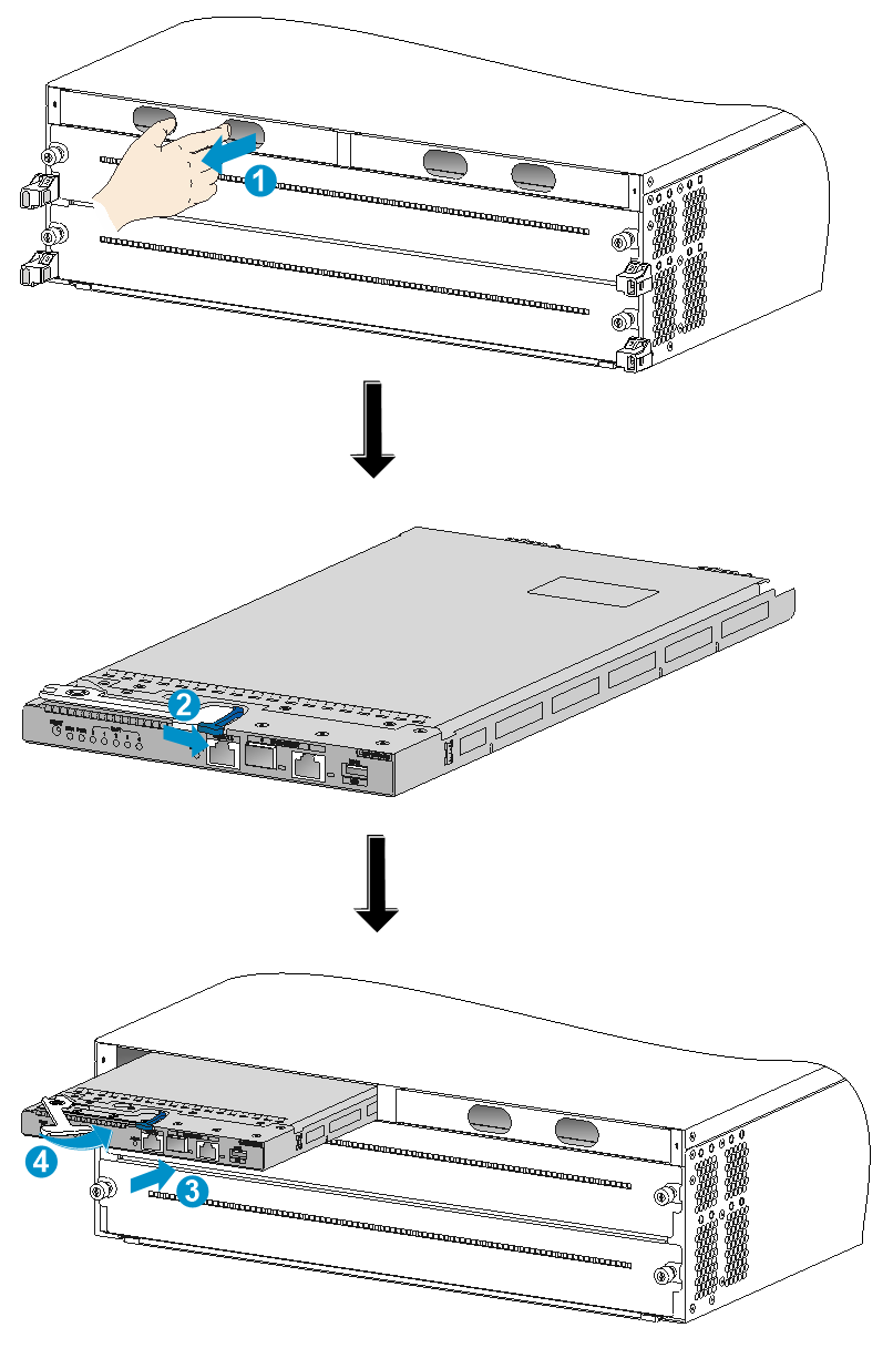
Installing MPUs for the S12502X-AF switch
The S12502X-AF switch MPU has pink marks.
To install an MPU for the S12502X-AF switch:
1. As shown by callout 1 in Figure3-4, remove the filler panel from the target MPU slot.
Keep the removed filler panel secure for future use.
2. As shown by callout 2 in Figure3-4, press the latch on the MPU to release the ejector lever. Fully open the ejector lever.
3. As shown by callout 3 in Figure3-4, orient the MPU with the upside up. Hold the MPU by the front panel with one hand and support the bottom with the other. Push the MPU steadily into the slot along the guide rails until it has firm contact with the slot.
Keep the MPU parallel to the slot to avoid touching other components in the chassis.
4. As shown by callout 4 in Figure3-4, close the ejector lever until the latch locks the ejector lever in place.
Installing LPUs
|
|
CAUTION: · Before you install an LPU on the switch, make sure the connectors on the LPU are not damaged or blocked. · To prevent a filler panel from being drawn into the chassis when fan speed is high, use both hands to grasp the filler panel by its two sides during filler panel installation and removal on an operating switch. |
|
|
CAUTION: To prevent card damage and ensure correct operation, LPUs can only be used with switching fabric modules of the same type. · Type T LPUs have a character T in their card identifier (for example, LSXM1CGQ36TD1). Type T switching fabric modules have a character string of SFT in their card identifier (for example, LSXM1SFT16E1). · Type H LPUs have a character of H in their card identifier (for example, LSXM1CGQ36HB1). Type H switching fabric modules have a character string of SFH in their card identifier (for example, LSXM1SFH16C1). · Type F LPUs have a character of F in their card identifier (for example, LSXM1CGP12FX1). Type F switching fabric modules have a character string of SFF in their card identifier (for example, LSXM1SFF16C1). |
|
|
IMPORTANT: As a best practice, fasten the captive screws to a torque of 5 kgf-cm (0.49 Nm). |
For the compatibility between the switch and the LPUs (also called interface modules), see H3C S12500X-AF Switch Series Hardware Reference.
The S12501X-AF and S12502X-AF switches support only S12500X-AF Type H LPUs.
Installing S12500-X LPUs
The S12500X-AF switch supports only FX and FE series S12500-X LPUs. To install an S12500-X LPU on the switch, first install an interface module adapter in the LPU slot.
|
|
CAUTION: For heat dissipation of the switch, you must install an LPU in the slot where an interface module adapter is installed. If you are not to install an LPU in the slot, remove the interface module adapter and install a filler panel. |
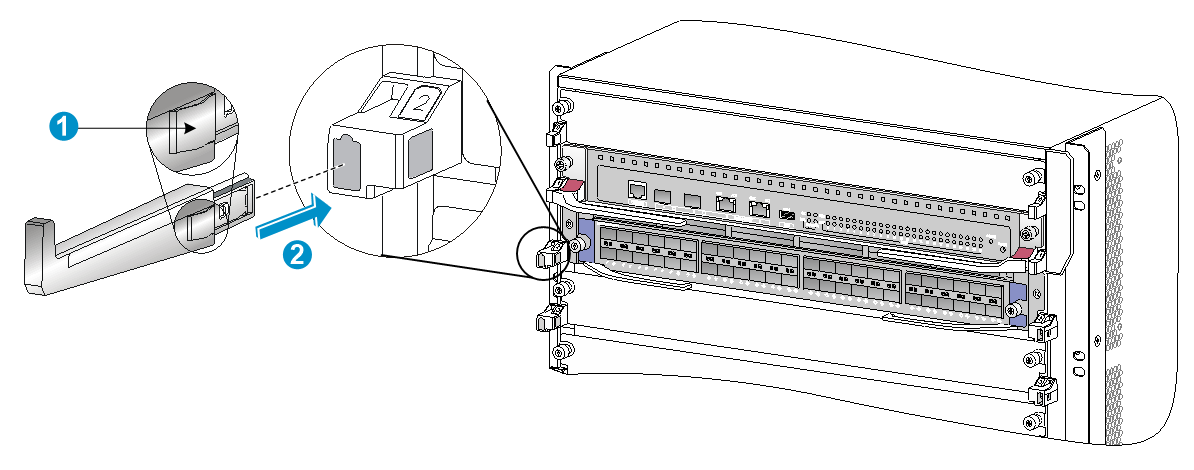
Installing an interface module adapter
1. Remove the filler panel from the target slot. See callout 1 in Figure3-2.
Keep the removed filler panel secure for future use.
2. As shown in Figure3-5, align the adapter rear with the LPU slot and push the adapter slowly along the guide rails into the slot.
3. As shown by callout 2 in Figure3-5, use the screws provided with the interface module adapter to secure the adapter to the chassis.
Figure3-5 Installing an interface module adapter (S12516X-AF switch)
|
(1) Push the interface module adapter slowly along the guide rails into the slot |
|
(2) Fasten the screws to secure the interface module adapter to the chassis |
Installing an S12500-X LPU
The S12500-X LPU edges and the ejector lever seats on the LPU slots have purple marks.
To install an S12500-X LPU:
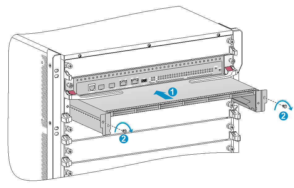
1. As shown in Figure3-6, loosen the captive screws that secure the LPU to the protection box, pull the ejector levers of the LPU outward, and pull out the LPU from the protection box. .
2. Orient the LPU with the PCB facing up. Hold the LPU by the front panel with one hand and support its bottom with the other. Slide the LPU steadily into the target slot along the guide rails. See Figure3-7.
Do not touch the components on the PCB.
Keep the LPU parallel to the slot to avoid touching other components in the chassis.
3. As shown by callout 2 in Figure3-7, pull the ejector levers outward when most of the LPU is inserted into the slot.
4. Push the LPU until the brakes on its ejector levers touch the slot edges tightly.
5. As shown by callout 3 in Figure3-7, continue to push the LPU by its middle part on the front panel until you cannot move it.
6. As shown by callout 4 in Figure3-7, push the ejector levers inward until they come in close contact with the panel.
7. As shown by callout 5 in Figure3-7, fasten the captive screws to secure the LPU to the interface module adapter.
Figure3-6 Removing an S12500-X LPU from the protection box
|
(1) Loosen the captive screws that secure the LPU to the protection box |
|
(2) Pull the ejector levers outward |
|
(3) Pull the LPU out of the protection box |
Figure3-7 Installing an S12500-X LPU (S12516X-AF switch)
|
(1) Push the LPU slowly along the guide rails into the slot |
(2) Pull the ejector levers outward |
|
(3) Push the LPU by the middle part on the front panel |
(4) Pull the ejector levers inward |
|
(5) Fasten the captive screws on the LPU |
|
Installing S12500X-AF LPUs
|
|
CAUTION: · The S12501X-AF and S12502X-AF switches support only S12500X-AF Type H LPUs. · A protective blank panel is installed over LPU slots on the S12502X-AF to avoid damage during transportation. Before you install an LPU on the S12502X-AF, remove the protective blank panel first. |
|
|
IMPORTANT: Keep filler panels installed on unused LPUs. |
No interface module adapter is required to install an S12500X-AF LPU on the switch.
The S12500X-AF LPU ejector levers and the ejector lever seats on the LPU slots have purple marks.
Installing an LPU with common ejector levers
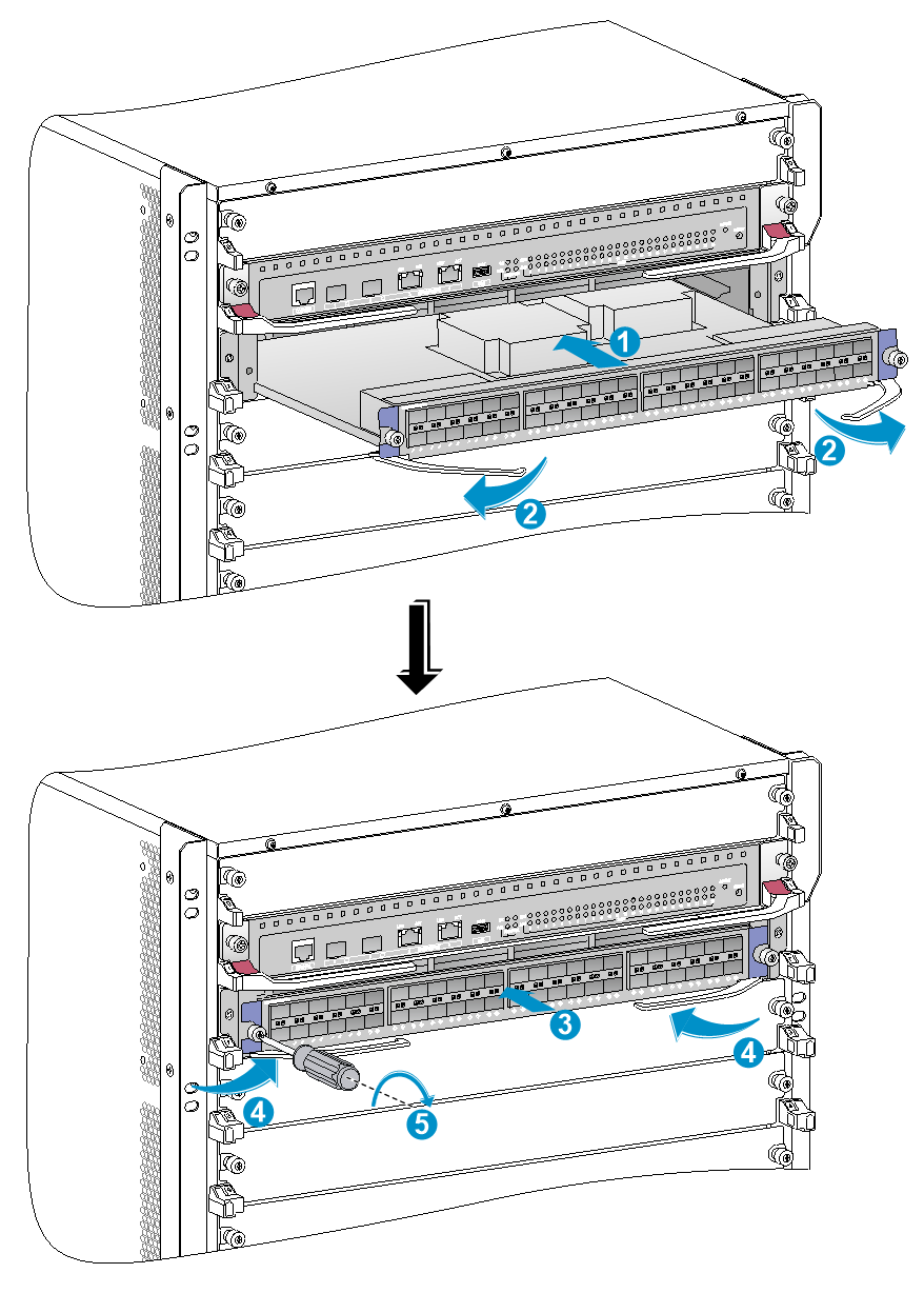
1. As shown by callout 1 in Figure3-8, remove the filler panel from the target LPU slot.
Keep the removed filler panel secure for future use.
2. As shown by Figure3-8, orient the LPU upside up based on the orientation of characters on the LPU. Holding the LPU by the front panel with one hand and supporting the bottom with the other, push the LPU steadily into the slot along the guide rails.
Keep the LPU parallel to the slot to avoid touching other components in the chassis.
3. As shown by callout 2 in Figure3-8, pull the ejector levers of the LPU outward when most part of the LPU is inserted in the slot.
4. Push the LPU until the brakes on its ejector levers touch the slot edges tightly.
5. As shown by callout 3 in Figure3-8, Continue to push the LPU by its middle part on the front panel until you cannot push it further.
6. As shown by callout 4 in Figure3-8, push the ejector levers inward until they come in close contact with the front panel.
7. As shown by callout 5 in Figure3-8, fasten the captive screws on the LPU.
Figure3-8 Installing an LPU with common ejector levers (S12516X-AF switch)
|
(1) Push the LPU slowly along the guide rails into the slot |
(2) Pull the ejector levers outward |
|
(3) Push the LPU by the middle part on the front panel |
(4) Pull the ejector levers inward |
|
(5) Fasten the captive screws on the LPU |
|
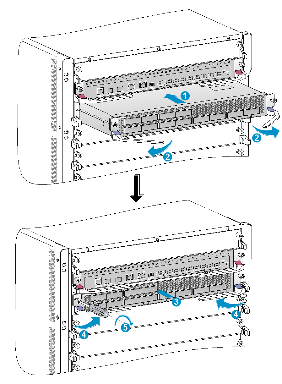
Installing an LPU with foldable ejector levers
1. Orient the LPU with the lettering on it upward.
2. As shown by callout 1 in Figure3-9, holding the LPU by the front panel with one hand and supporting its bottom with the other, slide the LPU gently into the slot along the slide rails.
Keep the LPU parallel to the slot to avoid damaging other components in the chassis.
3. When most part of the LPU is inserted into the slot, simultaneously pivot the ejector levers towards each other until they stop, as shown by callout 2 in Figure3-9.
4. As shown by callout 3 in Figure3-9, rotate the ejector levers away from the front panel until they stop.
5. As shown by callout 4 in Figure3-9, push the LPU by its middle part on the front panel until you cannot move it.
6. As shown by callout 5 in Figure3-9, push the ejector levers inward towards the front panel.
7. As shown by callout 6 in Figure3-9, fasten the captive screws to secure the LPU in the chassis.
8. As shown by callout 7 in Figure3-9, rotate the ejector levers upward to the vertically closed position.
Figure3-9 Installing an LPU with foldable ejector levers (S12516X-AF switch)
|
(1) Push the LPU slowly into the slot along the slide rails |
|
(2) Rotate the ejector levers towards each other until they stop |
|
(3) Rotate the ejector levers away from the front panel until they stop |
|
(4) Push the LPU by the middle part on the front panel |
|
(5) Push the ejector levers inward towards the front panel |
|
(6) Fasten the captive screws on the LPU |
|
(7) Rotate the ejector levers upward to the vertically closed position |
Installing cable management brackets
For an S12501X-AF switch, the cable management brackets come attached to the mounting brackets and do not require separate installation.
The cable management brackets are installed on the two sides of the LPU slots. As a best practice, install cable management brackets after you have installed LPUs.
As shown in Figure3-10, insert the cable management bracket end that has a spring tab into the cable management bracket hole until the bracket has close contact with the hole.
Figure3-10 Installing a cable management bracket (S12516X-AF switch)
|
(1) Spring tab on the cable management bracket |
|
(2) Align the cable management bracket with the bracket hole |
|
|
NOTE: You must press the spring tab while removing a cable management bracket. |
Installing switching fabric modules
|
|
CAUTION: Do not use switching fabric modules of different models on the same switch. To use new types of switching fabric modules, replace all switching fabric modules with new ones and then reboot the system. |
|
|
CAUTION: · Before you install a switching fabric module on the switch, make sure the connectors on the switching fabric module are not damaged or blocked. · When you install a switching fabric module, avoid damaging the connectors on it. · Install switching fabric modules or switching fabric module slot filler panels before you install the fan tray. · Install filler panels in the empty switching fabric module slots. · To replace or install a switching fabric module for an operating device, first remove the fan tray that covers the slot of the switching fabric module. Install the fan tray immediately after the replacement or installation. After the fan tray starts operating, you can replace or install switching fabric modules whose slots are covered by the other fan tray. · The smart speed adjustment feature increases the fan speed when only one fan tray is operating. Take noise protection measures such as wearing an earmuff or earplug. In addition, make good preparation before hot swapping a switching fabric module to minimize the operation time. |
|
|
CAUTION: The S12516X-AF, S12512X-AF, S12508X-AF, and S12504X-AF switches use slots 18 to 23, 14 to 19, 10 to 15, and 6 to 11 for switching fabric modules, respectively. · To use an LSXM1TGS24FX1 LPU, the three lowest-numbered switching fabric module slots take precedence over other slots for module installation. For an LSXM1TGS24FX1 LPU to start up correctly, install a minimum of one switching fabric modules in the three lowest-numbered switching fabric module slots. · To use an LSXM1TGS48C2HB1, LSXM1TGS48HB1, LSXM1TGS48HF1, LSXM1CGQ6QGHB1, LSXM1CGQ6QGHF1, or LSXM1TGS24QGMODHB1 LPU, the three highest-numbered switching fabric module slots take precedence over other slots for module installation. For the LPU to start up correctly, install a minimum of one switching fabric modules in the three highest-numbered switching fabric module slots. · To use an LSXM1QGS24HB1, LSXM1QGS36HB1, LSXM1TGS48QGHA1, or LSXM1TGS24CGMODHD1 LPU, the four highest-numbered switching fabric module slots take precedence over other slots for module installation. For the LPU to start up correctly, install a minimum of one switching fabric modules in the four highest-numbered switching fabric module slots. |
|
|
CAUTION: To prevent card damage and ensure correct operation, switching fabric modules can only be used with LPUs of the same type. · Type T switching fabric modules have a character string of SFT in their card identifier (for example, LSXM1SFT16E1). Type T LPUs have a character of T in their card identifier (for example, LSXM1CGQ36TD1). · Type H switching fabric modules have a character string of SFH in their card identifier (for example, LSXM1SFH16C1). Type H LPUs have a character of H in their card identifier (for example, LSXM1CGQ36HB1). · Type F switching fabric modules have a character string of SFF in their card identifier (for example, LSXM1SFF16C1). Type F LPUs have a character of F in their card identifier (for example, LSXM1CGP12FX1). |
The S12501X-AF and S12502X-AF switches do not require switching fabric modules.
For the compatibility between the switch and the switching fabric modules, see H3C S12500X-AF Switch Series Hardware Reference.
The switch has six vertically-oriented switching fabric module slots at the chassis rear. The switch comes with all switching fabric module slots empty. You can install two to six switching fabric modules for the switch. Install switching fabric module slot filler panels in the empty switching fabric module slots.
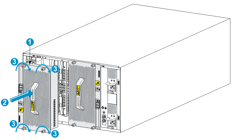
To install a switching fabric module:
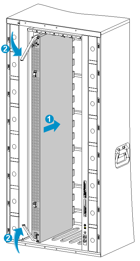
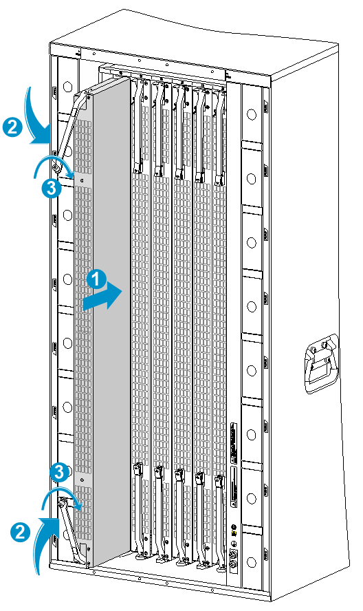
1. Place the switching fabric module on a workbench and remove the protection box from the connector side of the switching fabric module. See Figure3-11.
2. Release the ejector levers by pressing the spring clips.
3. Orient the switching fabric module with the side marked "Up" up. Hold the switching fabric module front panel near the ejector levers with one hand and support the module bottom with the other. Place the module bottom on the guide rails at the chassis bottom. Align the switching fabric module with the target slot and insert it into the slot along the guide rails. See callout 1 in Figure3-12.
Keep the module parallel to the slot to avoid touching other components in the chassis.
4. As shown by callout 2 in Figure3-12, continue to push the switching fabric module until the brakes on its ejector levers touch the slot edges tightly. Simultaneously rotate the ejector levers inward until the spring clips lock the ejector levers in place and the switching fabric module is completely seated in the slot.
Figure3-11 Removing the switching fabric module from the protection box (S12516X-AF switching fabric module)
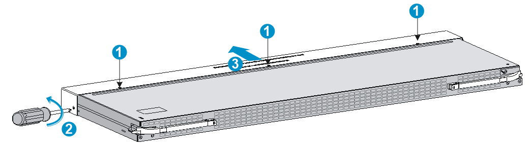
|
(1) Five screws to secure the protection box to the switching fabric module |
(2) Loosen the captive screws |
|
(3) Hold the protection box to disengage it from the connector side of the switching fabric module |
|
Figure3-12 Installing a switching fabric module (S12516X-AF switch)
|
(1) Push the switching fabric module slowly into the slot |
|
(2) Rotate the ejector levers inward until the spring clips lock the ejector levers in place |
Installing a filler panel in a switching fabric module slot
|
|
IMPORTANT: As a best practice, fasten captive screws to a torque of 5 kgf-cm (0.49 Nm). |
The switch comes with empty switching fabric module slots. Install a filler panel in a switching fabric module slot if you are not to install a switching fabric module in it.
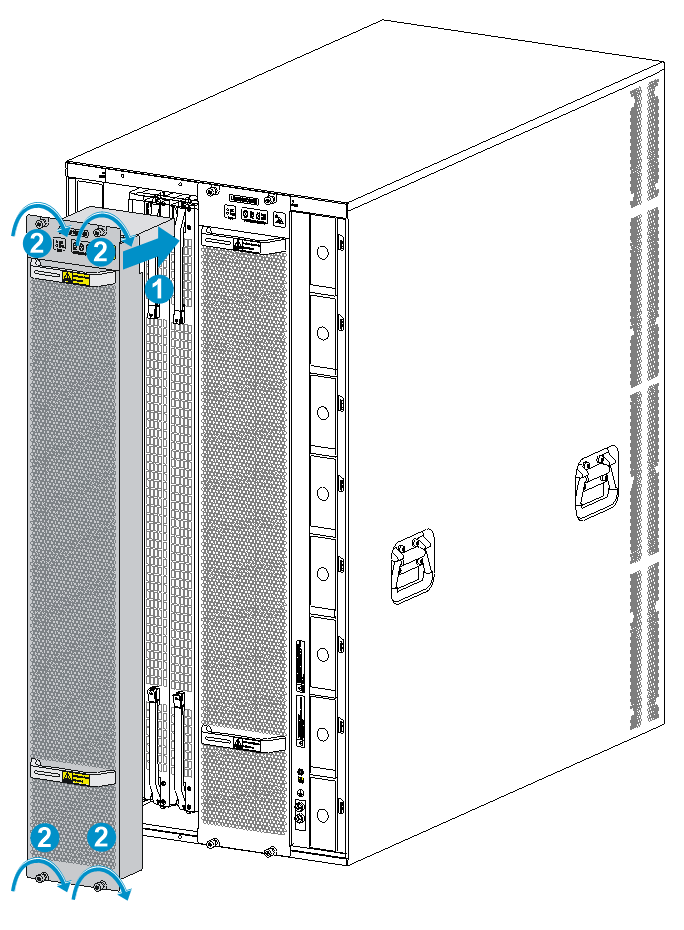
To install a filler panel in a switching fabric module slot:
1. Loosen the captive screws on the ejector levers and rotate outward the ejector levers.
2. Orient the filler panel with the side marked "Up" up. Hold the filler panel front panel near the ejector levers with one hand and support its bottom with the other. Place the filler panel bottom gently on guide rails at the chassis bottom. Align the filler panel with the switching fabric module slot. Push the filler panel slowly into the slot along the guide rails. See callout 1 in Figure3-13.
Keep the filler panel parallel to the switching fabric module slot to avoid touching other components in the chassis.
3. As shown by callout 2 in Figure3-13, continue to push the filler panel until the brakes on its ejector levers touch the slot edges tightly. Simultaneously rotate the ejector levers inward.
4. Fasten the captive screws on the ejector levers.
Figure3-13 Installing a filler panel in a switching fabric module slot (S12516X-AF switch)
|
(1) Push the filler panel slowly into the slot |
(2) Simultaneously rotate the ejector levers inward |
|
(3) Fasten the captive screws on the ejector levers |
|
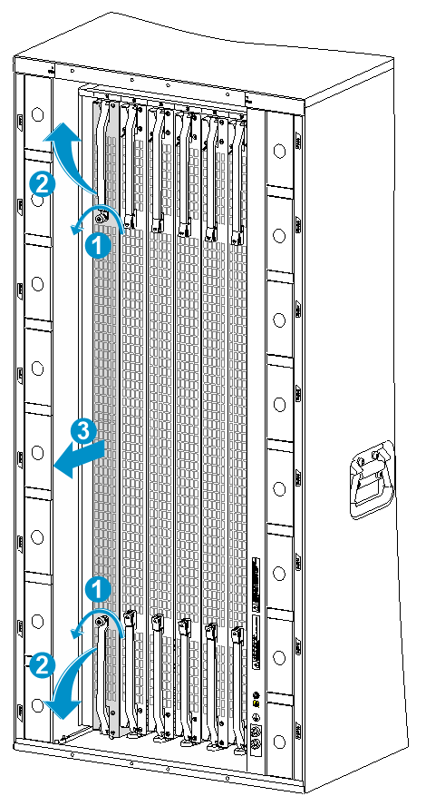
Removing a filler panel from a switching fabric module slot
1. As shown by callout 1 in Figure3-14, loosen the captive screws on the ejector levers.
2. As shown by callout 2 in Figure3-14, rotate outward the ejector levers. Then pull the filler panel part way out of the slot.
3. As shown by callout 3 in Figure3-14, hold the filler panel by the top and bottom edges to pull the filler panel out of the slot.
Keep the removed the filler panel secure for future use.
Figure3-14 Removing a filler panel from a switching fabric module slot (S12516X-AF switch)
|
(1) Loosen the captive screws on the ejector levers |
(2) Rotate the ejector levers outward |
|
(3) Pull the filler panel out of the slot along the guide rails |
|
Installing fan trays
|
|
WARNING! When removing the fan tray, keep your hands and fingers away from the spinning fan blades. Let the fan blades completely stop before you remove the fan tray. |
|
|
CAUTION: · To avoid fan tray damage, use both hands when installing or removing a fan tray. · To prevent dust from entering the chassis, make sure each fan tray slot has a filler panel or fan tray installed when the switch is not in use. |
|
|
CAUTION: When you hot swap fan trays, follow these guidelines: · Ensure electricity safety. · For an S12501X-AF switch, you can hot swap a fan tray only when the other two fan trays are operating correctly. For the other S12500X-AF switch models, you can hot swap a fan tray only when the other fan tray is operating correctly. · When you hot swap a fan tray, the fan speed of the remaining fan trays automatically increases. Take noise protection measures such as wearing an earmuff or earplug. In addition, make preparations before hot swapping a fan tray to minimize the operation time. |
|
|
IMPORTANT: A fan tray covers switching fabric module slots. Install switching fabric modules or filler panels in the switching fabric module slots before installing a fan tray. Make sure ejector levers of the switching fabric modules are locked in place by the spring clips, and the ejector levers of the filler panels are secured by captive screws. |
An S12501X-AF switch has three fan tray slots and supports 2+1 fan tray redundancy. The other S12500X-AF switch models each have two fan tray slots. You can install one fan tray, or two fan trays in 1+1 redundancy for the switch. As a best practice, install a fan tray in each slot for redundancy and to reduce noises.
Installing fan trays for S12516X-AF, S12512X-AF, and S12508X-AF switches
|
|
WARNING! The fan tray is high and heavy. To avoid device damage and bodily injury, use two people to install or remove a fan tray. |
|
|
IMPORTANT: As a best practice, fasten captive screws to a torque of 5 kgf-cm (0.49 Nm). |
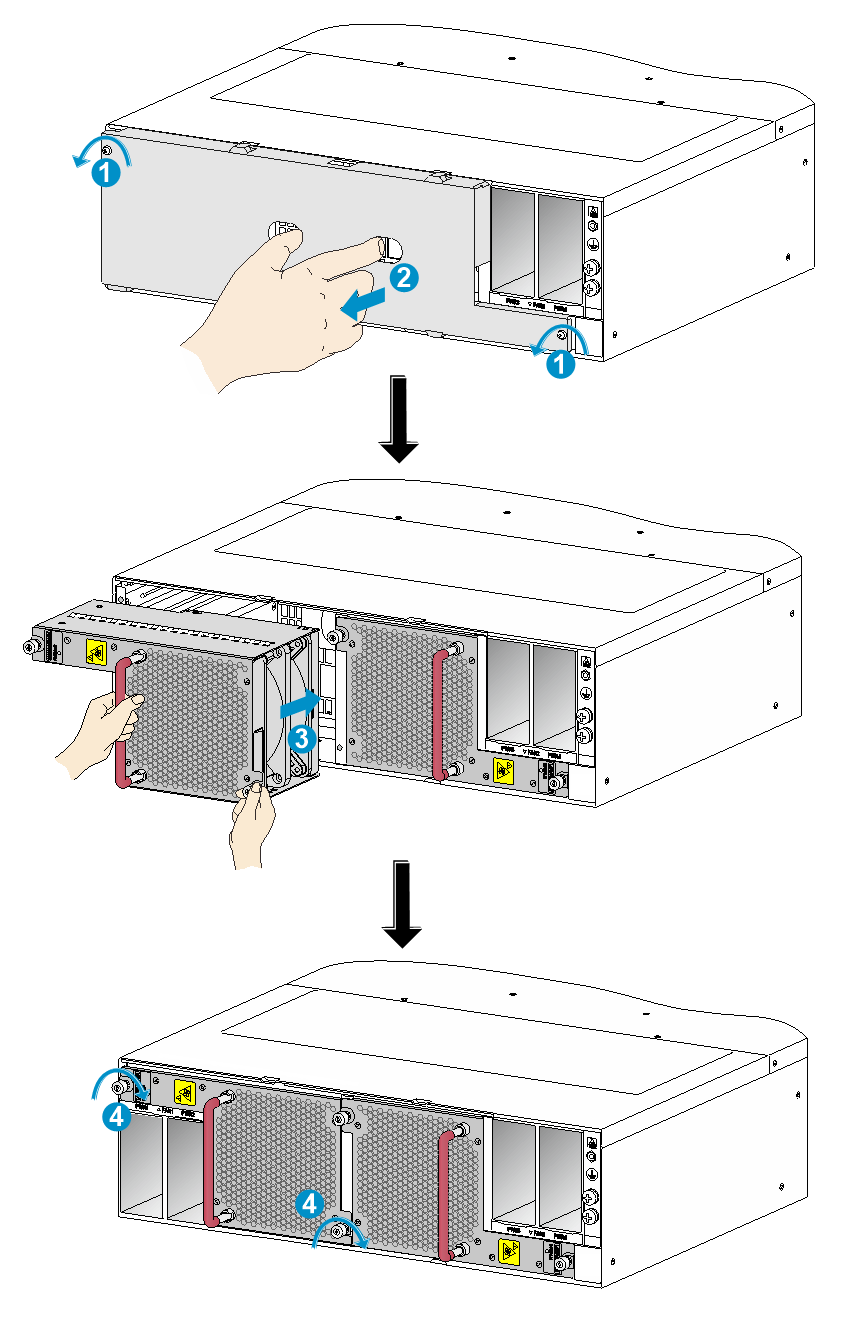
To install a fan tray for the S12516X-AF, S12512X-AF, or S12508X-AF switch:
1. Orient the fan tray with the upside up based on the orientation of characters on the fan tray and align the fan tray with the fan tray slot.
2. Holding the upper fan tray handle with one hand and the lower fan tray handle with the other hand, insert the fan tray into the slot. Keep the fan tray as straight as possible.
To install a fan tray in FAN1 slot, align the top and left edges of the fan tray in the slot. To install a fan tray in FAN2 slot, align the top and right edges of the fan tray in the slot.
3. Fasten the captive screws on the fan tray.
Figure3-15 Installing a fan tray (S12516X-AF switch)
|
(1) Align the fan tray with the fan tray slot |
(2) Fasten the captive screws |
Installing fan trays for an S12504X-AF switch
|
|
IMPORTANT: As a best practice, fasten captive screws to a torque of 5 kgf-cm (0.49 Nm). |
To install a fan tray for an S12504X-AF switch:
1. Orient the fan tray correctly.
To install a fan tray in the FAN1 slot, orient the fan tray so that the LEDs are on the left side of the front panel. To install a fan tray in the FAN2 slot, orient the fan tray so that the LEDs are on the right side of the front panel.
2. As shown by callout 1 in Figure3-16, align the positioning pin on the fan tray with the positioning hole in the chassis.
3. As shown by callout 2 in Figure3-16, hold the fan tray handle and insert the fan tray into the slot.
Keep the fan tray as straight and stable as possible while inserting it into the slot.
4. As shown by callout 3 in Figure3-16, fasten the captive screws on the fan tray.
Figure3-16 Installing a fan tray for the S12504X-AF switch
|
(1) Align the positioning pin on the fan tray with the positioning hole above the fan tray slot |
|
|
(2) Insert the fan tray into the chassis |
(3) Fasten the captive screws on the fan tray |
Installing fan trays for an S12502X-AF switch
|
|
CAUTION: To install a fan tray in slot FAN1, orient the fan tray so that the LED is on the left side of the front panel. To install a fan tray in slot FAN2, orient the fan tray so that the LED is on the right side of the front panel. |
|
|
IMPORTANT: As a best practice, fasten captive screws to a torque of 5 kgf-cm (0.49 Nm). |
The following procedure uses slot FAN1 as an example.
To install a fan tray in slot FAN1 for the switch:
1. As shown by callouts 1 and 2 in Figure3-17, remove the screws on the filler panel with a Phillips screwdriver. Supporting the bottom of the filler panel with one hand, use your thumb and forefinger of the other hand to hold the filler panel through the two holes and pull out the filler panel along the guide rails.
Keep the removed filler panel secure for future use.
2. Unpack the fan tray.
3. Orient the fan tray correctly.
4. Holding the fan tray handle with one hand and supporting the bottom of the fan tray with the other, steadily insert the fan tray part way into the slot. See callout 3 in Figure3-17.
Keep the fan tray as steady as possible while inserting it into the slot.
5. Squeezing the captive screw at the air vents side with one hand and holding the fan tray handle with the other, push the fan tray fully into the slot.
6. Fasten the captive screws on the fan tray. See callout 4 in Figure3-17
Figure3-17 Installing a fan tray
Installing fan trays for an S12501X-AF switch
The following procedure uses the FAN3 slot as an example.
To install a fan tray:
1. Unpack the fan tray.
2. As shown by callouts 1 and 2 in Figure3-18, orient the fan tray with the Top mark on the top. Grasping the handles of the fan tray with one hand and supporting the fan tray bottom with the other, slide the fan tray into the slot until it is fully seated in the slot and has firm contact with the backplane.
Figure3-18 Installing a fan tray
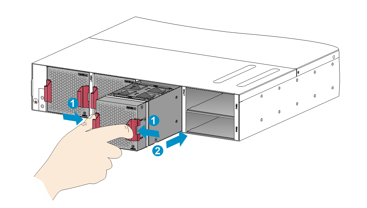
Installing power modules
On an S12501X-AF switch, the power module slots are located on the right of the rear panel. On the other S12500X-AF switch models, the power module slots are located on both sides of the rear panel.
The S12501X-AF and S12502X-AF switches are shipped with empty power module slots. Make sure the power modules slots have power modules or filler panels installed while the switch is operating.
The installation procedure is the same for DC and AC power modules.
To install a power module:
1. If a filler panel is installed in the slot, remove the filler panel first.
¡ For a filler panel as shown in Figure3-19, thread a flat-blade screwdriver through the hole in the handle of the filler panel and pull the filler panel out.
¡ For a filler panel as shown in Figure3-20, use your forefinger to hold the filler panel through the hole and pull out the filler panel along the guide rails.
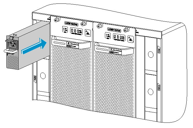
2. Correctly orient the power module.
If you install the power module in a left power module slot, make sure the latch is above the handle. If you install the power module in a right power module slot, make sure the latch is below the handle.
3. Holding the handle of the power module with one hand and supporting the bottom of the power module with the other, slide the power module along the guide rails into the slot until you hear a click.
The power module is foolproof. If the power module is oriented incorrectly, you cannot install the power module into the slot. If you encounter a hard resistance while inserting the power module, pull out the power module, reorient it, and then insert it again.
Figure3-19 Removing a filler panel (1)
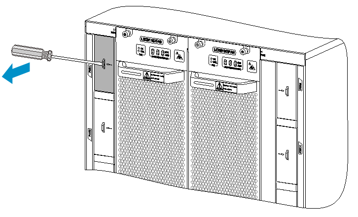
Figure3-20 Removing a filler panel (2)
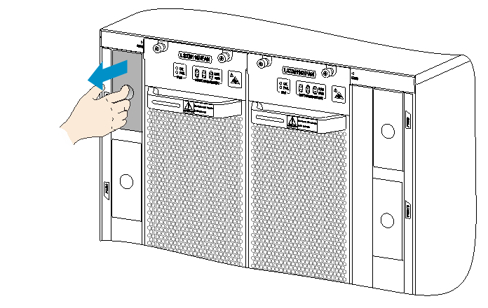
Figure3-21 Installing a power module (S12516X-AF switch)
Connecting the power cord
|
|
CAUTION: · Power on the switch after you have installed fan trays on the switch. · Make sure each power cord has a separate circuit breaker. · Turn off the circuit breaker before you connect the power cord. |
Connecting an AC power cord
|
|
CAUTION: Use AC power cords with straight connectors for an S12501X-AF switch. |
To connect an AC power cord:
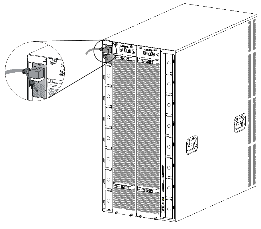
1. Connect the AC power cord connector to the AC input receptacle of the power module.
2. Use a removable cable tie or self-adhesive cable tie (provided with the power module) to secure the power cord to the handle of the power module.
3. Connect the other end of the power cord to an external AC power source.
Figure3-22 Using a removable cable tie to secure the power cord to the switch (S12516X-AF switch)
Connecting a DC power cord
To connect the DC power cord:
1. Connect the DC power cord connector to the DC input receptacle of the power module.
2. Fasten the screw on the connector to secure the connector to the receptacle.
3. Connect the other end of the power cord to an external DC power source.
Figure3-23 Connecting the DC power cord
Installing transceiver modules
|
|
CAUTION: · To prevent particles from entering the ports, keep the dust plugs in the SFP+/SFP ports if you are not to install transceiver modules or cables in the ports. · To prevent particles from entering the ports, install the dust plugs that come with the LPUs in the QSFP+/QSFP28/QSFP-DD/CXP/CFP2 ports if you are not to install transceiver modules or cables in the ports. |
Installing an SFP+/SFP/QSFP+/QSFP28/QSFP-DD transceiver module
|
|
CAUTION: · Read the following instructions before you install an SFP+/SFP/QSFP+/QSFP28/QSFP-DD transceiver module. Failure to follow these instructions might cause damage to the SFP+/SFP/QSFP+/QSFP28/QSFP-DD transceiver module. · Do not remove the dust plug from the SFP+/SFP/QSFP+/QSFP28/QSFP-DD transceiver module if you are not to connect an optical fiber to the module. · Before you install an SFP+/SFP/QSFP+/QSFP28/QSFP-DD transceiver module, remove the optical fiber (if any) from it. |
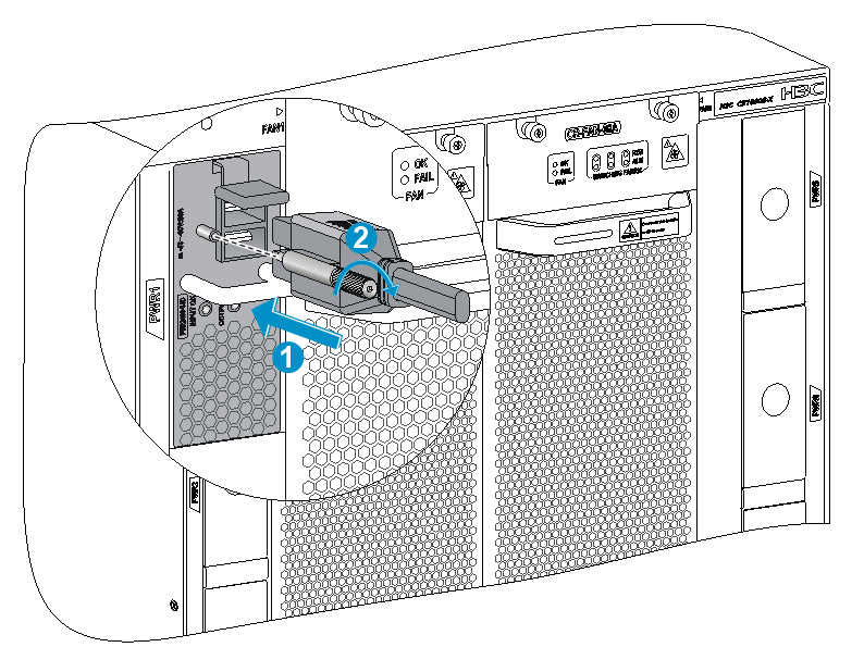
To install an SFP+/SFP/QSFP+/QSFP28/QSFP-DD transceiver module:
1. Unpack the module.
Do not touch the golden plating of the module.
2. Pivot the clasp of the module up.
For a QSFP+ module that uses a plastic pull latch, skip this step.
3. Hold the module by its two sides and align the module with the port. Gently push the module into the port until it has firm contact with the port, as shown in Figure3-26.
¡ For an SFP+ module, press the module down so you can push the module straight into the port.
¡ If you cannot hold the module by its two sides because of high module density, press the module on its head end to push it in.
Figure3-24 Installing an SFP+/SFP/QSFP+/QSFP28/QSFP-DD transceiver module (S12516X-AF switch)
For information about connecting an optical fiber, see "Connecting your switch to the network."
Installing a CFP2 transceiver module
|
|
CAUTION: · Read the following instructions before you install a CFP2 transceiver module. Failure to follow these instructions might cause damage. · Do not remove the dust plug from the CFP2 transceiver module if you are not to connect an optical fiber to the module. · Before you install or remove a CFP2 transceiver module, remove the optical fiber (if any) from it. |
To install a CFP2 transceiver module:
1. Unpack the CFP2 transceiver module.
Do not touch the golden plating of the module.
2. Pivot the module handle up.
3. Correctly orient the CFP2 transceiver module and make sure the module handle is on top of the CFP2 transceiver module. Gently push the module into the port until it clicks into place.
Figure3-25 Installing a CFP2 transceiver module (S12516X-AF switch)
|
(1) Pivot the module handle up |
(2) Gently push the module into the port |
For information about connecting an optical fiber, see "Connecting your switch to the network."
Installing a CXP transceiver module
|
|
CAUTION: · Read the following instructions before you install a CXP transceiver module. Failure to follow these instructions might cause damage to the CXP transceiver module. · Do not remove the dust plug from the CXP transceiver module if you are not to connect an optical fiber to the module. · Before you install a CXP transceiver module, remove the optical fiber (if any) from it. |
CXP transceiver modules are available in two types. One type is with a rubber pull latch and the other is with a plastic pull latch.
The installation and removal procedures are the same for the CXP transceiver modules with a rubber or plastic pull latch. This guide uses the CXP transceiver module with a plastic pull latch as an example.
To install a CXP transceiver module:
1. Unpack the CXP transceiver module.
Do not touch the golden plating of the module.
2. Correctly orient the CXP transceiver module and make sure the pull latch is on top of the CXP transceiver module. Gently push the module into the slot until it has firm contact with the slot.
Figure3-26 Installing a CXP transceiver module (S12516X-AF switch)
For information about connecting an optical fiber, see "Connecting your switch to the network."
Connecting a CXP fiber cable
|
|
CAUTION: · Read the following instructions before you connect a CXP fiber cable. Failure to follow these instructions might cause damage to the CXP fiber cable. · H3C provides only CXP AOC cables. |
CXP fiber cables are hot swappable.
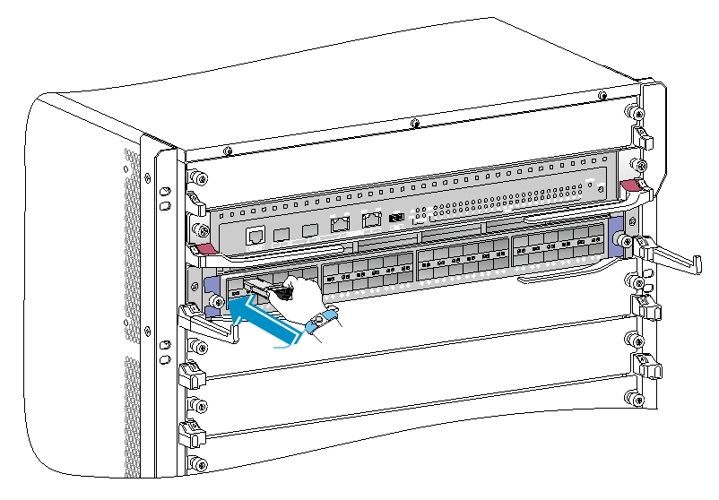
To connect a CXP fiber cable:
1. Unpack the cable.
2. Plug the cable connector into the port. Make sure the cable connector is correctly oriented.
Connecting an SFP+/QSFP+/QSFP28/QSFP-DD/QSFP+ to SFP+ copper cable
|
|
CAUTION: When you connect a fiber cable, make sure the bend radius of the cable is no less than eight times the fiber diameter. |
SFP+, QSFP+, QSFP28, QSFP-DD, and QSFP+ to SFP+ copper cables are hot swappable.
Choose cables based on ports and transmission distance:
· SFP+ copper cable—Short distance transmission between SFP+ ports.
· QSFP+ copper cable—Short distance transmission between QSFP+ ports.
· QSFP+ to SFP+ copper cable—Short distance transmission between QSFP+ and SFP+ ports.
· QSFP28 copper cable—Short distance transmission between QSFP28 ports.
· QSFP-DD copper cable—Short distance transmission between QSFP-DD ports.
To connect an SFP+ copper cable, QSFP+ copper cable, QSFP+ to SFP+ copper cable, QSFP28, or QSFP-DD copper cable:
1. Unpack the cable.
2. Plug the cable connector into the port. Make sure the cable connector is correctly oriented.
