- Table of Contents
-
- H3C S12500X-2L Switch Installation Guide-5W101
- 00-Preface
- 01-Chapter 1 Preparing for Installation
- 02-Chapter 2 Installing the Switch
- 03-Chapter 3 Installing Removalbe Components
- 04-Chapter 4 Connecting Your Switch to the Network
- 05-Chapter 5 Troubleshooting
- 06-Chapter 6 Replacement Procedures
- 07-Appendix A Chassis Views and Technical Specifications
- 08-Appendix B Removable Components and Compatibility Matrixes
- 09-Appendix C LEDs
- 10-Appendix D Cables
- Related Documents
-
| Title | Size | Download |
|---|---|---|
| 07-Appendix A Chassis Views and Technical Specifications | 648.51 KB |
Contents
1 Appendix A Chassis views and technical specifications
Module power consumption and system power consumption
1 Appendix A Chassis views and technical specifications
Unless otherwise stated, supervisor engine units (SEUs, also called MPUs) and interface modules are collectively referred to as "modules" in this document.
Chassis views
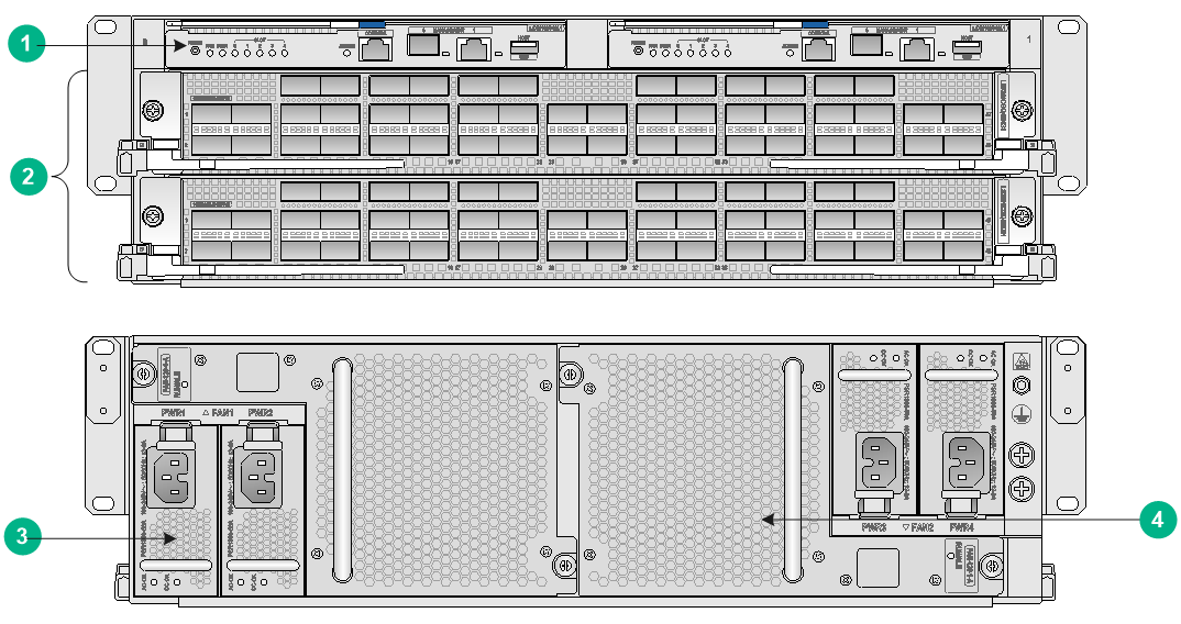
The switch has an SEU section, interface module section, power supply section, and fan tray section.
Figure1-1 Front and rear views
|
(1) SEU section |
(2) Interface module section |
|
(3) Power supply section |
(4) Fan tray section |
Table1-1 Description for the switch sections
|
Section |
Slots |
Description |
|
SEU section (The SEU slot number and SEU module identifier are highlighted in pink.) |
2 (slots 0 and 1) |
You can install one SEU, or two SEUs for redundancy for the switch. To install one SEU for the switch, you can install it in either of the SEU slots. |
|
Interface module section (The interface module edges and ejector levers and the ejector lever pillow blocks have purple marks.) |
2 (slots 2 and 3) |
You can install one or two interface modules for the switch as needed. To install one interface module for the switch, you can install it in either of the interface module slots. |
|
Power supply section |
4 (slots PWR 1 to PWR 4) |
The switch has four power supply slots, with two on each side of the chassis rear. The switch supports N+N and N+1 power redundancy. |
|
Fan tray section |
2 (slots FAN 1 and FAN 2) |
As a best practice, install two fan trays for the switch to achieve 1+1 redundancy and reduce switch noises. |
No SEUs, interface modules, fan trays, or power supplies are provided with the switch. Order them as required. For the SEUs, interface modules, fan trays, and power supplies available for the switch, see "Appendix B Removable components and compatibility matrixes."
Weights and dimensions
Table1-2 Chassis weights and dimensions
|
Model |
Weight |
Height |
Width |
Depth |
|
S12500X-2L |
< 60 kg (132.28 lb) |
133 mm (5.24 in)/3 RU |
440 mm (17.32 in) |
895 mm (35.24 in) |
|
|
NOTE: · Rack height is measured in RUs. One RU is 44.45 mm (1.75 in). · Table1-2 lists dimensions for the switch, excluding the mounting brackets, cable management brackets, modules, and power supplies. |
Table1-3 Module weights and dimensions
|
Model |
Weight |
Height |
Width |
Depth |
|
LSXM1SUP02L1 |
2.07 kg (4.56 lb) |
22.5 mm (0.89 in) |
193.0 mm (7.60 in) |
364.3 mm (14.34 in) |
|
LSXM1CGQ48KB1 |
9.25 kg (20.39 lb) |
50.0 mm (1.97 in) |
432.6 mm (17.03 in) |
519.8 mm (20.46 in) |
|
|
NOTE: Module dimensions are typically expressed in H × W × D format: · Height—Height of the front panel of the module. · Width—Width of the front panel of the module. · Depth—Depth from the front panel of the module to the connector (Including the connector, but excluding the ejector levers and captive screws). |
Table1-4 Power supply weights and dimensions
|
Model |
Weight |
Height |
Width |
Depth |
|
PSR1800-56A |
1.6 kg (3.52 lb) |
41.0 mm (1.61 in) |
82.6 mm (3.25 in) |
297.7 mm (11.72 in) |
|
PSR1800-56D |
2.0 kg (4.40 lb) |
41.0 mm (1.61 in) |
82.6 mm (3.25 in) |
297.7 mm (11.72 in) |
Table1-5 Fan tray weights and dimensions
|
Model |
Weight |
Height |
Width |
Depth |
|
FAN-120-1-A |
1.6 kg (3.52 lb) |
123.0 mm (4.84 in) |
214.0 mm (8.43 in) |
123.0 mm (4.84 in) |
Module power consumption and system power consumption
Module power consumption
The power consumption of the modules depends on the module model and state. Table1-6 shows the power consumption for different module models.
· The static power consumption of a module refers to the power consumed by the module when the module is running but all ports on the module are down and when no transceiver module is available on the fiber port of the module.
· The dynamic power consumption of a module refers to the power consumed by the module when all the ports on the module are link up and send broadcasts.
Table1-6 Module power consumption
|
Model |
Minimum static power consumption |
Maximum dynamic power consumption |
|
LSXM1SUP02L1 |
28 W |
35 W |
|
LSXM1CGQ48KB1 |
395 W |
765 W |
Fan tray power consumption
The switch uses fan trays that can automatically adjust the fan speed based on the device temperature. The power consumed by a fan tray depends on the fan speed.
Table1-7 Fan tray power consumption
|
Fan tray model |
Minimum fan tray power consumption |
Maximum fan tray power consumption |
|
FAN-120-1-A |
17 W |
269 W |
System power consumption
The system power consumption of the switch depends on the type and number of modules and the fan tray power consumption.
· The minimum system power consumption is the total static power consumption of all modules plus the minimum fan tray power consumption.
· The maximum system power consumption is the total dynamic power consumption of all modules plus the maximum fan tray power consumption.
For example, for an S12500X-2L switch that has two LSXM1SUP02L1 SEUs, two LSXM1CGQ48KB1 interface modules, and two FAN-120-1-A fan trays, the minimum system power consumption of the switch is 2 × 28 + 2 × 395 + 2 × 17 = 880 W. The maximum system power consumption of the switch is 2 × 35 + 2 × 765 + 2 × 269 = 2138 W.
Heat dissipation
Heat dissipation is measured in BTU/h, and 1 W equals 3.4121 BTU/h.
The heat dissipation of a switch depends on its power consumption. To calculate heat dissipation of the switch, assume 90% power consumption is converted to heat, and the efficiency of the power supply is 90%. Heat dissipation/hour of the switch is 0.9 × (total power consumption of the modules plus power consumption of the fan tray)/0.9 × 3.4121.
For the power consumption of the modules and fan trays of the switch, see "Module power consumption and system power consumption."
Environmental specifications
Table1-8 Environmental specifications
|
Description |
Operating |
Non-operating |
|
Temperature |
0°C to 40°C (32°F to 104°F) |
–40°C to +70°C (–40°F to +158°F) |
|
Relative humidity (noncondensing) |
5% to 95% |
5% to 95% |
Noise
The switch uses fan trays that can automatically adjust the fan speed based on the device temperature The sound pressure levels vary by fan speed. For more information, see Table1-9.
Table1-9 Sound pressure levels
|
Switch model |
Fan tray model |
Sound pressure level in the acceptable temperature range |
Sound pressure level when the fan tray operates at full speed |
|
S12500X-2L (with two fan trays) |
FAN-120-1-A |
66.7 dBA |
81.7 dBA |
|
|
NOTE: The sound pressure levels are measured according to the method specified in ISO 7779 at the bystander position. |