- Table of Contents
-
- H3C S12500X-2L Switch Installation Guide-5W101
- 00-Preface
- 01-Chapter 1 Preparing for Installation
- 02-Chapter 2 Installing the Switch
- 03-Chapter 3 Installing Removalbe Components
- 04-Chapter 4 Connecting Your Switch to the Network
- 05-Chapter 5 Troubleshooting
- 06-Chapter 6 Replacement Procedures
- 07-Appendix A Chassis Views and Technical Specifications
- 08-Appendix B Removable Components and Compatibility Matrixes
- 09-Appendix C LEDs
- 10-Appendix D Cables
- Related Documents
-
| Title | Size | Download |
|---|---|---|
| 03-Chapter 3 Installing Removalbe Components | 3.78 MB |
1 Installing removable components
Installing cable management brackets
Installing transceiver modules
Installing a QSFP+/QSFP28 transceiver module
Connecting a QSFP+/QSFP28 copper cable
1 Installing removable components
|
|
WARNING! Long-time exposure to strong air flow might cause discomfort. As a best practice, do not stand close to the air outlet vents while the switch is operating. If you must be next to the switch on the air outlet vent side for an extended period, avoid the air flow or take other protective measures. |
|
|
CAUTION: · As a best practice, connect power cords after installing all required removable components. · To ensure good ventilation, install filler panels in unused slots. |
This section describes the installation procedures for the supervisor engine units (SEUs, also called MPUs), interface modules, fan trays, and power supplies.
|
|
TIP: Keep the chassis and the component packages secure for future use. |
Attaching an ESD wrist strap
The switch is provided with an ESD wrist strap. To minimize ESD damage to electronic components, wear the ESD wrist strap and make sure it is reliably grounded before you install removable components.
To attach an ESD wrist strap:
1. Make sure the switch is reliably grounded. For information about how to ground your switch, see "Grounding the switch."
2. Put on the wrist strap.
3. Tighten the wrist strap to make sure it makes good skin contact.
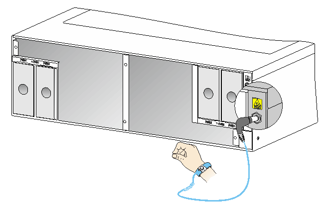
4. As shown in Figure1-1, insert the ESD wrist strap into the ESD jack on the chassis.
|
|
CAUTION: Use a multimeter to check the resistance of the ESD wrist strap. Make sure the resistance reading between your body and the ground is between 1 and 10 megohms. |
Figure1-1 Attaching an ESD wrist strap
|
(1) ESD jack (with an ESD sign) |
Installing modules
|
|
IMPORTANT: Before installing a module in the chassis, make sure the connectors on the module are not broken or blocked. |
Unless otherwise stated, SEUs and interfaces modules are collectively referred to as "modules" in this document. The modules are hot swappable.
For the SEUs and interface modules available for the switch, see "Appendix B Removable components and compatibility matrixes."
Installing SEUs
|
|
CAUTION: · If you are not to install an SEU in an SEU slot, keep the filler panel in the slot. · When you install an SEU, avoid damaging the connectors on the SEU. · To prevent a filler panel from being drawn into the chassis when fan speed is high, use both hands to grasp the filler panel by its two sides during filler panel installation and removal on an operating switch. |
You can install one SEU, or two SEUs for redundancy on the switch. If you are to install one SEU, install it in either of the SEU slots. The module identifier on an SEU is highlighted in pink.
To install an SEU:
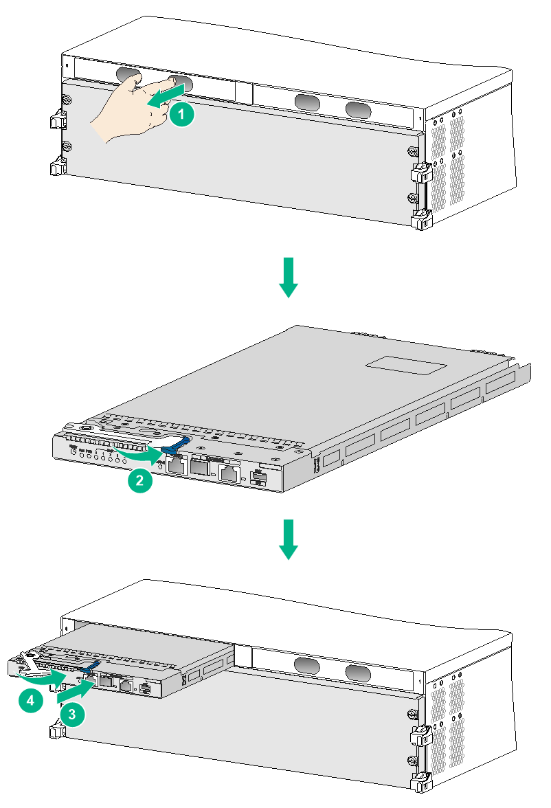
1. As shown by callout 1 in Figure1-2, remove the filler panel from the target SEU slot.
Keep the removed filler panel secure for future use.
2. As shown by callout 2 in Figure1-2, press the latch on the SEU to release the ejector lever. Fully open the ejector lever.
3. As shown by callout 3 in Figure1-2, correctly orient the SEU. Hold the SEU by the front panel with one hand and support the bottom with the other. Push the SEU steadily into the slot along the guide rails until it has firm contact with the slot.
Keep the SEU parallel to the slot to avoid touching other components in the chassis.
4. As shown by callout 4 in Figure1-2, close the ejector lever until the latch locks the ejector lever in place.
Installing interface modules
Removing the protective blank panel
The switch comes with a protective blank panel installed over the interface module slots to protect the switch from damage during shipment.
To remove the protective blank panel:
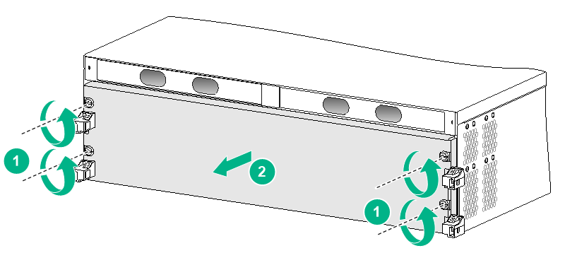
1. As shown by callout 1 in Figure1-3, use a Phillips screwdriver to remove the screws that secure the protective blank panel to the switch.
Keep the removed screws secure for future use.
2. As shown by callout 2 in Figure1-3, remove the protective blank panel.
|
|
CAUTION: The protective blank panel is heavy. To avoid bodily injury, use both hands to remove it. |
Keep the removed protective blank panel secure for future use.
Figure1-3 Removing the protective blank panel
Installing an interface module
The ejector levers of the interface modules and the ejector lever pillow blocks have purple marks.
To install an interface module:
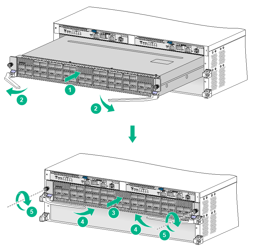
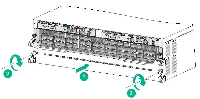
1. As shown by callout 1 in Figure1-4, orient the interface module with the lettering on it upward. Holding the interface module by the front panel with one hand and supporting its bottom with the other, slide the interface module steadily into the target slot along the guide rails.
Keep the interface module parallel to the slot to avoid touching other components in the chassis.
2. As shown by callout 2 in Figure1-4, fully open the ejector levers when most of the interface module is inserted into the slot.
3. Push the interface module until the brakes on the ejector levers touch the slot edges tightly.
4. As shown by callout 3 in Figure1-4, continue to push the interface module by its middle part on the front panel until you cannot move it.
5. As shown by callout 4 in Figure1-4, push the ejector levers inward until they come in close contact with the panel.
6. As shown by callout 5 in Figure1-4, fasten the captive screws to secure the interface module to the chassis.
As a best practice, use a torque of 5 kgf-cm (0.49 Nm) to fasten the captive screws.
Figure1-4 Installing an interface module
Installing a filler panel in an empty interface module slot
|
|
CAUTION: · If you are not to install an interface module in an interface module slot, keep the filler panel in the slot. · To prevent a filler panel from being drawn into the chassis when fan speed is high, use both hands to grasp the filler panel by its two sides during filler panel installation and removal on an operating switch. |
To install a filler panel in an empty interface module slot:
1. As shown by callout 1 in Figure1-5, align and insert the filler panel into the empty interface module slot.
2. As shown by callout 2 in Figure1-5, fasten the captive screws on the filler panel.
As a best practice, use a torque of 5 kgf-cm (0.49 Nm) to fasten the captive screws.
Figure1-5 Installing the filler panel in an empty interface module slot
Installing cable management brackets
|
|
CAUTION: To avoid device damage, press the spring tab when you remove a cable management bracket. |
The cable management brackets are installed on the two sides of the interface module slots. As a best practice, install cable management brackets after you have installed interface modules.
As shown in Figure1-6, insert the cable management bracket end that has a spring tab into the cable management bracket hole until the bracket has close contact with the hole.
Figure1-6 Installing a cable management bracket
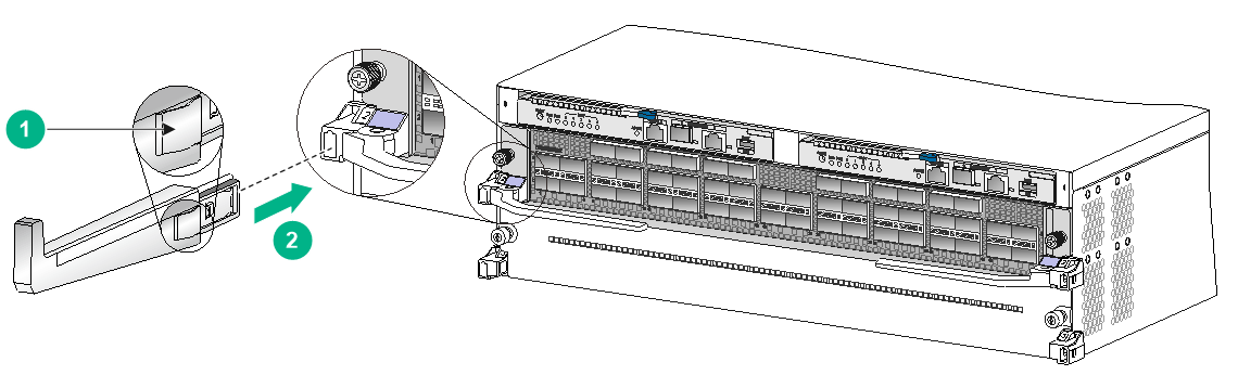
|
(1) Spring tab on the cable management bracket |
|
(2) Align the cable management bracket with the bracket hole |
Installing fan trays
Restrictions and guidelines
Follow these restrictions and guidelines for installing fan trays on the switch:
· The switch has two fan tray slots: FAN1 and FAN2. Install two fan trays on the switch.
· To prevent dust from entering the chassis, keep the fan trays in position when the switch is not in use.
· The fan tray is hot swappable. Follow these guidelines when you hot swap a fan tray:
¡ Ensure electricity safety.
¡ Replace a fan tray only when the other fan tray is operating correctly.
¡ To prevent dust from entering the chassis, keep the failed fan tray in position before the replacement.
· To install a fan tray in slot FAN1, orient the fan tray with the LED on the left side of the front panel. To install a fan tray in slot FAN2, orient the fan tray with the LED on the right side of the front panel.
· To avoid damaging the fan tray, use both hands when installing or removing a fan tray.
· When you hot swap a fan tray, only one fan tray is operating and it automatically increases the fan rotation speed and makes louder noise. Take protection measures such as wearing an earmuff or earplug. In addition, make good preparation before the hot swapping to minimize the operation time.
Procedure
1. Unpack the fan tray.
2. Orient the fan tray correctly. Align the fan tray with the fan tray slot.
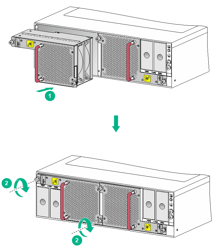
3. Holding the fan tray handle with one hand and supporting the bottom of the fan tray with the other, insert the fan tray part way into the slot, as shown by callout 1 in Figure1-7.
Keep the fan tray as steady as possible while inserting it into the slot.
4. Squeezing the captive screw with one hand and holding the fan tray handle with the other, push the fan tray fully into the slot.
5. Fasten the captive screws on the fan tray.
As a best practice, use a torque of 5 kgf-cm (0.49 Nm) to fasten the captive screws.
Figure1-7 Installing a fan tray
Installing power supplies
|
|
CAUTION: The switch comes with a filler panel in each power supply slot. If you are not to install a power supply in a slot, keep the filler panel in the slot. |
The installation procedure is the same for AC and DC power supplies. The following procedures install an AC power supply.
To install an AC power supply:
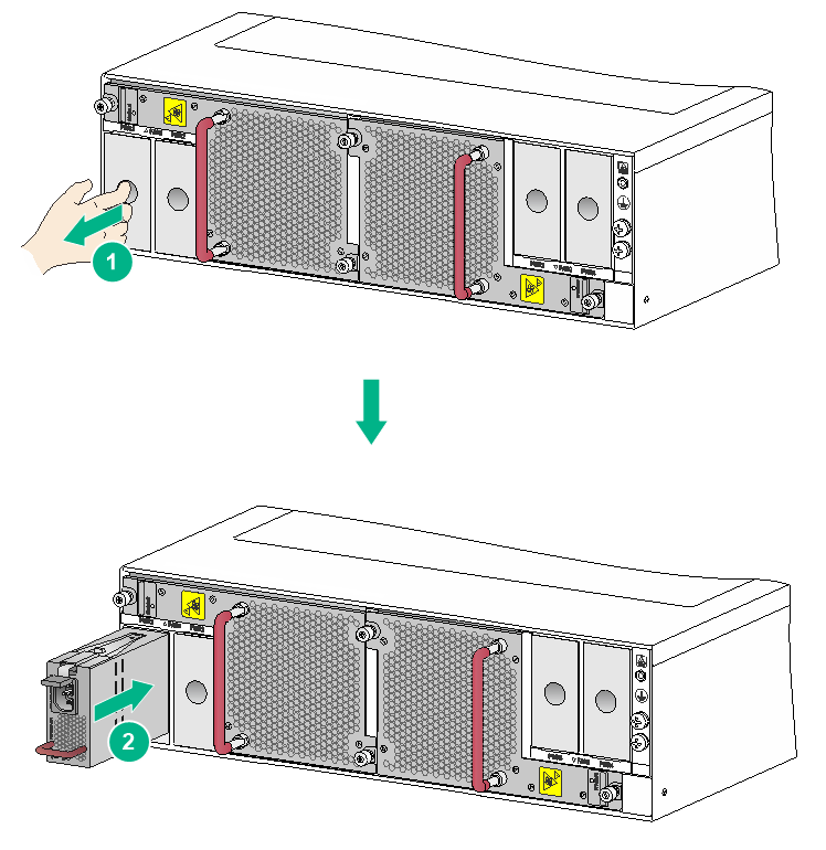
1. Put your forefinger into the hole of the filler panel and pull out the filler panel along the guide rails. See callout 1 in Figure1-8.
2. As shown in callout 2 in Figure1-8, correctly orient the power supply.
If you install the power supply in a left power supply slot, make sure the latch is above the handle. If you install the power supply in a right power supply slot, make sure the latch is below the handle.
3. Holding the power supply handle with one hand and supporting the power supply bottom with the other, slide the power supply along the guide rails into the slot until the latch locks the power supply in place.
Figure1-8 Installing a power supply
Connecting the power cord
|
|
CAUTION: · Power on the switch after you have installed fan trays on the switch. · Make sure each power cord has a separate circuit breaker. · Turn off the circuit breaker before you connect the power cord. |
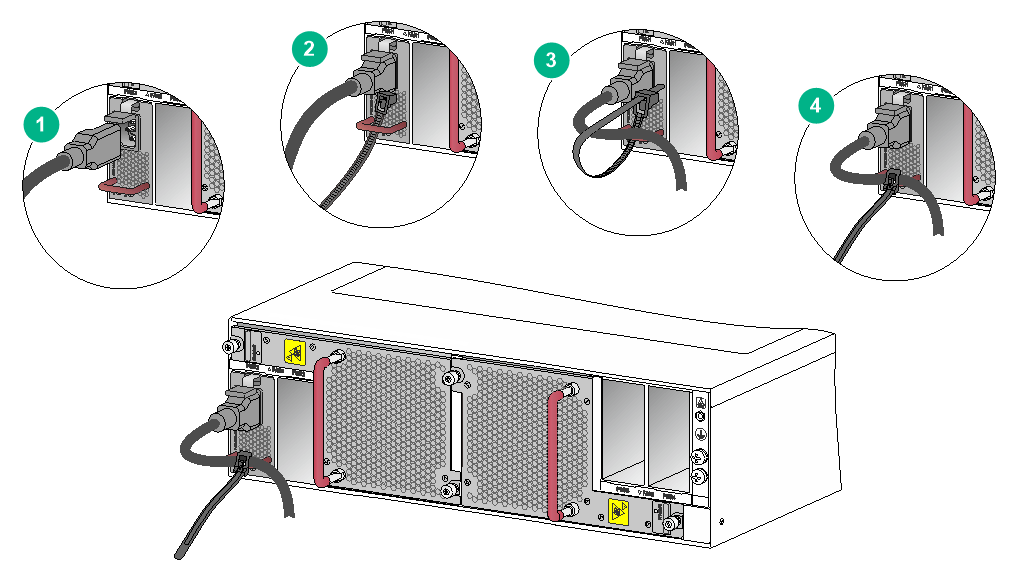
Connecting an AC power cord
1. Connect the female connector of the AC power cord to the AC input receptacle of the power supply.
2. Use a releasable cable tie to secure the power cord to the handle of the power supply.
3. Connect the other end of the power cord to an AC power source.
Figure1-9 Connect an AC power cord
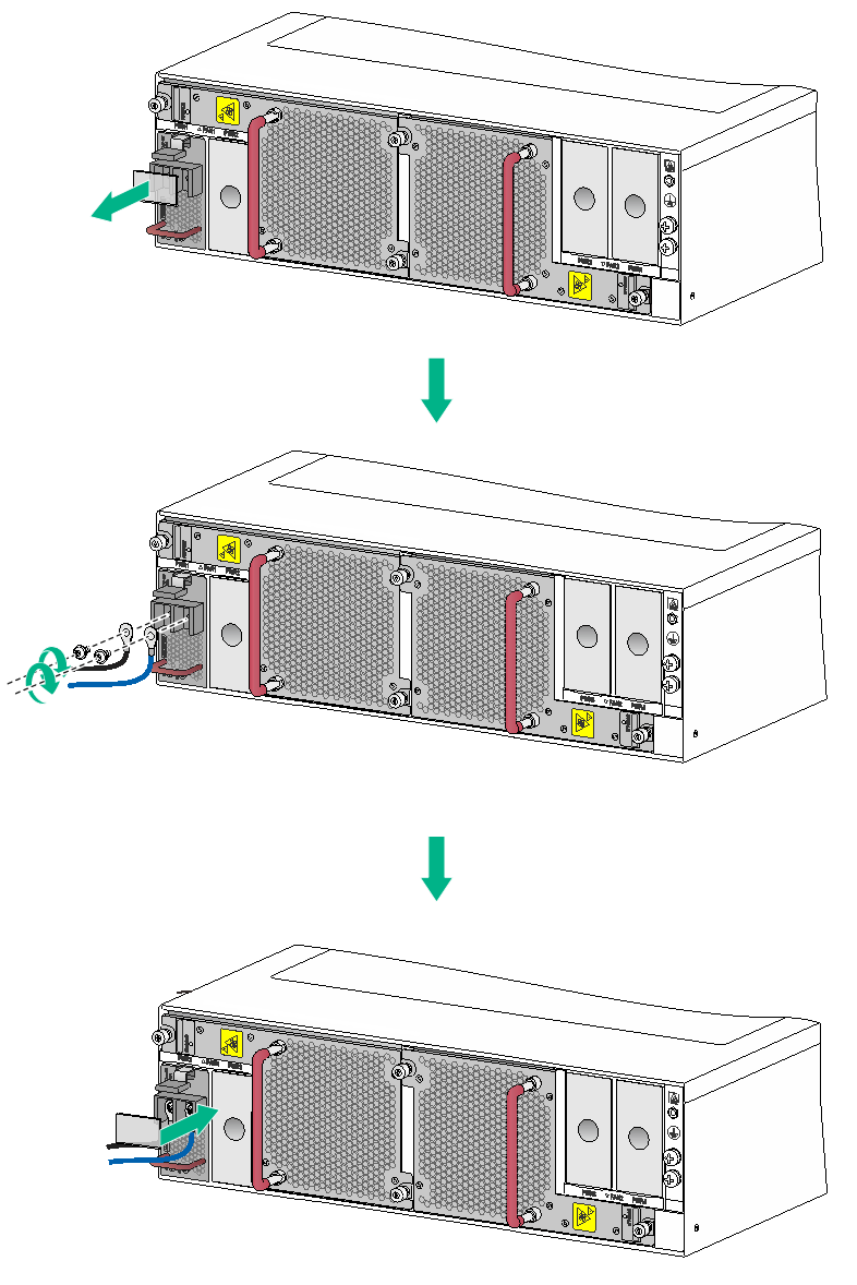
Connecting a DC power cord
|
|
WARNING! · Before connecting the DC power cord, make sure the circuit breakers for both the positive lead (+) and the negative lead (–) are turned off. · To avoid electrical shock, a plastic cover is installed over the wiring terminals. Remove the cover when you connect the DC power cord and install the cover in time after you connect the DC power cord. |
To connect the DC power cord:
1. Remove the plastic cover over the wiring terminals, and use a Phillips screwdriver to remove the M5 screws.
2. Connect the wire marked with the negative polarity symbol (–) to the negative terminal (–) and the wire marked with the positive polarity symbol (+) to the positive terminal (+).
3. Fasten the M5 screws to secure the wires and then install the plastic cover.
As a best practice, use a torque of 20 kgf-cm (1.96 Nm) to fasten the M5 screws.
4. Connect the other end of the power cord to a DC power source.
Figure1-10 Connecting a DC power cord
Installing transceiver modules
|
|
CAUTION: To prevent particles from entering the QSFP+/QSFP28 ports, install the dust plugs that come with the interface modules in the ports if you are not to install transceiver modules or cables in the ports. |
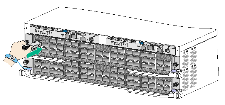
Installing a QSFP+/QSFP28 transceiver module
|
|
CAUTION: · Read the following instructions before you install an QSFP+/QSFP28 transceiver module. Failure to follow these instructions might cause damage to the module. · Do not remove the dust plug from the QSFP+/QSFP28 transceiver module if you are not to connect an optical fiber to the module. For more information about connecting an optical fiber, see "Connecting the switch to the network through an optical fiber." · Before you install an QSFP+/QSFP28 transceiver module, remove the optical fiber (if any) from it. |
To install a QSFP+/QSFP28 transceiver module:
1. Wear an ESD wrist strap and make sure the strap makes good skin contact and is reliably grounded. For more information, see "Attaching an ESD wrist strap."
2. Unpack the module.
Do not touch the golden plating of the module.
3. Pivot the clasp of the module up. Skip this step for a transceiver module that uses a plastic pull latch.
4. Holding the module by its two sides, gently push the module into the slot until it has firm contact with the slot, as shown in Figure1-11.
If you cannot hold the module by its two sides because of high module density, press the module on its head end to push it in.
Figure1-11 Installing a QSFP+/QSFP28 transceiver module
Connecting a QSFP+/QSFP28 copper cable
|
|
CAUTION: When you connect a copper cable, make sure the bend radius of the cable is not less than eight times the fiber diameter. |
The copper cables are hot swappable.
You can use QSFP+ copper cables to connect QSFP+ ports and QSFP28 copper cables to connect QSFP28 ports over a short distance.
To connect a QSFP+/QSFP28 copper cable:
1. Wear an ESD wrist strap and make sure the strap makes good skin contact and is reliably grounded. For more information, see "Attaching an ESD wrist strap."
2. Unpack the copper cable.
3. Correctly orient the connector of the cable and insert the connector into the port.