- Table of Contents
-
- H3C S12500X-2L Switch Installation Guide-5W101
- 00-Preface
- 01-Chapter 1 Preparing for Installation
- 02-Chapter 2 Installing the Switch
- 03-Chapter 3 Installing Removalbe Components
- 04-Chapter 4 Connecting Your Switch to the Network
- 05-Chapter 5 Troubleshooting
- 06-Chapter 6 Replacement Procedures
- 07-Appendix A Chassis Views and Technical Specifications
- 08-Appendix B Removable Components and Compatibility Matrixes
- 09-Appendix C LEDs
- 10-Appendix D Cables
- Related Documents
-
| Title | Size | Download |
|---|---|---|
| 02-Chapter 2 Installing the Switch | 802.12 KB |
Confirming installation preparations
Installing the switch in a rack
Switch dimensions and rack requirements
Attaching slide rails to the rack
Installing cage nuts for attaching mounting brackets
1 Installing the switch
|
|
IMPORTANT: Keep the packages of the switch and the components for future use. |
Confirming installation preparations
Before you install the switch, verify that:
· You have read "Preparing for installation" carefully and the installation site meets all the requirements.
· A 19-inch rack is ready for use and the rack has enough space to accommodate the switch.
For information about how to install a rack, see the rack installation guide.
· The rack is sturdy and reliably grounded.
· No debris exists inside or around the rack.
· The rack can provide power as required by the switch. For information about the system power consumption, see "Module power consumption and system power consumption." For power supply specifications such as power input mode and rated input voltage, see "Power supplies."
· The total height of the switches to be installed is not higher than the available installation height of the rack and enough clearance is reserved for cable routing.
· The switch is ready for installation and has been carried to a place near the rack and convenient for moving.
Installing the switch in a rack
Switch dimensions and rack requirements
To mount the switch in an enclosed rack, make sure the rack meets the requirements described in Table1-1.
|
Switch dimensions |
Rack requirements |
|
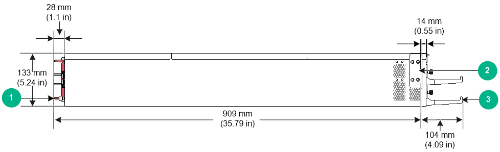
· Height—133 mm (5.24 in) (3 RU). · Width—440 mm (17.32 in). · Chassis depth—895 mm (35.24 in) · Total depth—1013 mm (39.88 in) ¡ 104 mm (4.09 in) from the rack-facing surface of the mounting brackets to the front ends of the cable management brackets ¡ 909 mm (35.79 in) from the rack-facing surface of the mounting brackets to the power supply handles at the chassis rear |
· A minimum of 1.1 m (3.61 ft) in depth (recommended) · A minimum of 130 mm (5.12 in) from the front rack post to the front door · A minimum of 950 mm (37.40 in) from the front rack post to the rear door |
|
|
NOTE: As a best practice, use a rack that has a single door at the front. |
Figure1-1 Switch dimensions
|
(1) Power supply handle |
(2) Mounting bracket |
|
(3) Cable management bracket |
|
Attaching slide rails to the rack
To rack-mount the switch, select and attach slide rails to the rack. Make sure the slide rails can support the maximum weight of the switch. See Table1-2 for the maximum chassis weight and applicable slide rails.
Table1-2 Maximum chassis weight and applicable slide rails
|
Max. chassis weight (fully configured) |
Applicable slide rails |
|
|
Slide rail model |
Adjustment range |
|
|
70 kg (154.32 lb) |
LSVM1BSR10 |
630 mm to 900 mm (24.80 in to 35.43 in) |
The LSVM1BSR10 slide rails have the load-bearing flanges at its bottom and do not occupy rack space after switch installation. As a best practice, use the provided LSVM1BSR10 slide rails for the switch.
To attach slide rails to the rack:
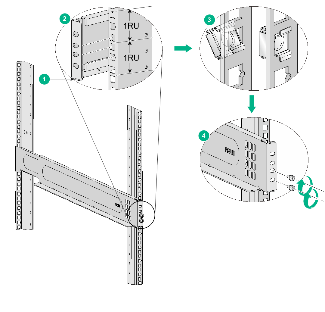
1. Read the signs on the slide rails to identify the front and rear ends of the slide rails.
2. Identify the 2RU space on the rack posts for installing the slide rails.
3. As shown by callout 1 in Figure1-2, insert the locating pins at the bottom of the slide rails into the lowest square holes within the 2U space on the rack posts and align the four installation holes in the slide rails with four square holes on the rack posts.
4. As shown by callout 2 in Figure1-2, mark cage nut installation holes on the rack posts. Make sure the marked square holes are at the same height on the rack posts.
¡ On the front rack posts, mark the bottom three square holes aligned with the installation holes on the slide rails. The top aligned square hole will be blocked by the mounting bracket.
¡ On the rear rack posts, mark the four square holes aligned with the installation holes on the slide rails.
5. As shown by callout 3 in Figure1-2, install cage nuts into the marked square holes on each rack post.
6. As shown by callout 4 in Figure1-2, use M6 screws with a recommended torque of 30 kgf-cm (2.94 Nm) to attach the slide rails to the rack posts.
On the front rack posts, use the bottom two cage nuts for attaching the slide rails. The top cage nut will be used for securing the mounting bracket.
7. Ensure that the load-bearing plane of the slide rails is perpendicular to the four rack posts.
Figure1-2 Installing slide rails
Installing cage nuts for attaching mounting brackets
Before mounting the chassis in the rack, install cage nuts on the front rack posts for attaching the mounting brackets:
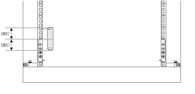
1. As shown in Figure1-3, determine and mark the cage nut installation holes on the front rack posts.
2. Install cage nuts in the marked square holes on the front rack posts. If the square holes have screws installed, remove them.
Figure1-3 Installing cage nuts
Mounting the switch in a rack
|
|
WARNING! · Hold the chassis handles to move the switch. Do not hold the handle of a fan tray, a power supply, or a module to move the switch. Any attempt to carry the switch with these parts might cause equipment damage or even bodily injury. · After you place the switch on the slide rails, do not leave go of your hands immediately because this might tip the switch, damaging the switch or even causing bodily injury. |
|
|
CAUTION: · The switch is heavy. As a best practice, use a mechanical lift, such as forklift truck, to move and carry the switch to the rack. · Do not place your hand into any slot when you move the chassis. · Remove the fan trays, power supplies, and filler panels from the switch before lifting. Reinstall these components after installing the switch in the rack. |
To mount the switch in the rack:
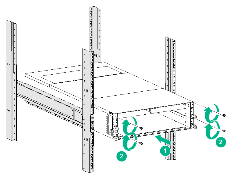
1. Face the rear of the chassis towards the front of the rack.
2. Place the switch on the slide rails from the front of the rack and slide the switch into the rack along the guide rails until the mounting brackets on the switch touch the front rack posts tightly, as shown by callout 1 in Figure1-4.
3. Use the M6 screws provided with the switch to attach the mounting brackets to the rack posts.
As a best practice, use a torque of 30 kgf-cm (2.94 Nm) to fasten the M6 screws.
If the mounting holes in the mounting brackets cannot align with the cage nuts on the rack, verify the following items:
¡ The bottom edge of the slide rail aligns with the middle of the narrower metal area between holes.
¡ The cage nuts are installed in the correct holes.
Figure1-4 Mounting the switch in the rack
|
(1) Slide the chassis into the rack |
|
(2) Use the provided M6 screws to secure the mounting brackets to the rack |
Grounding the switch
|
|
CAUTION: · Grounding the switch reliably is crucial to lightning protection and EMI protection. Ground the switch reliably before you use it. · To guarantee the grounding effect, use the yellow-green grounding cable provided with the switch to ground the switch. · Connect the grounding cable to the earthing system in the equipment room. Do not connect it to a fire main or lightning rod. |
A grounding strip is required to ground the switch. You can ground the switch by connecting the grounding cable to a grounding strip in the equipment room or the grounding strip on the rack.
To ground the switch by using a grounding strip:
1. Unpack the grounding cable.
The grounding cable provided with the switch is compliant with the NEBS standards. The two-hole grounding lug of the grounding cable is used for connecting the chassis. The ring terminal of the grounding cable is used for connecting the grounding strip.
2. Remove the grounding screws from the grounding holes at the rear of the chassis.
A grounding sign is provided with the grounding holes, as shown by callout 1 in Figure1-5.
3. Use grounding screws to attach the two-hole grounding lug of the grounding cable to the chassis.
As a best practice, use a torque of 30 kgf-cm (2.94 Nm) to fasten the grounding screws.
4. Connect the other end of the grounding cable to a grounding point or grounding strip.
Figure1-5 Connecting the grounding cable to a grounding strip
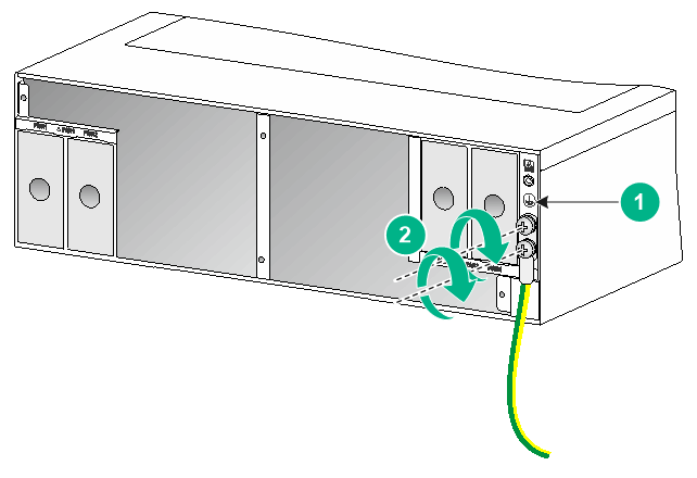
|
(1) Grounding sign |
(2) Use grounding screws to attach the two-hole grounding lug to the grounding point |