- Table of Contents
-
- H3C S6800 & S6860 & S6861 Switches Configuration Examples-Release 27xx-6W100
- 01-Login Management Configuration Examples
- 02-RBAC Configuration Examples
- 03-Software Upgrade Examples
- 04-ISSU Configuration Examples
- 05-Software Patching Examples
- 06-Ethernet Link Aggregation Configuration Examples
- 07-Port Isolation Configuration Examples
- 08-Spanning Tree Configuration Examples
- 09-VLAN Configuration Examples
- 10-VLAN Tagging Configuration Examples
- 11-PBB Configuration Examples
- 12-DHCP Snooping Configuration Examples
- 13-Cross-Subnet Dynamic IP Address Allocation Configuration Examples
- 14-IPv6 over IPv4 Manual Tunneling with OSPFv3 Configuration Examples
- 15-ISATAP Tunnel and 6to4 Tunnel Configuration Examples
- 16-IPv6 over IPv4 GRE Tunnel Configuration Examples
- 17-GRE with OSPF Configuration Examples
- 18-OSPF Configuration Examples
- 19-IS-IS Configuration Examples
- 20-BGP Configuration Examples
- 21-Policy-Based Routing Configuration Examples
- 22-OSPFv3 Configuration Examples
- 23-IPv6 IS-IS Configuration Examples
- 24-Routing Policy Configuration Examples
- 25-IGMP Snooping Configuration Examples
- 26-IGMP Configuration Examples
- 27-BIDIR-PIM Configuration Examples
- 28-Multicast VPN Configuration Examples
- 29-MLD Snooping Configuration Examples
- 30-IPv6 Multicast VLAN Configuration Examples
- 31-Basic MPLS Configuration Examples
- 32-MPLS L3VPN Configuration Examples
- 33-ACL Configuration Examples
- 34-Control Plane-Based QoS Policy Configuration Examples
- 35-Traffic Policing Configuration Examples
- 36-GTS and Rate Limiting Configuration Examples
- 37-Priority Mapping and Queue Scheduling Configuration Examples
- 38-Traffic Filtering Configuration Examples
- 39-AAA Configuration Examples
- 40-Port Security Configuration Examples
- 41-Portal Configuration Examples
- 42-SSH Configuration Examples
- 43-IP Source Guard Configuration Examples
- 44-Ethernet OAM Configuration Examples
- 45-CFD Configuration Examples
- 46-DLDP Configuration Examples
- 47-VRRP Configuration Examples
- 48-BFD Configuration Examples
- 49-NTP Configuration Examples
- 50-SNMP Configuration Examples
- 51-NQA Configuration Examples
- 52-Mirroring Configuration Examples
- 53-sFlow Configuration Examples
- 54-FCoE Configuration Examples
- 55-SPBM Configuration Examples
- 56-OpenFlow Configuration Examples
- 57-MAC Address Table Configuration Examples
- 58-Static Multicast MAC Address Entry Configuration Examples
- 59-IP Unnumbered Configuration Examples
- 60-MVRP Configuration Examples
- 61-MCE Configuration Examples
- 62-Congestion Avoidance and Queue Scheduling Configuration Examples
- 63-Attack Protection Configuration Examples
- 64-Smart Link Configuration Examples
- 65-RRPP Configuration Examples
- 66-BGP Route Selection Configuration Examples
- 67-IS-IS Route Summarization Configuration Examples
- 68-IRF Configuration Examples
- 69-MPLS OAM Configuration Examples
- 70-MPLS TE Configuration Examples
- 71-GRE with VPN Configuration Examples
- 72-VXLAN Configuration Examples
- 73-DRNI Configuration Examples
- 74-IRF 3.1 Configuration Examples
- 75-DRNI and EVPN Configuration Examples
- 76-EVPN-DCI over an MPLS L3VPN Network Configuration Examples
- 77-VCF Fabric Configuration Examples
- 78-PTP Configuration Examples
- 79-S-MLAG Configuration Examples
- 80-MPLS SR Configuration Examples
- 81-Puppet Configuration Examples
- Related Documents
-
| Title | Size | Download |
|---|---|---|
| 41-Portal Configuration Examples | 356.96 KB |
|
|
|
H3C S6800 & S6860 & S6861 Switches |
|
Portal Configuration Examples |
|
|
Copyright © 2019 New H3C Technologies Co., Ltd. All rights reserved.
No part of this manual may be reproduced or transmitted in any form or by any means without prior written consent of New H3C Technologies Co., Ltd.
Except for the trademarks of New H3C Technologies Co., Ltd., any trademarks that may be mentioned in this document are the property of their respective owners.
The information in this document is subject to change without notice.
Contents
Configuration restrictions and guidelines
Example: Configuring cross-subnet portal authentication
Applicable hardware and software versions
Configuring the RADIUS and portal server
Example: Configuring extended cross-subnet portal authentication
Applicable hardware and software versions
Configuring the RADIUS, portal, and security policy server
Example: Configuring direct portal authentication
Applicable hardware and software versions
Configuring the RADIUS and portal server
Introduction
This document provides examples for configuring the following portal authentications:
· Cross-subnet authentication—Applies to networks where Layer 3 forwarding devices exist between the authentication client and the access device. After a user passes authentication on an interface, the access device generates an ACL for the user based on the user's IP address to permit packets from the user on the interface.
· Direct authentication—Applies to networks where no layer 3 forwarding devices exist between the authentication client and the access device. In such a network, the access device can learn MAC addresses of users. The access device can use both ACLs and MAC addresses to enhance control on user packet forwarding.
Prerequisites
The configuration examples in this document were created and verified in a lab environment, and all the devices were started with the factory default configuration. When you are working on a live network, make sure you understand the potential impact of every command on your network.
This document assumes that you have basic knowledge of portal.
Configuration restrictions and guidelines
When you configure direct or cross-subnet portal authentication, follow these restrictions and guidelines:
· Only the RADIUS server can perform authentication, authorization, and accounting for portal users.
· On the RADIUS server, configure routes to reach the authentication interfaces and user networks.
· The IMC server uses session control packets to send disconnection requests to the access device. If you use the IMC server as the RADIUS server, execute the radius session-control enable command on the access device. Otherwise, the access device cannot receive portal user logout requests from the RADIUS server.
· When the access device runs Portal 2.0, configure the BAS-IP attribute for portal packets sent to the portal authentication server. Make sure the BAS-IP is the same as the IP Address configured on the portal authentication server. Otherwise, the portal authentication server will drop unsolicited portal packets (such as logout notifications) from the access device.
Example: Configuring cross-subnet portal authentication
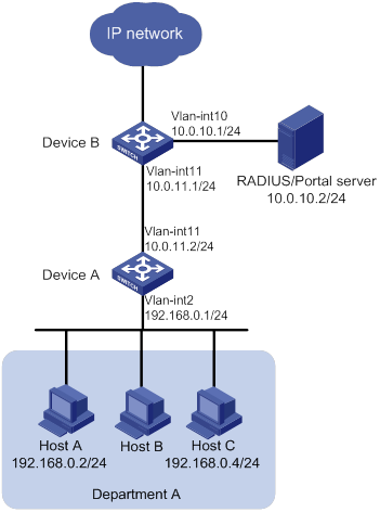
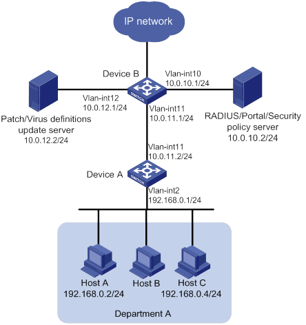
Network configuration
As shown in Figure 1, Device B supports portal authentication. An IMC server acts as a portal authentication server, a portal Web server, and a RADIUS server. The RADIUS server is used to perform AAA on portal users. In this example, the IMC server runs IMC PLAT 7.0 (E0202) and IMC UAM 7.0 (E0202).
Configure cross-subnet portal authentication. Before passing authentication, a host can access only the portal server. After passing authentication, the host can access resources in the IP network.
Analysis
To enable Device B to perform cross-subnet portal authentication through RADIUS, you must complete the following tasks:
· Configure the portal authentication and Web server, and enable cross-subnet portal authentication.
· Configure the RADIUS scheme. Specify the AAA server for the scheme and apply the scheme to the portal authentication domain.
Applicable hardware and software versions
The following matrix shows the hardware and software versions to which this configuration example is applicable:
|
Hardware |
Software version |
|
S6800 switch series S6860 switch series S6861 switch series |
Release 2702 |
Procedures
Configuring Device A
# Configure VLAN-interface 2 and VLAN-interface 11, and assign them IP addresses.
<DeviceA> system-view
[DeviceA] vlan 2
[DeviceA-vlan2] quit
[DeviceA] vlan 11
[DeviceA-vlan11] quit
[DeviceA] interface vlan-interface 2
[DeviceA-Vlan-interface2] ip address 192.168.0.1 24
[DeviceA-Vlan-interface2] quit
[DeviceA] interface vlan-interface 11
[DeviceA-Vlan-interface11] ip address 10.0.11.2 24
[DeviceA-Vlan-interface11] quit
# Assign the corresponding physical interfaces to the VLANs. (Details not shown.)
# Configure a static route to the RADIUS server.
[DeviceA] ip route-static 10.0.10.0 255.255.255.0 10.0.11.1
Configuring Device B
# Configure VLAN-interface 10 and VLAN-interface 11, and assign them IP addresses.
<DeviceB> system-view
[DeviceB] vlan 10
[DeviceB-vlan10] quit
[DeviceB] vlan 11
[DeviceB-vlan11] quit
[DeviceB] interface vlan-interface 11
[DeviceB-Vlan-interface11] ip address 10.0.11.1 24
[DeviceB-Vlan-interface11] quit
[DeviceB] interface vlan-interface 10
[DeviceB-Vlan-interface10] ip address 10.0.10.1 24
[DeviceB-Vlan-interface10] quit
# Configure portal authentication server newpt.
[DeviceB] portal server newpt
[DeviceB-portal-server-newpt] ip 10.0.10.2 key simple portal
[DeviceB-portal-server-newpt] port 50100
[DeviceB-portal-server-newpt] quit
# Configure portal Web server newpt. The URL must be the same as the URL configured for the portal page on the portal Web server.
[DeviceB] portal web-server newpt
[DeviceB-portal-websvr-newpt] url http://10.0.10.2:8080/portal
[DeviceB-portal-websvr-newpt] quit
# Enable cross-subnet authentication on VLAN-interface 11, the interface connected to Device A.
[DeviceB] interface Vlan-interface 11
[DeviceB-Vlan-interface11] portal enable method layer3
# Configure the BAS-IP as 10.0.11.1 for portal packets sent from VLAN-interface 11 to the portal authentication server.
[DeviceB-Vlan-interface11] portal bas-ip 10.0.11.1
# Specify portal Web server newpt on VLAN-interface 11.
[DeviceB-Vlan-interface11] portal apply web-server newpt
[DeviceB-Vlan-interface11] quit
# Create a RADIUS scheme named imc and enter its view.
[DeviceB] radius scheme imc
# Specify the primary authentication and accounting server, and configure the keys for communication with the server.
[DeviceB-radius-imc] primary authentication 10.0.10.2
[DeviceB-radius-imc] primary accounting 10.0.10.2
[DeviceB-radius-imc] key authentication simple expert
[DeviceB-radius-imc] key accounting simple expert
# Exclude the ISP domain name from the username sent to the RADIUS server.
[DeviceB-radius-imc] user-name-format without-domain
[DeviceB-radius-imc] quit
# Enable the RADIUS session-control feature.
[DeviceB] radius session-control enable
# Create an ISP domain named portal.com and enter its view.
[DeviceB] domain portal.com
# Configure AAA methods for the ISP domain.
[DeviceB-isp-portal.com] authentication portal radius-scheme imc
[DeviceB-isp-portal.com] authorization portal radius-scheme imc
[DeviceB-isp-portal.com] accounting portal radius-scheme imc
[DeviceB-isp-portal.com] quit
# Specify domain portal.com as the default ISP domain. If a user enters the username without the ISP domain name at login, the AAA methods of the default domain are used for the user.
[DeviceB] domain default enable portal.com
# Configure a static route to Department A.
[DeviceB] ip route-static 192.168.0.0 255.255.255.0 10.0.11.2
Configuring the RADIUS and portal server
Adding an access device
1. Log in to IMC, and click the User tab.
2. From the navigation tree, select User Access Manager > Access Device Management > Access Device.
3. Click Add.
The Add Access Device page appears.
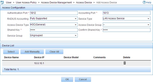
4. In the Access Configuration area, configure the following parameters:
¡ Enter expert in the Shared Key and Confirm Shared Key fields.
¡ Enter 1812 in the Authentication Port field and 1813 in the Accounting Port field.
¡ Select LAN Access Service from the Service Type list.
¡ Select H3C(General) from the Access Device Type list.
5. In the Device List area, click Add Manually.
6. On the page that appears, enter IP address 10.0.10.1 in the Start IP field, and click OK.
7. Click OK.
Figure 2 Adding an access device
Adding an access policy
1. Click the User tab.
2. From the navigation tree, select User Access Manager > Access Policy.
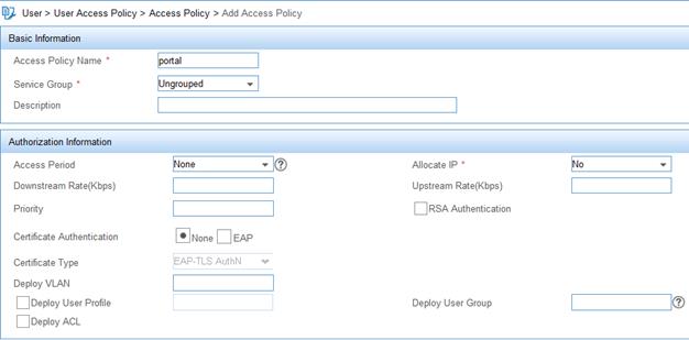
3. Click Add.
4. On the page that appears, enter portal in the Access Policy Name field.
5. Use the default settings for other parameters.
6. Click OK.
Figure 3 Adding an access policy
Adding an access service
1. Click the User tab.
2. From the navigation tree, select User Access Manager > Access Service.
3. Click Add.
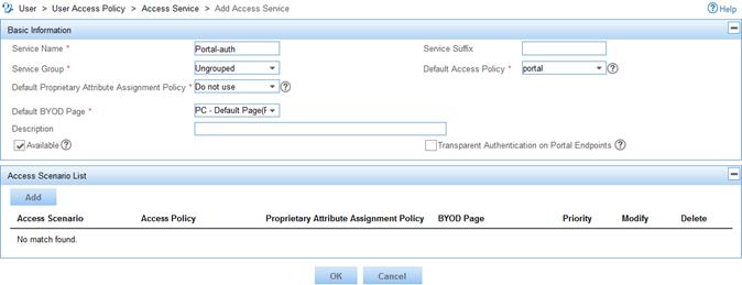
4. On the page that appears, configure the following parameters:
¡ Enter Portal-auth in the Service Name field.
¡ Select portal from the Default Access Policy list.
¡ Use the default settings for other parameters.
5. Click OK.
Figure 4 Adding an access service
Configuring an access user
1. Click the User tab.
2. From the navigation tree, select Access User> All Access Users.
3. Click Add.
The Add Access User page appears.
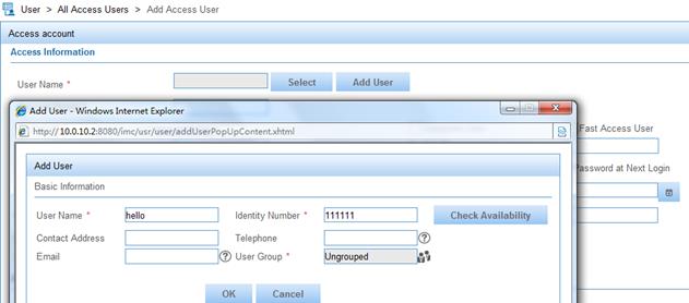
4. In the Access Information area, click the Add User button for the User Name field.
5. On the page that appears, configure the following parameters:
¡ Enter hello in the User Name field.
¡ Enter 111111 in the Identity Number field.
¡ Use the default settings for other parameters.
¡ Click OK.
Figure 5 Adding a user
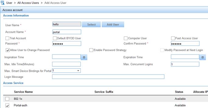
6. In the Access Information area, enter portal in the Account Name field and configure the password as 123456 for the account.
7. In the Access Service area, select the access service named Portal-auth.
8. Use the default settings for other parameters.
9. Click OK.
Figure 6 Configuring an access user
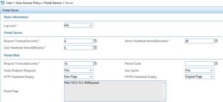
Configuring a portal page
1. Click the User tab.
2. From the navigation tree, select User Access Policy > Portal Service > Server.
3. Use the default settings for all parameters.
4. Click OK.
Figure 7 Configuring a portal page
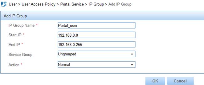
Adding an IP group for portal authentication
1. Click the User tab.
2. From the navigation tree, select User Access Policy > Portal Service > IP Group.
3. Click Add.
4. On the page that appears, configure the following parameters:
¡ Enter Portal_user in the IP Group Name field.
¡ Enter 192.168.0.0 in the Start IP field and 192.168.0.255 in the End IP field.
¡ Use the default settings for other parameters.
5. Click OK.
Figure 8 Adding an IP group
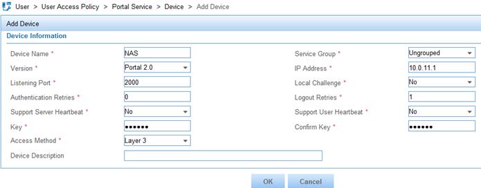
Configuring an access device for portal authentication
1. Click the User tab.
2. From the navigation tree, select User Access Policy > Portal Service > Device.
3. Click Add.
4. On the Add Device page, configure the following parameters:
¡ Enter NAS in the Device Name field.
¡ Enter 10.0.11.1 in the IP Address field.
¡ Enter portal in the Key and Confirm Key fields.
The key must be the same as that for the portal authentication server configured on Device B.
¡ Select Layer 3 from the Access Method list.
¡ Use the default settings for other parameters.
5. Click OK.
Figure 9 Adding an access device
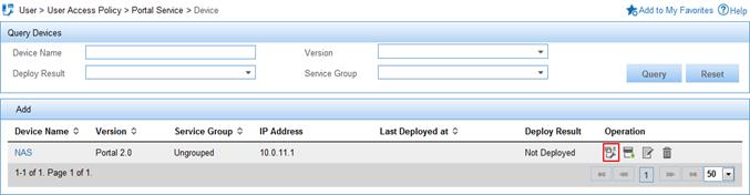
Configuring a port group for portal authentication
1. On the Device page, click the Port Group icon.
Figure 10 Accessing the Device page
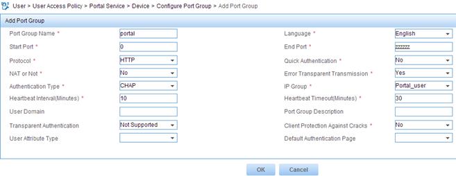
2. On the Configure Port Group page, click Add.
3. On the Add Port Group page, configure the following parameters:
¡ Enter portal in the Port Group Name field.
¡ Select Portal_user from the IP Group list.
¡ Use the default settings for other parameters.
4. Click OK.
Figure 11 Adding a port group
Verifying the configuration
A user can perform portal authentication by using the H3C iNode client or through a Web page. This example triggers portal authentication by accessing a Web page.
# Access a Web page through a Web browser on a host. You are redirected to the authentication page http://10.0.10.2:8080/portal. Enter the username portal and the password 123456 to log in. After passing the authentication, you are redirected to the authentication success page.
# Execute the display portal user command on Device B to display the portal user information.
[DeviceB] display portal user interface vlan-interface 11
Total portal users: 1
Username: portal
Portal server: newpt
State: Online
VPN instance: N/A
MAC IP Vlan Interface
0015-e9a6-7cfe 192.168.0.2 11 Vlan-interface11
Authorization information:
DHCP IP pool: N/A
User profile: N/A
Session group profile: N/A
ACL number: N/A
Inbound CAR: N/A
Outbound CAR: N/A
Configuration files
· Device A:
#
vlan 2
#
vlan 11
#
interface Vlan-interface2
ip address 192.168.0.1 255.255.255.0
#
interface Vlan-interface11
ip address 10.0.11.2 255.255.255.0
#
ip route-static 10.0.10.0 24 10.0.11.1
#
· Device B:
#
vlan 10 to 11
#
interface Vlan-interface10
ip address 10.0.10.1 255.255.255.0
#
interface Vlan-interface11
ip address 10.0.11.1 255.255.255.0
portal enable method layer3
portal bas-ip 10.0.11.1
portal apply web-server newpt
#
ip route-static 192.168.0.0 24 10.0.11.2
#
radius session-control enable
#
radius scheme imc
primary authentication 10.0.10.2
primary accounting 10.0.10.2
key authentication cipher $c$3$M30nGDQxiOCAxe2AJ9yEZdk8kjoWag==
key accounting cipher $c$3$M23dGDQxiOCAxe2BJ9yEZdk8kjoWag==
user-name-format without-domain
#
domain portal.com
authentication portal radius-scheme imc
authorization portal radius-scheme imc
accounting portal radius-scheme imc
#
domain default enable portal.com
#
portal web-server newpt
url http://10.0.10.2:8080/portal
#
portal server newpt
ip 10.0.10.2 key cipher $c$3$r0VxoIiBrpzju9h2akP4TxyknX8VTuYKfA==
#
Example: Configuring extended cross-subnet portal authentication
Network configuration
As shown in Figure 12, Device B supports portal authentication. An IMC server acts as a portal authentication server, a portal Web server, a RADIUS server, and a security policy server. The RADIUS server is used to perform AAA on portal users. The security policy server is deployed to perform security check on portal-authenticated users. In this example, the IMC server runs IMC PLAT 7.0 (E0202) and IMC UAM 7.0 (E0202).
Configure extended cross-subnet portal authentication. Before passing portal authentication, a host can access only the portal Web server. After the host passes authentication, the security policy server performs a security check on the host. If the host fails the security check, the host is permitted to access only the Patch/Virus definitions update server. After passing the security check, the host can access resources in the IP network.
Analysis
To enable Device B to perform cross-subnet portal authentication through RADIUS, you must complete the following tasks:
· Configure the portal authentication and Web server, and enable cross-subnet portal authentication.
· Configure the RADIUS scheme. Specify the AAA server for the scheme and apply the scheme to the portal authentication domain.
To perform security check on authenticated users, you must complete the following tasks:
· On Device B, create an ACL (ACL 3000 in this example) for users who fail security checks, and an ACL (ACL 3001 in this example) for users who pass security checks.
· On the security policy server, specify ACL 3000 as the isolation ACL and ACL 3001 as the security ACL.
Applicable hardware and software versions
The following matrix shows the hardware and software versions to which this configuration example is applicable:
|
Hardware |
Software version |
|
S6800 switch series S6860 switch series S6861 switch series |
Release 2702 |
Procedures
Configuring Device A
# Configure VLAN-interface 2 and VLAN-interface 11, and assign them IP addresses.
<DeviceA> system-view
[DeviceA] vlan 2
[DeviceA-vlan2] quit
[DeviceA] vlan 11
[DeviceA-vlan11] quit
[DeviceA] interface vlan-interface 2
[DeviceA-Vlan-interface2] ip address 192.168.0.1 24
[DeviceA-Vlan-interface2] quit
[DeviceA] interface vlan-interface 11
[DeviceA-Vlan-interface11] ip address 10.0.11.2 24
[DeviceA-Vlan-interface11] quit
# Assign the corresponding physical interfaces to the VLANs. (Details not shown.)
# Configure a static route to the RADIUS, portal, and security policy server.
[DeviceA] ip route-static 10.0.10.0 255.255.255.0 10.0.11.1
# Configure a static route to the patch and virus definitions update server.
[DeviceA] ip route-static 10.0.12.0 255.255.255.0 10.0.11.1
Configuring Device B
# Configure VLAN-interface 10, VLAN-interface 11, and VLAN-interface 12, and assign them IP addresses.
<DeviceB> system-view
[DeviceB] vlan 10
[DeviceB-vlan10] quit
[DeviceB] vlan 11
[DeviceB-vlan11] quit
[DeviceB] vlan 12
[DeviceB-vlan12] quit
[DeviceB] interface vlan-interface 11
[DeviceB-Vlan-interface11] ip address 10.0.11.1 24
[DeviceB-Vlan-interface11] quit
[DeviceB] interface vlan-interface 10
[DeviceB-Vlan-interface10] ip address 10.0.10.1 24
[DeviceB-Vlan-interface10] quit
[DeviceB] interface vlan-interface 12
[DeviceB-Vlan-interface12] ip address 10.0.12.1 24
[DeviceB-Vlan-interface12] quit
# Configure portal authentication server newpt.
[DeviceB] portal server newpt
[DeviceB-portal-server-newpt] ip 10.0.10.2 key simple portal
[DeviceB-portal-server-newpt] port 50100
[DeviceB-portal-server-newpt] quit
# Configure portal Web server newpt. The URL must be the same as the URL configured for the portal page on the portal Web server.
[DeviceB] portal web-server newpt
[DeviceB-portal-websvr-newpt] url http://10.0.10.2:8080/portal
[DeviceB-portal-websvr-newpt] quit
# Enable cross-subnet authentication on VLAN-interface 11, the interface connected to Device A.
[DeviceB] interface Vlan-interface 11
[DeviceB-Vlan-interface11] portal enable method layer3
# Configure the BAS-IP as 10.0.11.1 for portal packets sent from VLAN-interface 11 to the portal authentication server.
[DeviceB-Vlan-interface11] portal bas-ip 10.0.11.1
# Specify portal Web server newpt on VLAN-interface 11.
[DeviceB-Vlan-interface11] portal apply web-server newpt
[DeviceB-Vlan-interface11] quit
# Create a static route to Department A.
[DeviceB] ip route-static 192.168.0.0 255.255.255.0 10.0.11.2
# Create RADIUS scheme named imc and enter its view.
[DeviceB] radius scheme imc
# Specify the primary authentication server and primary accounting server, and configure the keys for communication with the server.
[DeviceB-radius-imc] primary authentication 10.0.10.2
[DeviceB-radius-imc] primary accounting 10.0.10.2
[DeviceB-radius-imc] key authentication simple expert
[DeviceB-radius-imc] key accounting simple expert
# Exclude the ISP domain name from the username sent to the RADIUS server.
[DeviceB-radius-imc] user-name-format without-domain
[DeviceB-radius-imc] quit
# Enable RADIUS session control.
[DeviceB] radius session-control enable
# Create an ISP domain named portal.com and enter its view.
[DeviceB] domain portal.com
# Configure AAA methods for the ISP domain.
[DeviceB-isp-portal.com] authentication portal radius-scheme imc
[DeviceB-isp-portal.com] authorization portal radius-scheme imc
[DeviceB-isp-portal.com] accounting portal radius-scheme imc
[DeviceB-isp-portal.com] quit
# Specify domain portal.com as the default ISP domain. If a user enters the username without the ISP domain name at login, the AAA methods of the default domain are used for the user.
[DeviceB] domain default enable portal.com
# Configure ACL 3000 to permit access only to the Patch/Virus definitions update server. Configure ACL 3001 to permit access to any IP address.
[DeviceB] acl number 3000
[DeviceB-acl-adv-3000] rule permit ip destination 10.0.12.2 0
[DeviceB-acl-adv-3000] rule deny ip
[DeviceB-acl-adv-3000] quit
[DeviceB] acl number 3001
[DeviceB-acl-adv-3001] rule permit ip
[DeviceB-acl-adv-3001] quit
Configuring the RADIUS, portal, and security policy server
# Configure the RADIUS server and portal server. For more information, see "Configuring the RADIUS and portal server."
# Configure the security policy server. Make sure you specify ACL 3000 as the isolation ACL and ACL 3001 as the security ACL.
Verifying the configuration
A user can perform the extended cross-subnet authentication only by using the H3C iNode client.
# Open the iNode client on a host, and create a portal connection. Enter the username and password and click Connect. The user passes the portal authentication.
# On the iNode client, check security check information. The user failed to pass the security check.
# Display portal users on Device B to verify that ACL 3000 has been deployed to the portal user.
[DeviceB] display portal user all
Total portal users: 1
Username: portal
Portal server: newpt
State: Online
VPN instance: N/A
MAC IP VLAN Interface
0015-e9a6-7cfe 192.168.0.2 11 Vlan-interface11
Authorization information:
DHCP IP pool: N/A
User profile: N/A
Session group profile: N/A
ACL number: 3000
Inbound CAR: N/A
Outbound CAR: N/A
# Update the virus database on the host to meet the security requirement.
# On the iNode client, disconnect the portal connection and then log in again. Check security check information. The iNode client displays that the host successfully passed the security check.
# Display portal user information on Device B to verify that ACL 3001 has been deployed to the portal user.
[DeviceB]display portal user all
Total portal users: 1
Username: portal
Portal server: newpt
State: Online
Authorization ACL: 3001
VPN instance: N/A
MAC IP VLAN Interface
0015-e9a6-7cfe 192.168.0.2 11 Vlan-interface11
Authorization information:
DHCP IP pool: N/A
User profile: N/A
Session group profile: N/A
ACL number: 3001
Inbound CAR: N/A
Outbound CAR: N/A
Configuration files
· Device A:
#
vlan 2
#
vlan 11
#
interface Vlan-interface2
ip address 192.168.0.1 255.255.255.0
#
interface Vlan-interface11
ip address 10.0.11.2 255.255.255.0
#
ip route-static 10.0.10.0 24 10.0.11.1
ip route-static 10.0.12.0 24 10.0.11.1
#
· Device B:
#
vlan 10 to 12
#
interface Vlan-interface10
ip address 10.0.10.1 255.255.255.0
#
interface Vlan-interface11
ip address 10.0.11.1 255.255.255.0
portal enable method layer3
portal bas-ip 10.0.11.1
portal apply web-server newpt
#
interface Vlan-interface12
ip address 10.0.12.1 255.255.255.0
#
ip route-static 192.168.0.0 24 10.0.11.2
#
acl number 3000
rule 0 permit ip destination 10.0.12.2 0
rule 5 deny ip
#
acl number 3001
rule 0 permit ip
#
radius session-control enable
#
radius scheme imc
primary authentication 10.0.10.2
primary accounting 10.0.10.2
key authentication cipher $c$3$M30nGDQxiOCAxe2AJ9yEZdk8kjoWag==
key accounting cipher $c$3$M23dGDQxiOCAxe2BJ9yEZdk8kjoWag==
user-name-format without-domain
#
domain portal.com
authentication portal radius-scheme imc
authorization portal radius-scheme imc
accounting portal radius-scheme imc
#
domain default enable portal.com
#
portal web-server newpt
url http://10.0.10.2:8080/portal
#
portal server newpt
ip 10.0.10.2 key cipher $c$3$r0VxoIiBrpzju9h2akP4TxyknX8VTuYKfA==
#
Example: Configuring direct portal authentication
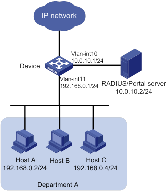
Network configuration
As shown in Figure 13, hosts in Department A are directly connected to the device. An IMC server acts as both a portal authentication server, a portal Web server, and a RADIUS server. The RADIUS server is used to perform AAA on portal users. In this example, the IMC server runs on IMC PLAT 7.0 (E0202) and IMC UAM 7.0 (E0202).
Configure direct portal authentication. The hosts can access only the portal server before passing authentication and can access other network resources after passing authentication.
Analysis
To enable Device to perform portal authentication through RADIUS, you must complete the following tasks:
· Configure the portal authentication and Web server, and enable direct portal authentication.
· Configure the RADIUS scheme. Specify the AAA server for the scheme and apply the scheme to the portal authentication domain.
Applicable hardware and software versions
The following matrix shows the hardware and software versions to which this configuration example is applicable:
|
Hardware |
Software version |
|
S6800 switch series S6860 switch series S6861 switch series |
Release 2702 |
Procedures
Configuring the device
# Configure VLAN-interface 10 and VLAN-interface 11, and assign them IP addresses.
<Device> system-view
[Device] vlan 10
[Device-vlan10] quit
[Device] vlan 11
[Device-vlan11] quit
[Device] interface vlan-interface 11
[Device-Vlan-interface11] ip address 192.168.0.1 24
[Device-Vlan-interface11] quit
[Device] interface vlan-interface 10
[Device-Vlan-interface10] ip address 10.0.10.1 24
[Device-Vlan-interface10] quit
# Configure portal authentication server newpt.
[Device] portal server newpt
[Device-portal-server-newpt] ip 10.0.10.2 key simple portal
[Device-portal-server-newpt] port 50100
[Device-portal-server-newpt] quit
# Configure portal Web server newpt. The URL must be the same as the URL configured for the portal page on the portal Web server.
[Device] portal web-server newpt
[Device-portal-websvr-newpt] url http://10.0.10.2:8080/portal
[Device-portal-websvr-newpt] quit
# Enable direct portal authentication on VLAN-interface 11.
[Device] interface Vlan-interface 11
[Device-Vlan-interface11] portal enable method direct
# Configure the BAS-IP as 192.168.0.1 for portal packets sent from VLAN-interface 11 to the portal authentication server.
[Device-Vlan-interface11] portal bas-ip 192.168.0.1
# Specify portal Web server newpt on VLAN-interface 11.
[Device-Vlan-interface11] portal apply web-server newpt
[Device-Vlan-interface11] quit
# Create a RADIUS scheme named imc and enter its view.
[Device] radius scheme imc
# Specify the primary authentication server and primary accounting server, and configure the keys for communication with the server.
[Device-radius-imc] primary authentication 10.0.10.2
[Device-radius-imc] primary accounting 10.0.10.2
[Device-radius-imc] key authentication simple expert
[Device-radius-imc] key accounting simple expert
# Exclude the ISP domain name from the username sent to the RADIUS server.
[Device-radius-imc] user-name-format without-domain
[Device-radius-imc] quit
# Enable the RADIUS session-control feature.
[Device] radius session-control enable
# Create an ISP domain named portal.com and enter its view.
[Device] domain portal.com
# Configure AAA methods for the ISP domain.
[Device-isp-portal.com] authentication portal radius-scheme imc
[Device-isp-portal.com] authorization portal radius-scheme imc
[Device-isp-portal.com] accounting portal radius-scheme imc
[Device-isp-portal.com] quit
# Configure domain portal.com as the default ISP domain. If a user enters the username without the ISP domain name at login, the authentication and accounting methods of the default domain are used for the user.
[Device] domain default enable portal.com
Configuring the RADIUS and portal server
Configure the RADIUS server and portal server. For more information, see "Configuring the RADIUS and portal server."
When you configuring an access device for portal authentication (as shown in Figure 13), select Directly Selected from the Access Method list, and enter 192.168.0.1 in the IP Address field.
Verifying the configuration
A user can perform portal authentication by using the H3C iNode client or through a Web page. This example uses the Web page.
# Access a Web page through a Web browser on a host. You are redirected to the authentication page http://10.0.10.2:8080/portal. Enter the username portal and the password 123456 to log in. After passing the authentication, you are redirected to the authentication success page.
# Execute the display portal user command to display portal user information on Device.
[Device] display portal user interface vlan-interface 11
Total portal users: 1
Username: portal
Portal server: newpt
State: Online
VPN instance: N/A
MAC IP Vlan Interface
0015-e9a6-7cfe 192.168.0.2 11 Vlan-interface11
Authorization information:
DHCP IP pool: N/A
User profile: N/A
Session group profile: N/A
ACL number: N/A
Inbound CAR: N/A
Outbound CAR: N/A
Configuration files
vlan 10 to 11
#
interface Vlan-interface10
ip address 10.0.10.1 255.255.255.0
#
interface Vlan-interface11
ip address 192.168.0.1 255.255.255.0
portal enable method direct
portal bas-ip 192.168.0.1
portal apply web-server newpt
#
radius session-control enable
#
radius scheme imc
primary authentication 10.0.10.2
primary accounting 10.0.10.2
key authentication cipher $c$3$M30nGDQxiOCAxe2AJ9yEZdk8kjoWag==
key accounting cipher $c$3$M23dGDQxiOCAxe2BJ9yEZdk8kjoWag==
user-name-format without-domain
#
domain portal.com
authentication portal radius-scheme imc
authorization portal radius-scheme imc
accounting portal radius-scheme imc
#
domain default enable portal.com
#
portal web-server newpt
url http://10.0.10.2:8080/portal
#
portal server newpt
ip 10.0.10.2 key cipher $c$3$r0VxoIiBrpzju9h2akP4TxyknX8VTuYKfA==
#
Related documentation
· H3C S6800[S6860][S6861] (R27xx) & S6820 (R630x) Switch Series Security Configuration Guide
· H3C S6800[S6860][S6861] (R27xx) & S6820 (R630x) Switch Series Security Command Reference