- Table of Contents
-
- H3C S6800 & S6860 & S6861 Switches Configuration Examples-Release 27xx-6W100
- 01-Login Management Configuration Examples
- 02-RBAC Configuration Examples
- 03-Software Upgrade Examples
- 04-ISSU Configuration Examples
- 05-Software Patching Examples
- 06-Ethernet Link Aggregation Configuration Examples
- 07-Port Isolation Configuration Examples
- 08-Spanning Tree Configuration Examples
- 09-VLAN Configuration Examples
- 10-VLAN Tagging Configuration Examples
- 11-PBB Configuration Examples
- 12-DHCP Snooping Configuration Examples
- 13-Cross-Subnet Dynamic IP Address Allocation Configuration Examples
- 14-IPv6 over IPv4 Manual Tunneling with OSPFv3 Configuration Examples
- 15-ISATAP Tunnel and 6to4 Tunnel Configuration Examples
- 16-IPv6 over IPv4 GRE Tunnel Configuration Examples
- 17-GRE with OSPF Configuration Examples
- 18-OSPF Configuration Examples
- 19-IS-IS Configuration Examples
- 20-BGP Configuration Examples
- 21-Policy-Based Routing Configuration Examples
- 22-OSPFv3 Configuration Examples
- 23-IPv6 IS-IS Configuration Examples
- 24-Routing Policy Configuration Examples
- 25-IGMP Snooping Configuration Examples
- 26-IGMP Configuration Examples
- 27-BIDIR-PIM Configuration Examples
- 28-Multicast VPN Configuration Examples
- 29-MLD Snooping Configuration Examples
- 30-IPv6 Multicast VLAN Configuration Examples
- 31-Basic MPLS Configuration Examples
- 32-MPLS L3VPN Configuration Examples
- 33-ACL Configuration Examples
- 34-Control Plane-Based QoS Policy Configuration Examples
- 35-Traffic Policing Configuration Examples
- 36-GTS and Rate Limiting Configuration Examples
- 37-Priority Mapping and Queue Scheduling Configuration Examples
- 38-Traffic Filtering Configuration Examples
- 39-AAA Configuration Examples
- 40-Port Security Configuration Examples
- 41-Portal Configuration Examples
- 42-SSH Configuration Examples
- 43-IP Source Guard Configuration Examples
- 44-Ethernet OAM Configuration Examples
- 45-CFD Configuration Examples
- 46-DLDP Configuration Examples
- 47-VRRP Configuration Examples
- 48-BFD Configuration Examples
- 49-NTP Configuration Examples
- 50-SNMP Configuration Examples
- 51-NQA Configuration Examples
- 52-Mirroring Configuration Examples
- 53-sFlow Configuration Examples
- 54-FCoE Configuration Examples
- 55-SPBM Configuration Examples
- 56-OpenFlow Configuration Examples
- 57-MAC Address Table Configuration Examples
- 58-Static Multicast MAC Address Entry Configuration Examples
- 59-IP Unnumbered Configuration Examples
- 60-MVRP Configuration Examples
- 61-MCE Configuration Examples
- 62-Congestion Avoidance and Queue Scheduling Configuration Examples
- 63-Attack Protection Configuration Examples
- 64-Smart Link Configuration Examples
- 65-RRPP Configuration Examples
- 66-BGP Route Selection Configuration Examples
- 67-IS-IS Route Summarization Configuration Examples
- 68-IRF Configuration Examples
- 69-MPLS OAM Configuration Examples
- 70-MPLS TE Configuration Examples
- 71-GRE with VPN Configuration Examples
- 72-VXLAN Configuration Examples
- 73-DRNI Configuration Examples
- 74-IRF 3.1 Configuration Examples
- 75-DRNI and EVPN Configuration Examples
- 76-EVPN-DCI over an MPLS L3VPN Network Configuration Examples
- 77-VCF Fabric Configuration Examples
- 78-PTP Configuration Examples
- 79-S-MLAG Configuration Examples
- 80-MPLS SR Configuration Examples
- 81-Puppet Configuration Examples
- Related Documents
-
| Title | Size | Download |
|---|---|---|
| 71-GRE with VPN Configuration Examples | 183.55 KB |
|
|
|
H3C S6800 & S6860 & S6861 Switches |
|
GRE with VPN Configuration Examples |
|
|
Copyright © 2019 New H3C Technologies Co., Ltd. All rights reserved.
No part of this manual may be reproduced or transmitted in any form or by any means without prior written consent of New H3C Technologies Co., Ltd.
Except for the trademarks of New H3C Technologies Co., Ltd., any trademarks that may be mentioned in this document are the property of their respective owners.
The information in this document is subject to change without notice.
Introduction
This document provides GRE with VPN configuration examples.
In an MPLS VPN network where a CE and a PE cannot be connected directly, you can deploy a GRE tunnel to provide a logical direct connection between them.
Prerequisites
The configuration examples in this document were created and verified in a lab environment, and all the devices were started with the factory default configuration. When you are working on a live network, make sure you understand the potential impact of every command on your network.
This document assumes that you have basic knowledge of GRE and MPLS L3VPN.
Example: Configuring GRE with VPN
Network configuration
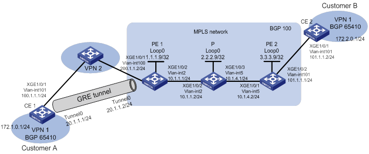
As shown in Figure 1:
· Customer A and Customer B belong to VPN network vpn1.
· CE 1 and CE 2 are the edge devices of customer network vpn1.
· PE 1 and PE 2 are the edge devices of the MPLS network.
· CE 1 and PE 1 are interconnected through a VPN network named vpn2.
Configure the following settings for Customer A and Customer B to communicate with each other through the MPLS and VPN networks:
· Set up a point-to-point GRE tunnel between CE 1 and PE 1 and configure static routes for them to reach each other.
· Configure an IGP routing protocol in the MPLS network to ensure IP connectivity among the PE and P devices. In this example, OSPF is used.
· Configure LDP in the MPLS network to distribute public network labels (outer labels) of packets from VPN network vpn1.
· Configure MP-BGP and establish peer relationship between the PEs so that the PEs can advertise private network routing information and distribute private network labels (inner labels).
Applicable hardware and software versions
The following matrix shows the hardware and software versions to which this configuration example is applicable:
|
Hardware |
Software version |
|
S6800 switch series S6860 switch series S6861 switch series |
Release 2702 |
Restrictions and guidelines
Associating an interface with a VPN instance clears the IP address configuration on the interface. As a best practice, associate the interface with the VPN instance before you configure other settings on the interface.
Procedures
Configuring OSPF in the MPLS network
1. Configure PE 1:
# Configure IP addresses for Loopback 0 and VLAN-interface 2.
<PE1> system-view
[PE1] interface loopback 0
[PE1-LoopBack0] ip address 1.1.1.9 32
[PE1-LoopBack0] quit
[PE1] vlan 2
[PE1-vlan2] port ten-gigabitethernet 1/0/2
[PE1-vlan2] quit
[PE1] interface vlan-interface 2
[PE1-Vlan-interface2] ip address 10.1.1.1 24
[PE1-Vlan-interface2] quit
# Configure OSPF to advertise routes for the specified networks.
[PE1] ospf
[PE1-ospf-1] area 0
[PE1-ospf-1-area-0.0.0.0] network 10.1.1.0 0.0.0.255
[PE1-ospf-1-area-0.0.0.0] network 1.1.1.9 0.0.0.0
[PE1-ospf-1-area-0.0.0.0] quit
[PE1-ospf-1] quit
2. Configure P:
# Configure IP addresses for Loopback 0, VLAN-interface 2, and VLAN-interface 5.
<P> system-view
[P] interface loopback 0
[P-LoopBack0] ip address 2.2.2.9 32
[P-LoopBack0] quit
[P] vlan 2
[P-vlan2] port ten-gigabitethernet 1/0/2
[P-vlan2] quit
[P] vlan 5
[P-vlan5] port ten-gigabitethernet 1/0/3
[P-vlan5] quit
[P] interface vlan-interface 2
[P-Vlan-interface2] ip address 10.1.1.2 24
[P-Vlan-interface2] quit
[P] interface vlan-interface 5
[P-Vlan-interface5] ip address 10.1.4.1 24
[P-Vlan-interface5] quit
# Configure OSPF to advertise routes for the specified networks.
[P] ospf
[P-ospf-1] area 0
[P-ospf-1-area-0.0.0.0] network 10.1.1.0 0.0.0.255
[P-ospf-1-area-0.0.0.0] network 10.1.4.0 0.0.0.255
[P-ospf-1-area-0.0.0.0] network 2.2.2.9 0.0.0.0
[P-ospf-1-area-0.0.0.0] quit
[P-ospf-1] quit
3. Configure PE 2:
# Configure IP addresses for Loopback 0 and VLAN-interface 5.
<PE2> system-view
[PE2] interface loopback 0
[PE2-LoopBack0] ip address 3.3.3.9 32
[PE2-LoopBack0] quit
[PE2] vlan 5
[PE2-vlan5] port ten-gigabitethernet 1/0/1
[PE2-vlan5] quit
[PE2] interface vlan-interface 5
[PE2-Vlan-interface5] ip address 10.1.4.2 24
[PE2-Vlan-interface5] quit
# Configure OSPF to advertise routes for the specified networks.
[PE2] ospf
[PE2-ospf-1] area 0
[PE2-ospf-1-area-0.0.0.0] network 10.1.4.0 0.0.0.255
[PE2-ospf-1-area-0.0.0.0] network 3.3.3.9 0.0.0.0
[PE2-ospf-1-area-0.0.0.0] quit
[PE2-ospf-1] quit
4. Verify that PE 1, P, and PE 2 have established OSPF neighbor relationship. This example uses PE 1 for illustration.
[PE1] display ospf peer verbose
OSPF Process 1 with Router ID 1.1.1.9
Neighbors
Area 0.0.0.0 interface 10.1.1.1(Vlan-interface2)'s neighbors
Router ID: 2.2.2.9 Address: 10.1.1.2 GR State: Normal
State: Full Mode: Nbr is Master Priority: 1
DR: 10.1.1.2 BDR: 10.1.1.1 MTU: 0
Options is 0x02 (-|-|-|-|-|-|E|-)
Dead timer due in 38 sec
Neighbor is up for 17:30:25
Authentication Sequence: [ 0 ]
Neighbor state change count: 6
BFD status: Disabled
[PE1] display ip routing-table protocol ospf
Summary Count : 5
OSPF Routing table Status : <Active>
Summary Count : 3
Destination/Mask Proto Pre Cost NextHop Interface
2.2.2.9/32 OSPF 10 1 10.1.1.2 Vlan2
3.3.3.9/32 OSPF 10 2 10.1.1.2 Vlan2
10.1.4.0/24 OSPF 10 2 10.1.1.2 Vlan2
OSPF Routing table Status : <Inactive>
Summary Count : 2
Destination/Mask Proto Pre Cost NextHop Interface
1.1.1.9/32 OSPF 10 0 1.1.1.9 Loop0
10.1.1.0/24 OSPF 10 1 10.1.1.1 Vlan2
Establishing LDP LSPs in the MPLS network
1. Configure PE 1:
# Configure the LSR ID as 1.1.1.9 and enable LDP globally.
[PE1] mpls lsr-id 1.1.1.9
[PE1] mpls ldp
[PE1-ldp] quit
# Enable MPLS and IPv4 LDP on VLAN-interface 2.
[PE1] interface vlan-interface 2
[PE1-Vlan-interface2] mpls enable
[PE1-Vlan-interface2] mpls ldp enable
[PE1-Vlan-interface2] quit
2. Configure P:
# Configure the LSR ID as 2.2.2.9 and enable LDP globally.
[P] mpls lsr-id 2.2.2.9
[P] mpls ldp
[P-ldp] quit
# Enable MPLS and IPv4 LDP on VLAN-interface 2.
[P] interface vlan-interface 2
[P-Vlan-interface2] mpls enable
[P-Vlan-interface2] mpls ldp enable
[P-Vlan-interface2] quit
# Enable MPLS and IPv4 LDP on VLAN-interface 5.
[P] interface vlan-interface 5
[P-Vlan-interface5] mpls enable
[P-Vlan-interface5] mpls ldp enable
[P-Vlan-interface5] quit
3. Configure PE 2:
# Configure the LSR ID as 3.3.3.9 and enable LDP globally.
[PE2] mpls lsr-id 3.3.3.9
[PE2] mpls ldp
[PE2-ldp] quit
# Enable MPLS and IPv4 LDP on VLAN-interface 5.
[PE2] interface vlan-interface 5
[PE2-Vlan-interface5] mpls enable
[PE2-Vlan-interface5] mpls ldp enable
[PE2-Vlan-interface5] quit
4. Verify that PE 1, P, and PE 2 have established LDP sessions. This example uses PE 1 for illustration.
[PE1] display mpls ldp peer
Total number of peers: 1
Peer LDP ID State Role GR MD5 KA Sent/Rcvd
2.2.2.9:0 Operational Passive Off Off 5/5
[PE1] display mpls ldp lsp
Status Flags: * - stale, L - liberal, B - backup
FECs: 4 Ingress: 1 Transit: 1 Egress: 3
FEC In/Out Label Nexthop OutInterface
1.1.1.9/32 3/-
-/1151(L)
2.2.2.9/32 -/3 10.1.1.2 Vlan2
1151/3 10.1.1.2 Vlan2
3.3.3.9/32 -/1150 10.1.1.2 Vlan2
1150/1150 10.1.1.2 Vlan2
Configuring GRE and VPN instances
1. Configure VPN instance vpn1 on PE 1:
# Create VPN instance vpn1.
[PE1] ip vpn-instance vpn1
# Configure an RD for the VPN instance.
[PE1-vpn-instance-vpn1] route-distinguisher 100:1
# Configure route targets for the VPN instance.
[PE1-vpn-instance-vpn1] vpn-target 100:1 import-extcommunity
[PE1-vpn-instance-vpn1] vpn-target 100:1 export-extcommunity
[PE1-vpn-instance-vpn1] quit
# Associate VLAN-interface 100 with VPN instance vpn1.
[PE1] vlan 100
[PE1-vlan100] port ten-gigabitethernet 1/0/1
[PE1-vlan100] quit
[PE1] interface vlan-interface 100
[PE1-Vlan-interface100] ip binding vpn-instance vpn1
[PE1-Vlan-interface100] ip address 200.1.1.2 24
[PE1-Vlan-interface100] quit
2. Configure VPN instance vpn1 on CE 1:
# Create VPN instance vpn1.
[CE1] ip vpn-instance vpn1
# Configure an RD for the VPN instance.
[CE1-vpn-instance-vpn1] route-distinguisher 100:1
# Configure route targets for the VPN instance.
[CE1-vpn-instance-vpn1] vpn-target 100:1 import-extcommunity
[CE1-vpn-instance-vpn1] vpn-target 100:1 export-extcommunity
[CE1-vpn-instance-vpn1] quit
# Associate VLAN-interface 101 with VPN instance vpn1.
[CE1] vlan 101
[CE1-vlan101] port ten-gigabitethernet 1/0/1
[CE1-vlan101] quit
[CE1] interface vlan-interface 101
[CE1-Vlan-interface101] ip binding vpn-instance vpn1
[CE1-Vlan-interface101] ip address 100.1.1.1 24
[CE1-Vlan-interface101] quit
3. Configure GRE on CE 1:
# Create service loopback group 1, and specify its service type as Tunnel.
[CE1] service-loopback group 1 type tunnel
# Add Ten-GigabitEthernet 1/0/3 to service loopback group 1.
[CE1] interface ten-gigabitethernet 1/0/3
[CE1-Ten-GigabitEthernet1/0/3] port service-loopback group 1
[CE1-Ten-GigabitEthernet1/0/3] quit
# Create tunnel interface Tunnel 0, and specify the tunnel mode as GRE/IPv4.
[CE1] interface tunnel 0 mode gre
# Specify the VPN instance to which the tunnel source belongs.
[CE1-Tunnel0] ip binding vpn-instance vpn1
# Configure an IP address for tunnel interface Tunnel 0.
[CE1-Tunnel0] ip address 20.1.1.1 255.255.255.0
# Configure the source address of tunnel interface Tunnel 0 as the IP address of VLAN-interface 101 on CE 1.
[CE1-Tunnel0] source vlan-interface 101
# Configure the destination address of the tunnel interface as the IP address of VLAN-interface 100 on PE 1.
[CE1-Tunnel0] destination 200.1.1.2
# Specify the VPN instance to which the tunnel destination belongs.
[CE1-Tunnel0] tunnel vpn-instance vpn1
[CE1-Tunnel0] quit
# Configure a static route from Customer A through tunnel interface Tunnel 0 to Customer B.
[CE1] ip route-static vpn-instance vpn1 172.2.0.0 24 tunnel 0
4. Configure GRE on PE 1:
# Create service loopback group 1, and specify its service type as Tunnel.
[PE1] service-loopback group 1 type tunnel
# Add Ten-GigabitEthernet 1/0/3 to service loopback group 1.
[PE1] interface ten-gigabitethernet 1/0/3
[PE1-Ten-GigabitEthernet1/0/3] port service-loopback group 1
[PE1-Ten-GigabitEthernet1/0/3] quit
# Create tunnel interface Tunnel 0, and specify the tunnel mode as GRE/IPv4.
[PE1] interface tunnel 0 mode gre
# Specify the VPN instance to which the tunnel source belongs.
[PE1-Tunnel0] ip binding vpn-instance vpn1
# Configure an IP address for tunnel interface Tunnel 0.
[PE1-Tunnel0] ip address 20.1.1.2 255.255.255.0
# Configure the source address of tunnel interface Tunnel 0 as the IP address of VLAN-interface 100 on PE 1.
[PE1-Tunnel0] source vlan-interface 100
# Configure the destination address of the tunnel interface as the IP address of VLAN-interface 101 on CE 1.
[PE1-Tunnel0] destination 100.1.1.1
# Specify the VPN instance to which the tunnel destination belongs.
[PE1-Tunnel0] tunnel vpn-instance vpn1
[PE1-Tunnel0] quit
# Configure a static route from Customer B through tunnel interface Tunnel 0 to Customer A.
[PE1] ip route-static vpn-instance vpn1 172.1.0.0 24 Tunnel 0
5. Configure VPN instance vpn1 on PE 2:
# Create VPN instance vpn1.
[PE2] ip vpn-instance vpn1
# Configure an RD for the VPN instance.
[PE2-vpn-instance-vpn1] route-distinguisher 100:1
# Configure route targets for the VPN instance. Make sure the import route target on PE 2 is the same as the export route target on PE 1 and the export route target on PE 2 is the same as the import route target on PE 1.
[PE2-vpn-instance-vpn1] vpn-target 100:1 import-extcommunity
[PE2-vpn-instance-vpn1] vpn-target 100:1 export-extcommunity
[PE2-vpn-instance-vpn1] quit
# Associate VLAN-interface 101 with VPN instance vpn1.
[PE2] vlan 101
[PE2-vlan101] port ten-gigabitethernet 1/0/2
[PE2-vlan101] quit
[PE2] interface vlan-interface 101
[PE2-Vlan-interface101] ip binding vpn-instance vpn1
[PE2-Vlan-interface101] ip address 101.1.1.1 24
[PE2-Vlan-interface101] quit
6. Configure IP addresses for interfaces on CE 2, as shown in Figure 1. (Details not shown.)
7. Verify the configuration. This example uses PE 2 for illustration.
# Display VPN instance information.
[PE2] display ip vpn-instance
Total VPN-Instances configured : 1
VPN-Instance Name RD Create time
vpn1 100:1 2016/06/22 13:20:08
# Verify that PE 2 can ping CE 2.
[PE2] ping -vpn-instance vpn1 101.1.1.2
Ping 10.1.4.2 (101.1.1.2): 56 data bytes, press CTRL_C to break
56 bytes from 101.1.1.2: icmp_seq=0 ttl=255 time=1.000 ms
56 bytes from 101.1.1.2: icmp_seq=1 ttl=255 time=2.000 ms
56 bytes from 101.1.1.2: icmp_seq=2 ttl=255 time=0.000 ms
56 bytes from 101.1.1.2: icmp_seq=3 ttl=255 time=1.000 ms
56 bytes from 101.1.1.2: icmp_seq=4 ttl=255 time=0.000 ms
--- Ping statistics for 10.1.1.1 ---
5 packet(s) transmitted, 5 packet(s) received, 0.0% packet loss
round-trip min/avg/max/std-dev = 0.000/0.800/2.000/0.748 ms
Establishing EBGP peer relationship between PEs and CEs and redistributing VPN routes
1. Configure PE 1:
# Enable BGP instance default, set the local AS number to 100, and enter BGP instance view.
[PE1] bgp 100
# Specify CE 1 as a BGP peer and set its AS number to 65410.
[PE1-bgp-default] ip vpn-instance vpn1
[PE1-bgp-default-vpn1] peer 20.1.1.1 as-number 65410
# Redistribute the direct routes of PE 1 to BGP-VPN IPv4 unicast address family.
[PE1-bgp-default-vpn1] address-family ipv4 unicast
[PE1-bgp-default-ipv4-vpn1] peer 20.1.1.1 enable
[PE1-bgp-default-ipv4-vpn1] import-route direct
[PE1-bgp-default-ipv4-vpn1] quit
[PE1-bgp-default-vpn1] quit
2. Configure PE 2:
# Enable BGP instance default, set the local AS number to 100, and enter BGP instance view.
[PE2] bgp 100
# Specify CE 2 as a BGP peer and set its AS number to 65410.
[PE2-bgp-default] ip vpn-instance vpn1
[PE2-bgp-default-vpn1] peer 101.1.1.2 as-number 65410
# Redistribute the direct routes of PE 2 to BGP-VPN IPv4 unicast address family.
[PE2-bgp-default-vpn1] address-family ipv4 unicast
[PE2-bgp-default-ipv4-vpn1] peer 101.1.1.2 enable
[PE2-bgp-default-ipv4-vpn1] import-route direct
[PE2-bgp-default-ipv4-vpn1] quit
[PE2-bgp-default-vpn1] quit
3. Configure CE 1:
# Enable BGP instance default, set the local AS number to 65410, and enter BGP instance view.
<CE1> system-view
[CE1] bgp 65410
# Specify PE 1 as a BGP peer and set its AS number to 100.
[CE1-bgp-default] peer 20.1.1.2 as-number 100
# Enter BGP IPv4 unicast address family view, and enable BGP to exchange IPv4 unicast routing information with peer 20.1.1.2.
[CE1-bgp-default] address-family ipv4 unicast
[CE1-bgp-default-ipv4] peer 20.1.1.2 enable
# Redistribute direct routes to BGP IPv4 unicast address family.
[CE1-bgp-default-ipv4] import-route direct
[CE1-bgp-default-ipv4] quit
[CE1-bgp-default] quit
4. Configure CE 2:
# Enable BGP instance default, set the local AS number to 65410, and enter BGP instance view.
<CE2> system-view
[CE2] bgp 65410
# Specify PE 2 as a BGP peer and set its AS number to 100.
[CE2-bgp-default] peer 101.1.1.1 as-number 100
# Enter BGP IPv4 unicast address family view, and enable BGP to exchange IPv4 unicast routing information with peer 101.1.1.1.
[CE2-bgp-default] address-family ipv4 unicast
[CE2-bgp-default-ipv4] peer 101.1.1.1 enable
# Redistribute direct routes to BGP IPv4 unicast address family.
[CE2-bgp-default-ipv4] import-route direct
[CE2-bgp-default-ipv4] quit
[CE2-bgp-default] quit
5. On PE 2, verify that PE 2 and CE 2 have established BGP peer relationship.
[PE2] display bgp peer ipv4 vpn-instance vpn1
BGP local router ID: 3.3.3.9
Local AS number: 100
Total number of peers: 1 Peers in established state: 1
Peer AS MsgRcvd MsgSent OutQ PrefRcv Up/Down State
101.1.1.2 65410 4 4 0 2 13:35:25 Established
Establishing MP-IBGP peer relationship between PEs
1. Configure PE 1:
# Specify PE 2 as a BGP peer and specify Loopback 0 as the source interface for TCP connections to the peer.
[PE1] bgp 100
[PE1-bgp-default] peer 3.3.3.9 as-number 100
[PE1-bgp-default] peer 3.3.3.9 connect-interface loopback 0
# Enter BGP VPNv4 address family view and specify PE 2 as a BGP peer.
[PE1-bgp-default] address-family vpnv4
[PE1-bgp-default-vpnv4] peer 3.3.3.9 enable
[PE1-bgp-default-vpnv4] quit
[PE1-bgp-default] quit
2. Configure PE 2:
# Specify PE 1 as a BGP peer and specify Loopback 0 as the source interface for TCP connections to the peer.
[PE2] bgp 100
[PE2-bgp-default] peer 1.1.1.9 as-number 100
[PE2-bgp-default] peer 1.1.1.9 connect-interface loopback 0
# Enter BGP VPNv4 address family view and specify PE 1 as a BGP peer.
[PE2-bgp-default] address-family vpnv4
[PE2-bgp-default-vpnv4] peer 1.1.1.9 enable
[PE2-bgp-default-vpnv4] quit
[PE2-bgp-default] quit
3. Verify that the PEs have established BGP peer relationship.
[PE1] display bgp peer vpnv4
BGP local router ID: 1.1.1.9
Local AS number: 100
Total number of peers: 1 Peers in established state: 1
Peer AS MsgRcvd MsgSent OutQ PrefRcv Up/Down State
3.3.3.9 100 8 8 0 0 00:00:08 Established
Verifying the configuration
# Display routing table information on the PEs. Verify that they have routes to reach the CEs. In this example, the routing table of VPN instance vpn1 on PE 1 is displayed.
[PE1] display ip routing-table vpn-instance vpn1
Destinations : 13 Routes : 13
Destination/Mask Proto Pre Cost NextHop Interface
0.0.0.0/32 Direct 0 0 127.0.0.1 InLoop0
20.1.1.0/24 Direct 0 0 20.1.1.2 Tun0
20.1.1.0/32 Direct 0 0 20.1.1.2 Tun0
20.1.1.2/32 Direct 0 0 127.0.0.1 InLoop0
200.1.1.0/24 Direct 0 0 200.1.1.2 Vlan100
200.1.1.0/32 Direct 0 0 200.1.1.2 Vlan100
200.1.1.2/32 Direct 0 0 127.0.0.1 InLoop0
200.1.1.255/32 Direct 0 0 100.1.1.2 Vlan100
101.1.1.0/24 BGP 255 0 3.3.3.9 Vlan2
127.0.0.0/8 Direct 0 0 127.0.0.1 InLoop0
127.0.0.0/32 Direct 0 0 127.0.0.1 InLoop0
127.0.0.1/32 Direct 0 0 127.0.0.1 InLoop0
127.255.255.255/32 Direct 0 0 127.0.0.1 InLoop0
224.0.0.0/4 Direct 0 0 0.0.0.0 NULL0
224.0.0.0/24 Direct 0 0 0.0.0.0 NULL0
255.255.255.255/32 Direct 0 0 127.0.0.1 InLoop0
Configuration files
· PE 1:
#
ip vpn-instance vpn1
route-distinguisher 100:1
vpn-target 100:1 import-extcommunity
vpn-target 100:1 export-extcommunity
#
service-loopback group 1 type tunnel
#
ospf 1
area 0.0.0.0
network 1.1.1.9 0.0.0.0
network 10.1.1.0 0.0.0.255
#
mpls lsr-id 1.1.1.9
#
vlan 2
#
vlan 100
#
mpls ldp
#
interface LoopBack0
ip address 1.1.1.9 255.255.255.255
#
interface Vlan-interface2
ip address 10.1.1.1 255.255.255.0
mpls enable
mpls ldp enable
#
interface Vlan-interface100
ip binding vpn-instance vpn1
ip address 200.1.1.2 255.255.255.0
#
interface Ten-GigabitEthernet1/0/1
port link-mode bridge
port access vlan 100
#
interface Ten-GigabitEthernet1/0/2
port link-mode bridge
port access vlan 2
#
#
interface Ten-GigabitEthernet1/0/3
port link-mode bridge
port service-loopback group 1
#
interface Tunnel0 mode gre
ip binding vpn-instance vpn1
ip address 20.1.1.2 255.255.255.0
source Vlan-interface100
tunnel vpn-instance vpn1
destination 100.1.1.1
#
bgp 100
peer 3.3.3.9 as-number 100
peer 3.3.3.9 connect-interface LoopBack0
#
address-family vpnv4
peer 3.3.3.9 enable
#
ip vpn-instance vpn1
peer 20.1.1.1 as-number 65410
#
address-family ipv4 unicast
import-route direct
peer 20.1.1.1 enable
#
ip route-static vpn-instance vpn1 172.1.0.0 24 Tunnel0
· P:
#
ospf 1
area 0.0.0.0
network 2.2.2.9 0.0.0.0
network 10.1.1.0 0.0.0.255
network 10.1.4.0 0.0.0.255
#
mpls lsr-id 2.2.2.9
#
vlan 2
#
vlan 5
#
mpls ldp
#
interface LoopBack0
ip address 2.2.2.9 255.255.255.255
#
interface Vlan-interface2
ip address 10.1.1.2 255.255.255.0
mpls enable
mpls ldp enable
#
interface Vlan-interface5
ip address 10.1.4.1 255.255.255.0
mpls enable
mpls ldp enable
#
interface Ten-GigabitEthernet1/0/2
port link-mode bridge
port access vlan 2
#
interface Ten-GigabitEthernet1/0/3
port link-mode bridge
port access vlan 5
#
· PE 2:
#
ip vpn-instance vpn1
route-distinguisher 100:1
vpn-target 100:1 import-extcommunity
vpn-target 100:1 export-extcommunity
#
ospf 1
area 0.0.0.0
network 3.3.3.9 0.0.0.0
network 10.1.4.0 0.0.0.255
#
mpls lsr-id 3.3.3.9
#
lldp global enable
#
vlan 5
#
vlan 101
#
mpls ldp
#
interface LoopBack0
ip address 3.3.3.9 255.255.255.255
#
interface Vlan-interface5
ip address 10.1.4.2 255.255.255.0
mpls enable
mpls ldp enable
#
interface Vlan-interface101
ip binding vpn-instance vpn1
ip address 101.1.1.1 255.255.255.0
#
interface Ten-GigabitEthernet1/0/1
port link-mode bridge
port access vlan 5
#
interface Ten-GigabitEthernet1/0/2
port link-mode bridge
port access vlan 101
#
bgp 100
peer 1.1.1.9 as-number 100
peer 1.1.1.9 connect-interface LoopBack0
#
address-family vpnv4
peer 1.1.1.9 enable
#
ip vpn-instance vpn1
peer 101.1.1.2 as-number 65410
#
address-family ipv4 unicast
import-route direct
peer 101.1.1.2 enable
#
· CE 1:
#
ip vpn-instance vpn1
route-distinguisher 100:1
vpn-target 100:1 import-extcommunity
vpn-target 100:1 export-extcommunity
#
service-loopback group 1 type tunnel
#
vlan 101
#
interface Vlan-interface101
ip binding vpn-instance vpn1
ip address 100.1.1.1 255.255.255.0
#
interface Ten-GigabitEthernet1/0/1
port link-mode bridge
port access vlan 101
#
interface Ten-GigabitEthernet1/0/3
port link-mode bridge
port service-loopback group 1
#
interface Tunnel0 mode gre
ip binding vpn-instance vpn1
ip address 20.1.1.1 255.255.255.0
source Vlan-interface101
tunnel vpn-instance vpn1
destination 200.1.1.2
#
bgp 65410
peer 20.1.1.2 as-number 100
#
address-family ipv4 unicast
import-route direct
peer 20.1.1.2 enable
#
ip route-static vpn-instance vpn1 172.2.0.0 24 Tunnel0
#
· CE 2:
#
vlan 101
#
interface Vlan-interface101
ip address 101.1.1.2 255.255.255.0
#
interface Ten-GigabitEthernet1/0/1
port link-mode bridge
port access vlan 101
#
bgp 65410
peer 101.1.1.1 as-number 100
#
address-family ipv4 unicast
import-route direct
peer 101.1.1.1 enable
#
Related documentation
· H3C S6800[S6860][S6861] (R27xx) & S6820 (R630x) Switch Series Layer 3—IP Services Configuration Guide
· H3C S6800[S6860][S6861] (R27xx) & S6820 (R630x) Switch Series Layer 3—IP Services Command Reference
· H3C S6800[S6860][S6861] (R27xx) & S6820 (R630x) Switch Series Layer 3—IP Routing Configuration Guide
· H3C S6800[S6860][S6861] (R27xx) & S6820 (R630x) Switch Series Layer 3—IP Routing Command Reference