- Table of Contents
-
- H3C S6800 & S6860 & S6861 Switches Configuration Examples-Release 27xx-6W100
- 01-Login Management Configuration Examples
- 02-RBAC Configuration Examples
- 03-Software Upgrade Examples
- 04-ISSU Configuration Examples
- 05-Software Patching Examples
- 06-Ethernet Link Aggregation Configuration Examples
- 07-Port Isolation Configuration Examples
- 08-Spanning Tree Configuration Examples
- 09-VLAN Configuration Examples
- 10-VLAN Tagging Configuration Examples
- 11-PBB Configuration Examples
- 12-DHCP Snooping Configuration Examples
- 13-Cross-Subnet Dynamic IP Address Allocation Configuration Examples
- 14-IPv6 over IPv4 Manual Tunneling with OSPFv3 Configuration Examples
- 15-ISATAP Tunnel and 6to4 Tunnel Configuration Examples
- 16-IPv6 over IPv4 GRE Tunnel Configuration Examples
- 17-GRE with OSPF Configuration Examples
- 18-OSPF Configuration Examples
- 19-IS-IS Configuration Examples
- 20-BGP Configuration Examples
- 21-Policy-Based Routing Configuration Examples
- 22-OSPFv3 Configuration Examples
- 23-IPv6 IS-IS Configuration Examples
- 24-Routing Policy Configuration Examples
- 25-IGMP Snooping Configuration Examples
- 26-IGMP Configuration Examples
- 27-BIDIR-PIM Configuration Examples
- 28-Multicast VPN Configuration Examples
- 29-MLD Snooping Configuration Examples
- 30-IPv6 Multicast VLAN Configuration Examples
- 31-Basic MPLS Configuration Examples
- 32-MPLS L3VPN Configuration Examples
- 33-ACL Configuration Examples
- 34-Control Plane-Based QoS Policy Configuration Examples
- 35-Traffic Policing Configuration Examples
- 36-GTS and Rate Limiting Configuration Examples
- 37-Priority Mapping and Queue Scheduling Configuration Examples
- 38-Traffic Filtering Configuration Examples
- 39-AAA Configuration Examples
- 40-Port Security Configuration Examples
- 41-Portal Configuration Examples
- 42-SSH Configuration Examples
- 43-IP Source Guard Configuration Examples
- 44-Ethernet OAM Configuration Examples
- 45-CFD Configuration Examples
- 46-DLDP Configuration Examples
- 47-VRRP Configuration Examples
- 48-BFD Configuration Examples
- 49-NTP Configuration Examples
- 50-SNMP Configuration Examples
- 51-NQA Configuration Examples
- 52-Mirroring Configuration Examples
- 53-sFlow Configuration Examples
- 54-FCoE Configuration Examples
- 55-SPBM Configuration Examples
- 56-OpenFlow Configuration Examples
- 57-MAC Address Table Configuration Examples
- 58-Static Multicast MAC Address Entry Configuration Examples
- 59-IP Unnumbered Configuration Examples
- 60-MVRP Configuration Examples
- 61-MCE Configuration Examples
- 62-Congestion Avoidance and Queue Scheduling Configuration Examples
- 63-Attack Protection Configuration Examples
- 64-Smart Link Configuration Examples
- 65-RRPP Configuration Examples
- 66-BGP Route Selection Configuration Examples
- 67-IS-IS Route Summarization Configuration Examples
- 68-IRF Configuration Examples
- 69-MPLS OAM Configuration Examples
- 70-MPLS TE Configuration Examples
- 71-GRE with VPN Configuration Examples
- 72-VXLAN Configuration Examples
- 73-DRNI Configuration Examples
- 74-IRF 3.1 Configuration Examples
- 75-DRNI and EVPN Configuration Examples
- 76-EVPN-DCI over an MPLS L3VPN Network Configuration Examples
- 77-VCF Fabric Configuration Examples
- 78-PTP Configuration Examples
- 79-S-MLAG Configuration Examples
- 80-MPLS SR Configuration Examples
- 81-Puppet Configuration Examples
- Related Documents
-
| Title | Size | Download |
|---|---|---|
| 07-Port Isolation Configuration Examples | 59.45 KB |
|
|
|
H3C S6800 & S6860 & S6861 Switches |
|
Port Isolation Configuration Examples |
|
|
Copyright © 2019 New H3C Technologies Co., Ltd. All rights reserved.
No part of this manual may be reproduced or transmitted in any form or by any means without prior written consent of New H3C Technologies Co., Ltd.
Except for the trademarks of New H3C Technologies Co., Ltd., any trademarks that may be mentioned in this document are the property of their respective owners.
The information in this document is subject to change without notice.
Contents
General restrictions and guidelines
Example: Configuring port isolation
Applicable hardware and software versions
Introduction
This document provides port isolation configuration examples.
Prerequisites
This document is not restricted to specific software or hardware versions.
The configuration examples in this document were created and verified in a lab environment, and all the devices were started with the factory default configuration. When you are working on a live network, make sure you understand the potential impact of every command on your network.
This document assumes that you have basic knowledge of port isolation.
General restrictions and guidelines
You cannot assign the member ports of a service loopback group to an isolation group. You cannot assign the member ports of an isolation group to a service loopback group.
Example: Configuring port isolation
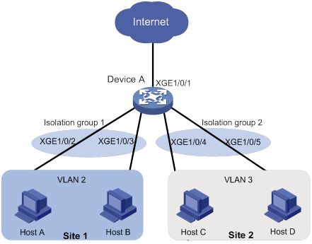
Network configuration
As shown in Figure 1, the company branches Site 1 and Site 2 transfer service traffic in VLAN 2 and VLAN 3. Device A connects to the Internet through Ten-GigabitEthernet 1/0/1.
Configure port isolation on Device A to meet the following requirements:
· All hosts can access the Internet through Device A.
· Host A and Host B are isolated from each other at Layer 2.
· Host C and Host D are isolated from each other at Layer 2.
Applicable hardware and software versions
The following matrix shows the hardware and software versions to which this configuration example is applicable:
|
Hardware |
Software version |
|
S6800 switch series S6860 switch series S6861 switch series |
Release 2702 |
Restrictions and guidelines
When you configure port isolation on the device, follow these restrictions and guidelines:
· Before assigning a port to an isolation group, make sure the isolation group already exists.
· You can assign a port to only one isolation group.
Procedures
# Create VLAN 2 and assign ports Ten-GigabitEthernet 1/0/2 and Ten-GigabitEthernet 1/0/3 to the VLAN.
<DeviceA> system-view
[DeviceA] vlan 2
[DeviceA-vlan2] port ten-gigabitethernet 1/0/2
[DeviceA-vlan2] port ten-gigabitethernet 1/0/3
[DeviceA-vlan2] quit
# Create VLAN 3 and assign ports Ten-GigabitEthernet 1/0/4 and Ten-GigabitEthernet 1/0/5 to the VLAN.
[DeviceA] vlan 3
[DeviceA-vlan3] port ten-gigabitethernet 1/0/4
[DeviceA-vlan3] port ten-gigabitethernet 1/0/5
[DeviceA-vlan3] quit
# Configure port Ten-GigabitEthernet 1/0/1 as a trunk port and assign it to VLAN 2 and VLAN 3.
[DeviceA] interface ten-gigabitethernet 1/0/1
[DeviceA-Ten-GigabitEthernet1/0/1] port link-type trunk
[DeviceA-Ten-GigabitEthernet1/0/1] port trunk permit vlan 2 3
[DeviceA-Ten-GigabitEthernet1/0/1] quit
# Create isolation groups 1 and 2.
[DeviceA] port-isolate group 1
[DeviceA] port-isolate group 2
# Assign ports Ten-GigabitEthernet 1/0/2 and Ten-GigabitEthernet 1/0/3 to isolation group 1.
[DeviceA] interface ten-gigabitethernet 1/0/2
[DeviceA-Ten-GigabitEthernet1/0/2] port-isolate enable group 1
[DeviceA-Ten-GigabitEthernet1/0/2] quit
[DeviceA] interface ten-gigabitethernet 1/0/3
[DeviceA-Ten-GigabitEthernet1/0/3] port-isolate enable group 1
[DeviceA-Ten-GigabitEthernet1/0/3] quit
# Assign ports Ten-GigabitEthernet 1/0/4 and Ten-GigabitEthernet 1/0/5 to isolation group 2.
[DeviceA] interface ten-gigabitethernet 1/0/4
[DeviceA-Ten-GigabitEthernet1/0/4] port-isolate enable group 2
[DeviceA-Ten-GigabitEthernet1/0/4] quit
[DeviceA] interface ten-gigabitethernet 1/0/5
[DeviceA-Ten-GigabitEthernet1/0/5] port-isolate enable group 2
[DeviceA-Ten-GigabitEthernet1/0/5] quit
Verifying the configuration
# Display information about all isolation groups.
[DeviceA] display port-isolate group
Port isolation group information:
Group ID: 1
Group members:
Ten-GigabitEthernet1/0/2
Ten-GigabitEthernet1/0/3
Group ID: 2
Group members:
Ten-GigabitEthernet1/0/4
Ten-GigabitEthernet1/0/5
The output shows that:
· Ports Ten-GigabitEthernet 1/0/2 and Ten-GigabitEthernet 1/0/3 are in isolation group 1. As a result, Host A and Host B are isolated from each other at Layer 2.
· Ports Ten-GigabitEthernet 1/0/4 and Ten-GigabitEthernet 1/0/4 are in isolation group 2. As a result, Host C and Host D are isolated from each other at Layer 2.
Configuration files
port-isolate group 1
port-isolate group 2
#
vlan 2 to 3
#
interface Ten-GigabitEthernet1/0/1
port link-mode bridge
port link-type trunk
port trunk permit vlan 1 to 3
#
interface Ten-GigabitEthernet1/0/2
port link-mode bridge
port access vlan 2
port-isolate enable group 1
#
interface Ten-GigabitEthernet1/0/3
port link-mode bridge
port access vlan 2
port-isolate enable group 1
#
interface Ten-GigabitEthernet1/0/4
port link-mode bridge
port access vlan 3
port-isolate enable group 2
#
interface Ten-GigabitEthernet1/0/5
port link-mode bridge
port access vlan 3
port-isolate enable group 2
#
Related documentation
· H3C S6800[S6860][S6861] (R27xx) & S6820 (R630x) Switch Series Layer 2—LAN Switching Configuration Guide
· H3C S6800[S6860][S6861] (R27xx) & S6820 (R630x) Switch Series Layer 2—LAN Switching Command Reference