- Table of Contents
-
- 01-Fundamentals Configuration Guide
- 00-Preface
- 01-CLI configuration
- 02-Login management configuration
- 03-RBAC configuration
- 04-FTP and TFTP configuration
- 05-File system management configuration
- 06-Configuration file management configuration
- 07-Software upgrade configuration
- 08-ISSU configuration
- 09-Device management configuration
- 10-Python configuration
- 11-License management(HP不支持)
- 12-Preprovisioning feature configuration
- 13-Automatic configuration
- Related Documents
-
| Title | Size | Download |
|---|---|---|
| 13-Automatic configuration | 110.13 KB |
Contents
Understanding automatic configuration
Overall automatic configuration process
Automatic-configuration parameter acquisition process
Configuration file acquisition process
Deploying and configuring servers for automatic configuration
DHCP server configuration guidelines
HTTP server configuration guidelines
TFTP server configuration guidelines
Using automatic configuration
With the automatic configuration feature, the device can automatically obtain a set of configuration settings from some servers when it starts up without a configuration file. This feature simplifies network configuration, facilitates centralized management, and reduces maintenance workload.
Understanding automatic configuration
The automatic configuration feature requires the cooperation of the following servers: a DHCP server, an HTTP server, a TFTP server, and a DNS server, as shown in Figure 1.
Figure 1 Typical automatic configuration network diagram
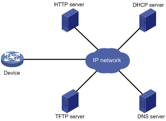
When the device is powered on without a configuration file, it automatically starts the automatic configuration process to try to obtain a set of configuration settings. If one attempt fails, the device waits 30 seconds, and then automatically starts the process again for another try. The device continues to make attempts until it obtains a set of configuration settings. To stop the process, power off the device or press Ctrl+D.
Overall automatic configuration process
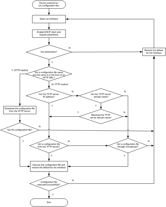
As shown in Figure 2, the automatic configuration process includes the following steps:
1. The device selects an interface for automatic configuration. For more information, see "Interface selection process."
2. After finding an interface, the device enables the DHCP client on the interface and tries to obtain a set of parameters for automatic configuration, which might include a temporary IP address, a configuration file name, a TFTP server domain name, a TFTP server IP address, and a DNS server IP address. For more information, see "Automatic-configuration parameter acquisition process."
3. After obtaining automatic configuration parameters, the device tries to download a configuration file from a TFTP server or an HTTP server. For more information, see "Configuration file acquisition process."
4. If the device obtains a configuration file, it deletes its temporary settings to restore the factory defaults and executes the configuration file. If the device does not obtain a configuration file or fails to execute the configuration file, it deletes its temporary settings and stays quiet for 30 seconds. Then, the device tries again for automatic configuration by selecting another qualified interface and repeating Step 2 to Step 4. To stop the automatic configuration process, press Ctrl+D at the CLI of the device.
|
|
IMPORTANT: · To ensure quick and successful automatic configuration of a device, connect only the interface used for automatic configuration to the network. · Make sure the configuration file does not contain commands for configuring the interface used for automatic configuration. Settings configured by the commands do not take effect. · Make sure the settings in the configuration file do not conflict with the running configuration for the interface used for automatic configuration. If conflicts exist, the device does not execute the relevant commands in the configuration file. For example, the configuration file cannot contain a command that assigns an interface an IP address that is on the same subnet as the interface used for automatic configuration. The device does not execute the command. · The device does not execute the port breakout configuration commands (if any) in the obtained configuration file. To make the port breakout configuration commands take effect, you must specify the configuration file as the next-startup configuration file and reboot the device. · The device does not save the obtained configuration file. To use the configuration after a reboot, save the running configuration by using the save command. Otherwise, the device has to perform automatic configuration again after a reboot. For more information about the save command, see Fundamentals Command Reference. |
Figure 2 Automatic configuration workflow
Interface selection process
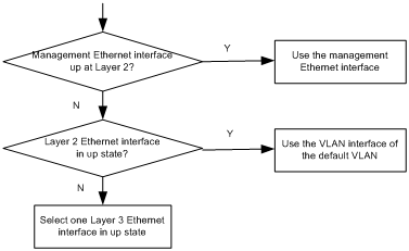
The device follows the following process to select an interface for automatic configuration:
1. If the device has a management Ethernet interface that is up at Layer 2, the device uses the management Ethernet interface for automatic configuration.
2. If the device has no management Ethernet interface in up state at Layer 2 but has Layer 2 Ethernet interfaces in up state, the device selects the VLAN interface of the default VLAN.
3. If no Layer 2 Ethernet interface is in up state, the device sorts all Layer 3 Ethernet interfaces in up state first by the dictionary order of the interface types and then in ascending order of interface numbers, and selects the one with the smallest interface number among the interfaces of the first interface type.
Figure 3 Interface selection process
Automatic-configuration parameter acquisition process
After the device finds an interface for automatic configuration, it enables the DHCP client on the interface. Then, the DHCP client broadcasts a DHCP request to locate a DHCP server and request configuration settings. The DHCP request uses DHCP Option 55 to indicate the configuration settings the device requires, including the configuration file name, the TFTP server domain name, the TFTP server IP address, and the DNS server IP address.
After receiving a DHCP reply, the device resolves the packet for the assigned IP address. If the reply provides an IP address, the device continues to examine the following options or fields in the DHCP reply:
· Option 67 or the file field—Carries the configuration file name. The device resolves Option 67 first. If Option 67 does not contain the configuration file name, the device resolves the file field. The configuration file name might indicate a file on an HTTP server or a TFTP server.
· Option 150—Carries the TFTP server IP address. If this option contains a valid TFTP server IP address, the device starts the configuration file acquisition process. Otherwise, the device resolves Option 66.
· Option 66—Carries the TFTP server domain name. If Option 150 does not contain a TFTP server IP address, the device resolves this option for a TFTP server domain name and tries to communicate with the DNS server indicated by Option 6 to obtain the TFTP server IP address.
· Option 6—Carries the DNS server IP address.
For more information about DHCP, see Layer 3—IP Services Configuration Guide.
Configuration file acquisition process
The device requests a configuration file from an HTTP server or a TFTP server:
· If the device got a configuration file name during the automatic-configuration parameter acquisition process, the device examines the form of the configuration file name. If the configuration file name is in the form of a valid HTTP URL, the device tries to download the configuration file from the URL. See Figure 2.
· If the device did not obtain a configuration file name during the automatic-configuration parameter acquisition process, or if the device got a configuration file name that is not in the form of a valid HTTP URL, the device starts to acquire a configuration file from a TFTP server:
? If the device has got a TFTP server IP address, it unicasts a request to the TFTP server.
? If it has not, the device broadcasts a request. In this case, the device resolves only the first reply.
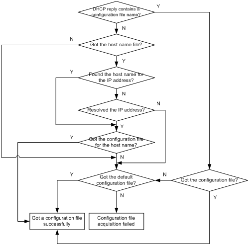
As shown in Figure 4, the device determines what to request from the TFTP server based on whether or not it got a configuration file name during the automatic-configuration parameter acquisition process:
? If the device got a configuration file name, it requests the specified configuration file.
? If not, it requests a configuration file named in the host name.cfg format from the TFTP server, where host name represents the host name of the device. To do so, the device first requests the host name file network.cfg, which contains mappings between IP addresses and host names. If the device fails to obtain the host name file or the file contains no entry for the device's temporary IP address, it tries to communicate with a DNS server to resolve the temporary IP address to a host name. After the device obtains the host name, it tries to obtain the configuration file for the host name.
If the device fails to obtain a configuration file specific for itself, it requests the default configuration file device.cfg from the TFTP server.
Figure 4 Configuration file acquisition process
Deploying and configuring servers for automatic configuration
To implement automatic configuration, you do not need to perform any configuration on the device. However, you must deploy DHCP, TFTP, and DNS servers and configure the servers to cooperate with the device as follows:
· DHCP server—Assigns the device a set of parameters for automatic configuration, which might include a temporary IP address, a configuration file name, a TFTP server domain name, a TFTP server IP address, and a DNS server IP address. For more information about the DHCP server, see Layer 3—IP Services Configuration Guide.
· HTTP server—Assigns files for automatic configuration to the device, for example, the configuration file.
· TFTP server—Stores files required for device automatic configuration, including the configuration files and host name files. For more information about the TFTP server, see "Configuring TFTP."
· DNS server—Resolves the device's temporary IP address to its host name so the device can request a configuration file named in the host name.cfg format from the TFTP server. The DNS server might also need to resolve the TFTP server domain name to the TFTP server IP address. For more information about the DNS server, see Layer 3—IP Services Configuration Guide.
If the DHCP server, the HTTP server, the TFTP server, the DNS server, and the device are not in the same network segment, configure the DHCP relay agent on the gateway, and configure routing protocols to make sure the servers have routes to the device and vice versa.
A configuration file for automatic configuration can be in the form of a Python script. A Python script can be used to implement automatic version update or configuration assignment. For more information about Python scripts, see "Using Python."
For successful automatic configuration, make sure a Python script for automatic configuration does not contain the fips mode enable command.
DHCP server configuration guidelines
When configuring the DHCP server, follow these guidelines:
· To make a device request a configuration file from an HTTP server, specify the HTTP URL of the configuration file. To make a device request a configuration file from a TFTP server, specify the path of the file in the working directory and the file name.
· If the devices on a network segment share the same configuration file, configure the dynamic address allocation mechanism on the connected interface of the DHCP server.
· If the devices on a network segment share most of their configurations, configure the dynamic address allocation mechanism on the connected interface of the DHCP server. You can put the configurations that the devices share to the configuration file, and provide a method for the device administrators to change the configurations after their devices start up. For example, you can use a configuration file to enable the Telnet service and create a local user, so administrators can Telnet to their devices to perform specific configurations after their devices start up.
· If the devices on a network segment require different configurations, configure the static address allocation mechanism on the connected interface of the DHCP server. This method allows you to have a separate configuration file for each device.
Before you configure a static binding for a device, you must obtain the client ID of the device. To obtain the client ID of a device, follow these steps:
a. Configure dynamic address allocation on the DHCP server's interface that is connected to the client.
b. Ask the device administrator to power on the device.
c. Execute the display dhcp server ip-in-use command on the DHCP server to view the client ID of the device after the device starts up.
After you complete the static binding configuration, ask the device administrator to power off the device and then power it on so the device obtains the IP address and configuration parameters you configured for it.
HTTP server configuration guidelines
Create configuration files required for device automatic configuration on the HTTP server. For easy file name identification, use configuration file names that do not contain spaces.
TFTP server configuration guidelines
Create configuration files and host name files required for device automatic configuration on the TFTP server, including the default configuration file device.cfg. For easy file name identification, use configuration file names that do not contain spaces.
To use the host name file network.cfg, create a configuration file for each device on the TFTP server, name the file in the host name.cfg format, and add a mapping entry in the ip host host-name ip-address format for the host name file. For example:
ip host host1 101.101.101.101
ip host host2 101.101.101.102
ip host client1 101.101.101.103
ip host client2 101.101.101.104
If a device resides in a network different than the TFTP server, configure the UDP helper feature on the gateway so the gateway changes the broadcast TFTP request from the device to a unicast packet and forwards the unicast packet to the TFTP server. For more information about UDP helper, see Layer 3—IP Services Configuration Guide.
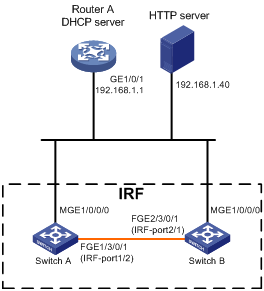
Automatic IRF setup example
Network requirements
As shown in Figure 5, Switch A and Switch B do not have a configuration file.
Configure the servers so the switches can obtain a Python script to complete their respective configurations and form an IRF fabric.
Configuration procedure
1. Assign IP addresses to the interfaces. Make sure the devices can reach each other. (Details not shown.)
2. Configure the following files on the HTTP server:
|
File |
Content |
Remarks |
|
.cfg configuration file |
Commands required for IRF setup. |
You can create a configuration file by modifying the configuration file exported from an existing IRF fabric. For more information, see IRF configuration in Virtual Technologies Configuration Guide. |
|
sn.txt |
Serial numbers of the member switches. |
Each SN uniquely identifies a switch. These SNs will be used for assigning a unique IRF member ID to each member switch. |
|
(Optional.) .ipe or .bin software image file |
Software images. |
If the member switches are running different software versions, you must prepare the software image file used for software upgrade. |
|
.py Python script files |
Python commands and APIs that complete the following tasks: a (Optional.) Verifies that the flash memory has sufficient space for the files to be downloaded. b Downloads the configuration file, sn.txt, and the software image file. c Sets the software image file as the main startup image file. d Assigns a unique IRF member ID to each SN. e Sets the configuration file as the main next-startup configuration file. f Reboots the member switches. |
Create a Python script file for each member switch. For more information about Python script configuration, see "Using Python." |
3. Configure the DHCP server:
# Enable DHCP.
<RouterA> system-view
[RouterA] dhcp enable
# Configure the address pool 1 to assign IP addresses on subnet 192.168.1.0/24 to clients.
[RouterA] dhcp server ip-pool 1
[RouterA-dhcp-pool-1] network 192.168.1.0 24
# Specify the URL of the script file for the clients.
[RouterA-dhcp-pool-1] bootfile-name http://192.168.1.40/device.py
4. Power on Switch A and Switch B.
Switch A and Switch B will obtain a Python script file from the DHCP server and execute the script. Then, Switch A and Switch B will reboot.
5. After Switch A and Switch B start up again, use a cable to connect Switch A and Switch B through their IRF physical ports.
Switch A and Switch B will elect a master. The subordinate will reboot to join the IRF fabric.
Verifying the configuration
# Display IRF fabric information.
<Switch A>display irf
MemberID Slot Role Priority CPU-Mac Description
1 1 Standby 1 00e0-fc0f-8c02 ---
*+2 1 Master 30 00e0-fc0f-8c14 ---
--------------------------------------------------
* indicates the device is the master.
+ indicates the device through which the user logs in.
The Bridge MAC of the IRF is: 000c-1000-1111
Auto upgrade : yes
Mac persistent : always
Domain ID : 0
Auto merge : yes
The output shows that the switches have formed an IRF fabric.