- Table of Contents
-
- 01-Fundamentals Configuration Guide
- 00-Preface
- 01-CLI configuration
- 02-Login management configuration
- 03-RBAC configuration
- 04-FTP and TFTP configuration
- 05-File system management configuration
- 06-Configuration file management configuration
- 07-Software upgrade configuration
- 08-ISSU configuration
- 09-Device management configuration
- 10-Python configuration
- 11-License management(HP不支持)
- 12-Preprovisioning feature configuration
- 13-Automatic configuration
- Related Documents
-
| Title | Size | Download |
|---|---|---|
| 02-Login management configuration | 365.45 KB |
Contents
Logging in through the console port for the first device access
Logging in through the console port locally
Disabling authentication for console login
Configuring password authentication for console login
Configuring scheme authentication for console login
Configuring common AUX line settings
Configuring Telnet login on the device
Using the device to log in to a Telnet server
Configuring the device as an SSH server
Using the device to log in to an SSH server
Displaying and maintaining CLI login
Accessing the device through SNMP
Configuring SNMPv1 or SNMPv2c access
Controlling Telnet and SSH logins
Configuring command authorization
Configuring command accounting
Login overview
The first time you access the device, you can log in to the CLI of the device through the console port. After login, you can change console login parameters, or configure other access methods, including Telnet, SSH, and SNMP.
The device supports the FIPS mode that complies with NIST FIPS 140-2 requirements. Support for features, commands, and parameters might differ in FIPS mode and non-FIPS mode. For more information about FIPS mode, see Security Configuration Guide.
Telnet login is not supported in FIPS mode.
Table 1 Login methods at a glance
|
Login method |
Default settings and minimum configuration requirements |
|
|
|
||
|
By default, login through the console port is enabled, no username or password is required, and the user role network-admin is assigned. After login, configure password or scheme authentication mode to improve device security. |
||
|
By default, Telnet login is disabled. To Log in through Telnet, complete the following configuration tasks: · Enable the Telnet server feature. · Assign an IP address to a Layer 3 interface and make sure the interface and the Telnet client can reach each other. · Configure an authentication mode for VTY login users. By default, password authentication is used but no password is configured. · Assign a user role to VTY login users. By default, a VTY login user is assigned the network-operator user role. |
||
|
By default, SSH login is disabled. To log in through SSH, complete the following configuration tasks: · Enable the SSH server feature and configure SSH attributes. · Assign an IP address to a Layer 3 interface and make sure the interface and the SSH client can reach each other. · Configure scheme authentication for VTY login users. By default, password authentication is used. · Assign a user role to VTY login users. By default, a VTY login user is assigned the network-operator user role. |
||
|
By default, SNMP access is disabled. To access the device through SNMP, complete the following configuration tasks: · Assign an IP address to a Layer 3 interface, and make sure the interface and the NMS can reach each other. · Configure SNMP basic parameters. |
||
Logging in through the console port for the first device access
The first time you access the device, you can only log in to the CLI through the console port.
To log in through the console port:
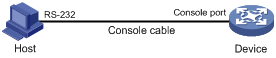
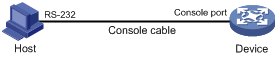
1. Connect the DB-9 female connector of the console cable to the serial port of the PC.
2. Connect the RJ-45 connector of the console cable to the console port of the device.
|
|
IMPORTANT: · Identify the mark on the console port and make sure you are connecting to the correct port. · The serial ports on PCs do not support hot swapping. If the switch has been powered on, always connect the console cable to the PC before connecting it to the switch, and always disconnect the console cable from the switch before disconnecting it from the PC. |
Figure 1 Connecting a terminal to the console port
3. If the PC is off, turn on the PC.
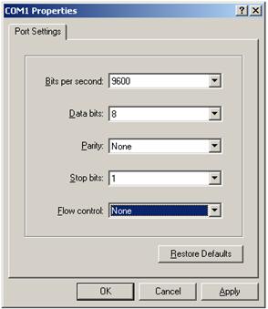
4. On the PC, launch the terminal emulation program and create a connection that uses the serial port connected to the device. Set the port properties so the port properties match the following console port default settings:
¡ Bits per second—9600 bps
¡ Flow control—None
¡ Parity—None
¡ Stop bits—1
¡ Data bits—8
Figure 2 through Figure 4 show the configuration procedure on Windows XP HyperTerminal. On Windows Server 2003, you must add the HyperTerminal program first. On Windows Server 2008, Windows 7, Windows Vista, or another operating system, you must obtain and install a third-party terminal control program and follow the user guide or online help to log in to the device.
To start the HyperTerminal on Windows XP:
a. Click start.
b. Select All Programs > Accessories > Communications > Hyper Terminal.
To view the serial port connected to the device:
a. Right-click the My Computer icon on the desktop.
b. Select Manage to open the Computer Management window.
c. Select System Tools > Device Manager from the navigation tree.
d. Select Ports (COM & LPT) from the right pane.
Figure 2 Creating a connection
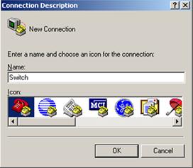
Figure 3 Specifying the serial port used to establish the connection
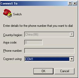
Figure 4 Setting the properties of the serial port
5. Power on the device and press Enter as prompted.
6. At the default user view prompt <H3C>, enter commands to configure the device or to view the running status of the device. To get help, enter ?.
Logging in to the CLI
By default, you can log in to the CLI through the console port. After you log in, you can configure other login methods, including Telnet, and SSH.
To prevent illegal access to the CLI and control user behavior, you can configure login authentication, assign user roles, configure command authorization and command accounting, and use ACLs to filter unauthorized logins.
This chapter describes how to configure and use CLI login methods, including login authentication, user roles, and common user line settings. For more information about command authorization, command accounting, and unauthorized access filtering, see "Controlling user access."
CLI overview
User lines
The device uses user lines (also called "user interfaces") to manage CLI sessions and monitor user behavior. You can configure access control settings, including login authentication and user role, on user lines. After users are logged in, their actions must be compliant with the settings on the user lines assigned to them.
Users are assigned different user lines, depending on their login methods, as shown in Table 2.
Table 2 CLI login method and user line matrix
|
User line |
Login method |
|
AUX line |
Console port. |
|
Virtual type terminal (VTY) line |
Telnet or SSH. |
User line assignment
The device automatically assigns user lines to CLI login users, depending on their login methods. Each user line can be assigned only to one user at a time. If no user line is available, a CLI login attempt will be rejected.
For a CLI login, the device always picks the lowest numbered user line from the idle user lines available for the login type. For example, four VTY lines (0 to 3) are configured, of which VTY 0 and VTY 3 are idle. When a user Telnets to the device, the device assigns VTY 0 to the user and uses the settings on VTY 0 to authenticate and manage the user.
User line identification
Every user line has an absolute number and a relative number for identification.
An absolute number uniquely identifies a user line among all user lines. The user lines are numbered starting from 0 and incrementing by 1 and in the sequence of AUX and VTY lines. You can use the display line command without any parameters to view supported user lines and their absolute numbers.
A relative number uniquely identifies a user line among all user lines that are the same type. The number format is user line type + number. Both the types of user lines are numbered starting from 0 and incrementing by 1. For example, the first VTY line is VTY 0.
Login authentication modes
You can configure login authentication to prevent illegal access to the device CLI.
In non-FIPS mode, the device supports the following login authentication modes:
· None—Disables authentication. This mode allows access without authentication and is insecure.
· Password—Requires password authentication.
· Scheme—Uses the AAA module to provide local or remote login authentication. You must provide a username and password at login.
In FIPS mode, the device supports only the scheme authentication mode.
Different login authentication modes require different user line configurations, as shown in Table 3.
Table 3 Configuration required for different login authentication modes
|
Authentication mode |
Configuration tasks |
|
|
None |
Set the authentication mode to none. |
|
|
Password |
1. Set the authentication mode to password. 2. Set a password. |
|
|
Scheme |
1. Set the authentication mode to scheme. 2. Configure login authentication methods in ISP domain view. For more information, see Security Configuration Guide. |
|
User roles
A user is assigned one or more user roles at login, and a user can access only commands permitted by the assigned user roles. For more information about user roles, see "Configuring RBAC."
The device assigns user roles based on the login authentication mode and login method:
· If none or password authentication is used, the device assigns user roles according to the user role configuration made on the user line.
· If scheme authentication is used:
¡ For an SSH login user who uses publickey or password-publickey authentication, the device assigns user roles according to the user role configuration made for the user in local user view.
¡ For other users, the device assigns user roles according to the user role configuration made on the AAA module. For remote AAA authentication users, if the AAA server does not assign any user role to a user and the default user role feature is disabled, the user cannot log in.
FIPS compliance
The device supports the FIPS mode that complies with NIST FIPS 140-2 requirements. Support for features, commands, and parameters might differ in FIPS mode and non-FIPS mode. For more information about FIPS mode, see Security Configuration Guide.
Telnet login is not supported in FIPS mode.
Logging in through the console port locally
You can connect a terminal to the console port of the device to log in and manage the device, as shown in Figure 5. For the login procedure, see "Logging in through the console port for the first device access."
Figure 5 Logging in through the console port
By default, console login is enabled and does not require authentication. To improve device security, configure the password or scheme authentication mode and assign user roles immediately after you log in to the device for the first time.
To configure console login, complete the following tasks:
|
Task |
Remarks |
|
(Required.) Configuring login authentication: · Disabling authentication for console login |
Configure one authentication mode as required. In FIPS mode, only the scheme authentication mode is supported. |
|
(Optional.) Configuring common AUX line settings |
N/A |
The console login configuration is effective only for users who log in after the configuration is completed.
Disabling authentication for console login
|
Step |
Command |
Remarks |
|
1. Enter system view. |
system-view |
N/A |
|
2. Enter AUX line view or class view. |
·
To enter AUX line view: ·
To enter AUX line class view: |
Use either command. A setting in user line view is applied only to the user line. A setting in user line class view is applied to all user lines of the class. A non-default setting in either view takes precedence over a default setting in the other view. A non-default setting in user line view takes precedence over a non-default setting in user line class view. A setting in user line view takes effect immediately and affects the online user. A setting in user line class view does not affect online users and takes effect only for users who log in after the configuration is completed. |
|
3. Disable authentication. |
authentication-mode none |
By default, authentication is disabled for the AUX line. |
|
4. Assign a user role. |
user-role role-name |
By default, an AUX line user is assigned the user role network-admin. |
The next time you attempt to log in through the console port, you do not need to provide any username or password.
Configuring password authentication for console login
|
Step |
Command |
Remarks |
|
1. Enter system view. |
system-view |
N/A |
|
2. Enter AUX line view or class view. |
·
To enter AUX line view: ·
To enter AUX line class view: |
Use either command. A setting in user line view is applied only to the user line. A setting in user line class view is applied to all user lines of the class. A non-default setting in either view takes precedence over a default setting in the other view. A non-default setting in user line view takes precedence over a non-default setting in user line class view. A setting in user line view takes effect immediately and affects the online user. A setting in user line class view does not affect online users and takes effect only for users who log in after the configuration is completed. |
|
3. Enable password authentication. |
authentication-mode password |
By default, authentication is disabled for the AUX line. |
|
4. Set a password. |
set authentication password { hash | simple } password |
By default, no password is set. |
|
5. Assign a user role. |
user-role role-name |
By default, an AUX line user is assigned the user role network-admin. |
The next time you attempt to log in through the console port, you must provide the configured login password.
Configuring scheme authentication for console login
|
Step |
Command |
Remarks |
|
1. Enter system view. |
system-view |
N/A |
|
2. Enter AUX line view or class view. |
·
To enter AUX line view: ·
To enter AUX line class view: |
Use either command. A setting in user line view is applied only to the user line. A setting in user line class view is applied to all user lines of the class. A non-default setting in either view takes precedence over a default setting in the other view. A non-default setting in user line view takes precedence over a non-default setting in user line class view. A setting in user line view takes effect immediately and affects the online user. A setting in user line class view does not affect online users and takes effect only for users who log in after the configuration is completed. |
|
3. Enable scheme authentication. |
authentication-mode scheme |
By default, authentication is disabled for the AUX line. |
To use scheme authentication, you must also configure login authentication methods in ISP domain view:
· To use local authentication, you must create a local user and configure local user attributes on the device.
· To use remote authentication, you must configure a scheme on the device and configure the remote server.
For more information, see Security Configuration Guide.
The next time you attempt to log in through the console port, you must provide the configured login username and password.
Configuring common AUX line settings
Some common settings configured for an AUX line take effect immediately and can interrupt the current session. Use a login method different from console login to log in to the device before you change AUX line settings.
To log in through the console port after the configuration is completed, change the terminal settings on the configuration terminal to match the console port settings on the device.
To configure common settings for an AUX line:
|
Step |
Command |
|
|
N/A |
||
|
2. Enter AUX line view or class view. |
·
To enter AUX line view: ·
To enter AUX line class view: |
Use either command. A setting in user line view is applied only to the user line. A setting in user line class view is applied to all user lines of the class. A non-default setting in either view takes precedence over a default setting in the other view. A non-default setting in user line view takes precedence over a non-default setting in user line class view. A setting in user line view takes effect immediately and affects the online user. A setting in user line class view does not affect online users and takes effect only for users who log in after the configuration is completed. |
|
3. Set the baud rate. |
speed speed-value |
By default, the baud rate is 9600 bps. This command is not available in AUX line class view. |
|
4. Specify the parity check mode. |
parity { even | mark | none | odd | space } |
By default, the parity check mode is none, and no parity check is performed. This command is not available in AUX line class view. |
|
5. Specify the number of stop bits. |
stopbits { 1 | 1.5 | 2 } |
The default is 1. Stop bits indicate the end of a character. The more the stop bits, the slower the transmission. This command is not available in AUX line class view. |
|
6. Specify the number of data bits for each character. |
databits { 5 | 6 | 7 | 8 } |
The default is 8. The setting depends on the character coding type. For example, you can set it to 7 if standard ASCII characters are to be sent, and set it to 8 if extended ASCII characters are to be sent. This command is not available in AUX line class view. |
|
7. Define a shortcut key for starting a terminal session. |
activation-key character |
|
|
8. Define a shortcut key for terminating tasks. |
escape-key { character | default } |
|
|
9. Configure the flow control mode. |
flow-control { hardware | none | software } |
By default, the flow control mode is none. This command is not available in AUX line class view. |
|
10. Specify the terminal display type. |
terminal type { ansi | vt100 } |
By default, the terminal display type is ANSI. The device supports ANSI and VT100 terminal display types. As a best practice, set the display type to VT100 on both the device and the configuration terminal. If either side uses the ANSI type, a display problem such as cursor positioning error might occur when a command line has more than 80 characters. |
|
11. Set the maximum number of lines to be displayed on a screen. |
screen-length screen-length |
By default, a screen displays 24 lines at most. |
|
12. Set the size of the command history buffer. |
history-command max-size value |
|
|
13. Set the CLI connection idle-timeout timer. |
idle-timeout minutes [ seconds ] |
By default, the CLI connection idle-timeout timer is 10 minutes. If no interaction occurs between the device and the user within the idle-timeout interval, the system automatically terminates the user connection on the user line. If you set the timeout timer to 0, the connection will not be aged out. |
Logging in through Telnet
You can Telnet to the device to remotely manage the device, or use the device as a Telnet client to Telnet to other devices to manage them.
By default, Telnet login is disabled on the device. To log in to the device through Telnet, you must first log in to the device through any other method, enable the Telnet server, and configure Telnet login authentication on the device.
|
|
NOTE: Telnet login is not supported in FIPS mode. For more information about FIPS mode, see Security Configuration Guide. |
Configuring Telnet login on the device
|
Task |
Remarks |
|
(Required.) Configuring login authentication: · Disabling authentication for Telnet login |
Configure one authentication mode as required. |
|
(Optional.) Setting the maximum number of concurrent Telnet users |
N/A |
|
(Optional.) Setting the DSCP value for outgoing Telnet packets |
N/A |
|
(Optional.) Configuring common VTY line settings |
N/A |
The Telnet login configuration is effective only for users who log in after the configuration is completed.
Disabling authentication for Telnet login
|
Step |
Command |
Remarks |
|
1. Enter system view. |
system-view |
N/A |
|
2. Enable Telnet server. |
telnet server enable |
By default, the Telnet server feature is disabled. |
|
3. Enter VTY line view or class view. |
·
To enter VTY line view: ·
To enter VTY line class view: |
Use either command. A setting in user line view is applied only to the user line. A setting in user line class view is applied to all user lines of the class. A non-default setting in either view takes precedence over a default setting in the other view. A non-default setting in user line view takes precedence over a non-default setting in user line class view. A setting in user line view takes effect immediately and affects the online user. A setting in user line class view does not affect online users and takes effect only for users who log in after the configuration is completed. |
|
4. Disable authentication. |
authentication-mode none |
By default, password authentication is enabled for VTY lines. In VTY line view, this command is associated with the protocol inbound command. If you specify a non-default value for only one of the two commands in VTY line view, the other command uses the default setting, regardless of the setting in VTY line class view. |
|
5. (Optional.) Assign a user role. |
user-role role-name |
By default, a VTY line user is assigned the user role network-operator. |
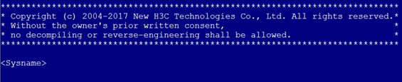
The next time you attempt to Telnet to the device, you do not need to provide any username or password, as shown in Figure 6. If the maximum number of login users has been reached, your login attempt fails and the message "All user lines are used, please try later!" appears.
Figure 6 Telnetting to the device without authentication
Configuring password authentication for Telnet login
|
Step |
Command |
Remarks |
|
1. Enter system view. |
system-view |
N/A |
|
2. Enable Telnet server. |
telnet server enable |
By default, the Telnet server feature is disabled. |
|
3. Enter VTY line view or class view. |
·
To enter VTY line view: ·
To enter VTY line class view: |
Use either command. A setting in user line view is applied only to the user line. A setting in user line class view is applied to all user lines of the class. A non-default setting in either view takes precedence over a default setting in the other view. A non-default setting in user line view takes precedence over a non-default setting in user line class view. A setting in user line view takes effect immediately and affects the online user. A setting in user line class view does not affect online users and takes effect only for users who log in after the configuration is completed. |
|
4. Enable password authentication. |
authentication-mode password |
By default, password authentication is enabled for VTY lines. In VTY line view, this command is associated with the protocol inbound command. If you specify a non-default value for only one of the two commands in VTY line view, the other command uses the default setting, regardless of the setting in VTY line class view. |
|
5. Set a password. |
set authentication password { hash | simple } password |
By default, no password is set. |
|
6. (Optional.) Assign a user role. |
user-role role-name |
By default, a VTY line user is assigned the user role network-operator. |
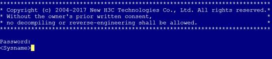
The next time you attempt to Telnet to the device, you must provide the configured login password, as shown in Figure 7. If the maximum number of login users has been reached, your login attempt fails and the message "All user lines are used, please try later!" appears.
Figure 7 Password authentication interface for Telnet login
Configuring scheme authentication for Telnet login
|
Step |
Command |
Remarks |
|
1. Enter system view. |
system-view |
N/A |
|
2. Enable Telnet server. |
telnet server enable |
By default, the Telnet server feature is disabled. |
|
3. Enter VTY line view or class view. |
·
To enter VTY line view: ·
To enter VTY line class view: |
Use either command. A setting in user line view is applied only to the user line. A setting in user line class view is applied to all user lines of the class. A non-default setting in either view takes precedence over a default setting in the other view. A non-default setting in user line view takes precedence over a non-default setting in user line class view. A setting in user line view takes effect immediately and affects the online user. A setting in user line class view does not affect online users and takes effect only for users who log in after the configuration is completed. |
|
4. Enable scheme authentication. |
authentication-mode scheme |
By default, password authentication is enabled for VTY lines. In VTY line view, this command is associated with the protocol inbound command. If you specify a non-default value for only one of the two commands in VTY line view, the other command uses the default setting, regardless of the setting in VTY line class view. |
To use scheme authentication, you must also configure login authentication methods in ISP domain view. For more information, see Security Configuration Guide.
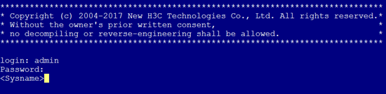
The next time you attempt to Telnet to the CLI, you must provide the configured login username and password, as shown in Figure 8. If the maximum number of login users has been reached, your login attempt fails and the message "All lines are used, please try later!" appears.
Figure 8 Scheme authentication interface for Telnet login
Setting the maximum number of concurrent Telnet users
|
Step |
Command |
Remarks |
|
1. Enter system view. |
system-view |
N/A |
|
2. Set the maximum number of concurrent Telnet users. |
aaa session-limit telnet max-sessions |
By default, the maximum number of concurrent Telnet users is 32. Changing this setting does not affect online users. If the current number of online Telnet users is equal to or greater than the new setting, no additional Telnet users can log in until online users log out. For more information about this command, see Security Command Reference. |
Setting the DSCP value for outgoing Telnet packets
The DSCP value is carried in the ToS/Traffic class field of an IP packet, and it indicates the transmission priority of the packet.
To set the DSCP value for outgoing Telnet packets:
|
Step |
Command |
Remarks |
|
1. Enter system view. |
system-view |
N/A |
|
2. Set the DSCP value for outgoing Telnet packets. |
·
For an IPv4 Telnet server: ·
For an IPv6 Telnet server: |
By default, the DSCP value is 48. |
Configuring common VTY line settings
For a VTY line, you can specify a command that is to be automatically executed when a user logs in. After executing the specified command, the system automatically disconnects the Telnet session. Typically, you configure the auto-execute command telnet X.X.X.X command on the device so the device redirects a Telnet user to the host at X.X.X.X. In this case, the connection to the current device is closed when the user terminates the Telnet connection to X.X.X.X.
To configure common settings for VTY lines:
|
Step |
Command |
Remarks |
|
1. Enter system view. |
system-view |
N/A |
|
2. Enter VTY line view or class view. |
·
To enter VTY line view: ·
To enter VTY line class view: |
Use either command. A setting in user line view is applied only to the user line. A setting in user line class view is applied to all user lines of the class. A non-default setting in either view takes precedence over a default setting in the other view. A non-default setting in user line view takes precedence over a non-default setting in user line class view. A setting in user line view takes effect immediately and affects the online user. A setting in user line class view does not affect online users and takes effect only for users who log in after the configuration is completed. |
|
3. Enable the terminal service. |
shell |
By default, terminal service is enabled. |
|
4. Specify the protocols for the user lines to support. |
protocol inbound { all | ssh | telnet } |
By default, both Telnet and SSH are supported. This configuration is effective only for users who log in to the user lines after the configuration is completed. In VTY line view, this command is associated with the authentication-mode command. If you specify a non-default value for only one of the two commands in VTY line view, the other command uses the default setting, regardless of the setting in VTY line class view. |
|
5. Define a shortcut key for terminating tasks. |
escape-key { character | default } |
By default, pressing Ctrl+C terminates a task. |
|
6. Specify the terminal display type. |
terminal type { ansi | vt100 } |
By default, the terminal display type is ANSI. |
|
7. Set the maximum number of lines to be displayed on a screen. |
screen-length screen-length |
By default, up to 24 lines is displayed on a screen. To disable pausing between screens of output, set the value to 0. |
|
8. Set the size of command history buffer. |
history-command max-size value |
By default, the buffer saves 10 history commands. |
|
9. Set the CLI connection idle-timeout timer. |
idle-timeout minutes [ seconds ] |
By default, the CLI connection idle-timeout timer is 10 minutes. If no interaction occurs between the device and the user within the idle-timeout interval, the system automatically terminates the user connection on the user line. If you set the timeout timer to 0, the connection will not be aged out. |
|
10. Specify the command to be automatically executed for login users on the user lines. |
auto-execute command command |
By default, no automatically executed command is specified.
Before you configure this command and save the configuration, make sure you can access the CLI through a different user line. |
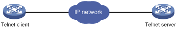
Using the device to log in to a Telnet server
You can use the device as a Telnet client to log in to a Telnet server. If the server is located in a different subnet than the device, make sure the two devices have routes to reach each other.
Figure 9 Telnetting from the device to a Telnet server
To use the device to log in to a Telnet server:
|
Step |
Command |
Remarks |
|
1. Enter system view. |
system-view |
N/A |
|
2. (Optional.) Specify the source IPv4 address or source interface for outgoing Telnet packets. |
telnet client source { interface interface-type interface-number | ip ip-address } |
By default, no source IPv4 address or source interface is specified, and the primary IPv4 address of the outbound interface is used as the source address for outgoing Telnet packets. |
|
3. Exit to user view. |
quit |
N/A |
|
4. Use the device to log in to a Telnet server. |
·
Log in to an IPv4 Telnet server: ·
Log in to an IPv6 Telnet server: |
This command is available in user view. |
Logging in through SSH
SSH offers a secure method to remote login. By providing encryption and strong authentication, it protects devices against attacks such as IP spoofing and plain text password interception. For more information, see Security Configuration Guide.
You can use an SSH client to log in to the device for remote management, or use the device as an SSH client to log in to an SSH server.
By default, SSH login is disabled on the device. To log in to the device through SSH, you must log in to the device through any other method and configure SSH login on the device first.
Configuring the device as an SSH server
This section provides the configuration procedure for when the SSH client authentication method is password. For more information about SSH and publickey authentication configuration, see Security Configuration Guide.
To configure SSH login on the device:
|
Step |
Command |
Remarks |
|
|
1. Enter system view. |
system-view |
N/A |
|
|
2. Create local key pairs. |
public-key local create { dsa | rsa | ecdsa } [ name key-name ] |
By default, no local key pairs are created. |
|
|
3. Enable SSH server. |
ssh server enable |
By default, SSH server is disabled. |
|
|
4. (Optional.) Create an SSH user and specify the authentication mode. |
·
In non-FIPS mode: ·
In FIPS mode: |
By default, no SSH user is configured on the device. |
|
|
5. Enter VTY line view or class view. |
·
To enter VTY line view: ·
To enter VTY line class view: |
Use either command. A setting in user line view is applied only to the user line. A setting in user line class view is applied to all user lines of the class. A non-default setting in either view takes precedence over a default setting in the other view. A non-default setting in user line view takes precedence over a non-default setting in user line class view. A setting in user line view takes effect immediately and affects the online user. A setting in user line class view does not affect online users and takes effect only for users who log in after the configuration is completed. |
|
|
6. Enable scheme authentication. |
authentication-mode scheme |
In non-FIPS mode, password authentication is enabled for VTY lines by default. In FIPS mode, scheme authentication is enabled for VTY lines by default. In VTY line view, this command is associated with the protocol inbound command. If you specify a non-default value for only one of the two commands in VTY line view, the other command uses the default setting, regardless of the setting in VTY line class view. |
|
|
7. (Optional.) Specify the protocols for the user lines to support. |
·
In non-FIPS mode: ·
In FIPS mode: |
In non-FIPS mode, both Telnet and SSH are supported by default. In FIPS mode, SSH is supported by default. This configuration takes effect only for users who log in to the user lines after the configuration is completed. In VTY line view, this command is associated with the authentication-mode command. If you specify a non-default value for only one of the two commands in VTY line view, the other command uses the default setting, regardless of the setting in VTY line class view. |
|
|
8. Set the maximum number of concurrent SSH users. |
aaa session-limit ssh max-sessions |
By default, the maximum number of concurrent SSH users is 32. Changing this setting does not affect online users. If the current number of online SSH users is equal to or greater than the new setting, no additional SSH users can log in until the online users log out. For more information about this command, see Security Command Reference. |
|
|
9. Exit to system view. |
quit |
N/A |
|
|
10. (Optional.) Configure common settings for VTY lines. |
N/A |
|
|
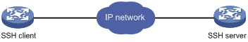
Using the device to log in to an SSH server
You can use the device as an SSH client to log in to an SSH server. If the server is located in a different subnet than the device, make sure the two devices have routes to reach each other.
Figure 10 Logging in to an SSH client from the device
Perform the following tasks in user view:
|
Task |
Command |
|
Log in to an IPv4 SSH server. |
ssh2 server |
|
Log in to an IPv6 SSH server. |
ssh2 ipv6 server |
To work with the SSH server, you might need to configure the SSH client. For information about configuring the SSH client, see Security Configuration Guide.
Displaying and maintaining CLI login
Execute display commands in any view and the other commands in user view.
|
Task |
Command |
Remarks |
|
Display online CLI user information. |
display users [ all ] |
N/A |
|
Display user line information. |
display line [ num1 | { aux | vty } num2 ] [ summary ] |
N/A |
|
Display the source IPv4 address or interface configured for the device to use for outgoing Telnet packets when serving as a Telnet client. |
display telnet client |
N/A |
|
Release a user line. |
free line { num1 | { aux | vty } num2 } |
Multiple users can log in to the device to simultaneously configure the device. When necessary, you can execute this command to release some connections. You cannot use this command to release the connection you are using. |
|
Lock the current user line. |
lock |
By default, the system does not lock any user line. This command is not supported in FIPS mode. |
|
Send messages to user lines. |
send { all | num1 | { aux | vty } num2 } |
This command is available in user view. |
Accessing the device through SNMP
You can run SNMP on an NMS to access the device MIB and perform Get and Set operations to manage and monitor the device.
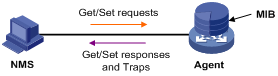
The device supports SNMPv1, SNMPv2c, and SNMPv3, and can work with various network management software products, including IMC. However, the device and the NMS must use the same SNMP version. For more information about SNMP, see Network Management and Monitoring Configuration Guide.
By default, SNMP access is disabled. To access the device through SNMP, you must log in to the device through any other method and configure SNMP access.
Configuring SNMPv3 access
|
Step |
Command |
Remarks |
|
1. Enter system view. |
system-view |
N/A |
|
2. Enable the SNMP agent. |
snmp-agent |
By default, the SNMP agent is disabled. |
|
3. (Optional.) Create or update MIB view information. |
snmp-agent mib-view { excluded | included } view-name oid-tree [ mask mask-value ] |
By default, the device has four views, all of which are named ViewDefault: · View 1 includes MIB subtree iso. · View 2 does not include subtree snmpUsmMIB. · View 3 does not include subtree snmpVacmMIB. · View 4 does not include subtree snmpModules.18. |
|
4. Create an SNMPv3 group. |
snmp-agent group v3 group-name [ authentication | privacy ] [ read-view view-name ] [ write-view view-name ] [ notify-view view-name ] [ acl acl-number ] * |
By default, no SNMPv3 group exists. |
|
5. Create an SNMPv3 user. |
snmp-agent usm-user v3 user-name group-name [ remote ip-address [ vpn-instance vpn-instance-name ] ] [ { cipher | simple } authentication-mode { md5 | sha } auth-password [ privacy-mode { aes128 | des56 } priv-password ] ] [ acl acl-number ] * |
To send informs to an SNMPv3 NMS, you must use the remote ip-address option to specify the IP address of the NMS. |
Configuring SNMPv1 or SNMPv2c access
|
Step |
Command |
Remarks |
|
1. Enter system view. |
system-view |
N/A |
|
2. Enable the SNMP agent. |
snmp-agent |
By default, the SNMP agent is disabled. |
|
3. (Optional.) Create or update MIB view information. |
snmp-agent mib-view { excluded | included } view-name oid-tree [ mask mask-value ] |
By default, the device has four views, all of which are named ViewDefault: · View 1 includes MIB subtree iso. · View 2 does not include subtree snmpUsmMIB. · View 3 does not include subtree snmpVacmMIB. · View 4 does not include subtree snmpModules.18. |
|
4. Configure the SNMP access right. |
·
(Method 1) Specify the SNMP NMS access right directly by configuring an
SNMP community: · (Method 2) Configure an SNMP group and add a user to the SNMP group: a. snmp-agent group { v1 | v2c } group-name [ read-view view-name ] [ write-view view-name ] [ notify-view view-name ] [ acl acl-number ] * b. snmp-agent usm-user { v1 | v2c } user-name group-name [ acl acl-number ] * |
Use either method. The username in method 2 is equivalent to the community name used in method 1, and must be the same as the community name configured on the NMS. By default, no SNMP group or SNMP community exists. |
Controlling user access
Use ACLs to prevent unauthorized access and configure command authorization and accounting to monitor and control user behavior. For more information about ACLs, see ACL and QoS Configuration Guide.
FIPS compliance
The device supports the FIPS mode that complies with NIST FIPS 140-2 requirements. Support for features, commands, and parameters might differ in FIPS mode and non-FIPS mode. For more information about FIPS mode, see Security Configuration Guide.
Telnet and HTTP are not supported in FIPS mode.
Controlling Telnet and SSH logins
Use basic ACLs (2000 to 2999) to filter Telnet and SSH logins by source IP address. Use advanced ACLs (3000 to 3999) to filter Telnet and SSH logins by source and/or destination IP address. Use Ethernet frame header ACLs (4000 to 4999) to filter Telnet and SSH logins by source MAC address.
If an applied ACL does not exist or has no rules, no user login restriction is applied. If the ACL exists and has rules, only users permitted by the ACL can access the device through Telnet or SSH.
Configuration procedures
|
Step |
Command |
Remarks |
|
1. Enter system view. |
system-view |
N/A |
|
Apply an ACL to filter Telnet logins. |
· telnet server acl acl-number · telnet server ipv6 acl [ ipv6 ] acl-number |
By default, no ACL is used to filter Telnet logins. |
To control SSH logins:
|
Step |
Command |
Remarks |
|
3. Enter system view. |
system-view |
N/A |
|
Apply an ACL to filter SSH logins. |
· ssh server acl acl-number · ssh server ipv6 acl [ ipv6 ] acl-number |
By default, no ACL is used to filter SSH logins. For more information, see Security Command Reference. |
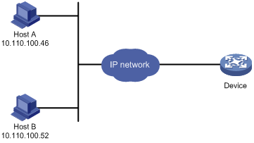
Configuration example
Network requirements
Configure the device in Figure 12 to permit only Telnet packets sourced from Host A and Host B.
Configuration procedure
# Configure an ACL to permit packets sourced from Host A and Host B.
<Sysname> system-view
[Sysname] acl number 2000 match-order config
[Sysname-acl-basic-2000] rule 1 permit source 10.110.100.52 0
[Sysname-acl-basic-2000] rule 2 permit source 10.110.100.46 0
[Sysname-acl-basic-2000] quit
# Apply the ACL to filter Telnet logins.
[Sysname] telnet server acl 2000
Controlling SNMP access
Use a basic ACL (2000 to 2999) to control SNMP access by source IP address. To access the requested MIB view, an NMS must use a source IP address permitted by the ACL.
Configuration procedure
To control SNMPv1 or SNMPv2c access:
|
Step |
Command |
Remarks |
|
1. Enter system view. |
system-view |
N/A |
|
2. Configure the SNMP access right. |
· (Method 1.) Create an SNMP community and specify ACLs for the community: ¡ In VACM
mode: ¡ In RBAC
mode: · (Method 2.) Create an SNMPv1/v2c group and add a user to the group, specifying ACLs for the group and user: a. snmp-agent group { v1 | v2c } group-name [ read-view view-name ] [ write-view view-name ] [ notify-view view-name ] [ acl acl-number | acl ipv6 ipv6-acl-number ] * b. snmp-agent usm-user { v1 | v2c } user-name group-name [ acl acl-number | acl ipv6 ipv6-acl-number ] * |
For more information about SNMP, see Network Management and Monitoring Configuration Guide. |
To control SNMPv3 access:
|
Step |
Command |
Remarks |
|
1. Enter system view. |
system-view |
N/A |
|
2. Create an SNMPv3 group, specifying ACLs for the group. |
·
In non-FIPS mode: · In FIPS mode: |
N/A |
|
3. Create an SNMPv3 user, specifying ACLs for the user. |
· In non-FIPS mode: ¡ In VACM mode: ¡ In RBAC mode: · In FIPS mode: ¡ In VACM mode: |
For more information about SNMP, see Network Management and Monitoring Configuration Guide. |
Configuration example
Network requirements
Configure the device in Figure 13 to allow Host A and Host B to access the device through SNMP.

Configuration procedure
# Create an ACL to permit packets sourced from Host A and Host B.
<Sysname> system-view
[Sysname] acl number 2000 match-order config
[Sysname-acl-basic-2000] rule 1 permit source 10.110.100.52 0
[Sysname-acl-basic-2000] rule 2 permit source 10.110.100.46 0
[Sysname-acl-basic-2000] quit
# Associate the ACL with the SNMP community and the SNMP group.
[Sysname] snmp-agent community read aaa acl 2000
[Sysname] snmp-agent group v2c groupa acl 2000
[Sysname] snmp-agent usm-user v2c usera groupa acl 2000
Configuring command authorization
By default, commands are available for a user depending only on that user's user roles. When the authentication mode is scheme, you can configure the command authorization feature to further control access to commands.
After you enable command authorization, a command is available for a user only if the user has the commensurate user role and is authorized to use the command by the AAA scheme.
This section provides the procedure for configuring command authorization. To make the command authorization feature take effect, you must configure a command authorization method in ISP domain view. For more information, see Security Configuration Guide.
Configuration procedure
To configure command authorization:
|
Step |
Command |
Remarks |
|
1. Enter system view. |
system-view |
N/A |
|
2. Enter user line view or user line class view. |
·
To enter user line view: ·
To enter user line class view: |
Use either command. A setting in user line view is applied only to the user line. A setting in user line class view is applied to all user lines of the class. A non-default setting in either view takes precedence over a default setting in the other view. A non-default setting in user line view takes precedence over a non-default setting in user line class view. A setting in user line view takes effect immediately and affects the online user. A setting in user line class view does not affect online users and takes effect only for users who log in after the configuration is completed. |
|
3. Enable scheme authentication. |
authentication-mode scheme |
By default, authentication is disabled for the AUX line and password authentication is enabled for the VTY line. In VTY line view, this command is associated with the protocol inbound command. If you specify a non-default value for only one of the two commands in VTY line view, the other command uses the default setting, regardless of the setting in VTY line class view. |
|
4. Enable command authorization. |
command authorization |
By default, command authorization is disabled. The commands available for a user only depend on the user role. If the command authorization command is configured in user line class view, command authorization is enabled on all user lines in the class, and you cannot configure the undo command authorization command in the view of a user line in the class. |
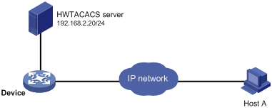
Configuration example
Network requirements
As shown in Figure 14, Host A needs to log in to the device to manage the device.
Configure the device to perform the following operations:
· Allow Host A to Telnet in after authentication.
· Use the HWTACACS server to control the commands that the user can execute.
· If the HWTACACS server is not available, use local authorization.
Configuration procedure
# Assign IP addresses to relevant interfaces and make sure the device and the HWTACACS server can reach each other and the device and Host A can reach each other. (Details not shown.)
# Enable the Telnet server.
<Device> system-view
[Device] telnet server enable
# Enable scheme authentication for user lines VTY 0 through VTY 63.
[Device] line vty 0 63
[Device-line-vty0-63] authentication-mode scheme
# Enable command authorization for the user lines.
[Device-line-vty0-63] command authorization
[Device-line-vty0-63] quit
# Configure an HWTACACS scheme that does the following:
· Uses the HWTACACS server at 192.168.2.20:49 for authentication and authorization. In this example, the HWTACACS server provides authentication and authorization services at port 49.
· Uses the shared key expert.
· Removes domain names from usernames sent to the HWTACACS server.
[Device] hwtacacs scheme tac
[Device-hwtacacs-tac] primary authentication 192.168.2.20 49
[Device-hwtacacs-tac] primary authorization 192.168.2.20 49
[Device-hwtacacs-tac] key authentication expert
[Device-hwtacacs-tac] key authorization expert
[Device-hwtacacs-tac] server-type standard
[Device-hwtacacs-tac] user-name-format without-domain
[Device-hwtacacs-tac] quit
# Configure the system-predefined domain system to use the HWTACACS scheme tac for login user authentication and command authorization and to use local authentication and local authorization as the backup method.
[Device] domain system
[Device-isp-system] authentication login hwtacacs-scheme tac local
[Device-isp-system] authorization command hwtacacs-scheme tac local
[Device-isp-system] quit
# Create local user monitor, set the password to 123, assign the Telnet service, and set the default user role to level-1.
[Device] local-user monitor
[Device-luser-manage-admin] password cipher 123
[Device-luser-manage-admin] service-type telnet
[Device-luser-manage-admin] authorization-attribute user-role level-1
Configuring command accounting
Command accounting allows the HWTACACS server to record all executed commands that are supported by the device, regardless of the command execution result. This feature helps control and monitor user behavior on the device.
When command accounting is disabled, the accounting server does not record the commands executed by users. If command accounting is enabled but command authorization is not, every executed command is recorded on the HWTACACS server. If both command accounting and command authorization are enabled, only authorized commands that are executed are recorded on the HWTACACS server.
This section provides only the procedure for configuring command accounting. To make the command accounting feature take effect, you must configure a command accounting method in ISP domain view. For more information, see Security Configuration Guide.
Configuration procedure
To configure command accounting:
|
Step |
Command |
Remarks |
|
1. Enter system view. |
system-view |
N/A |
|
2. Enter user line view or user line class view. |
·
To enter user line view: ·
To enter user line class view: |
Use either command. A setting in user line view is applied only to the user line. A setting in user line class view is applied to all user lines of the class. A non-default setting in either view takes precedence over a default setting in the other view. A non-default setting in user line view takes precedence over a non-default setting in user line class view. A setting in user line view takes effect immediately and affects the online user. A setting in user line class view does not affect online users and takes effect only for users who log in after the configuration is completed. |
|
3. Enable scheme authentication. |
authentication-mode scheme |
By default, authentication is disabled for the AUX line and password authentication is enabled for the VTY line. In VTY line view, this command is associated with the protocol inbound command. If you specify a non-default value for only one of the two commands in VTY line view, the other command uses the default setting, regardless of the setting in VTY line class view. |
|
4. Enable command accounting. |
command accounting |
By default, command accounting is disabled. The accounting server does not record the commands executed by users. If the command accounting command is configured in user line class view, command accounting is enabled on all user lines in the class. You cannot configure the undo command accounting command in the view of a user line in the class. |
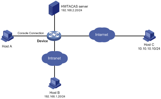
Configuration example
Network requirements
As shown in Figure 15, users need to log in to the device to manage the device.
Configure the device to send commands executed by users to the HWTACACS server to monitor and control user operations on the device.
Configuration procedure
# Enable the Telnet server.
<Device> system-view
[Device] telnet server enable
# Enable command accounting for user line AUX 0.
[Device] line aux 0
[Device-line-aux0] command accounting
[Device-line-aux0] quit
# Enable command accounting for user lines VTY 0 through VTY 63.
[Device] line vty 0 63
[Device-line-vty0-63] command accounting
[Device-line-vty0-63] quit
# Create HWTACACS scheme tac.
[Device] hwtacacs scheme tac
# Configure the scheme to use the HWTACACS server at 192.168.2.20:49 for accounting.
[Device-hwtacacs-tac] primary accounting 192.168.2.20 49
# Set the shared key to expert.
[Device-hwtacacs-tac] key accounting expert
# Remove domain names from usernames sent to the HWTACACS server.
[Device-hwtacacs-tac] user-name-format without-domain
[Device-hwtacacs-tac] quit
# Configure the system-predefined domain system to use the HWTACACS scheme for command accounting.
[Device] domain system
[Device-isp-system] accounting command hwtacacs-scheme tac
[Device-isp-system] quit