- Table of Contents
-
- 07-MPLS Configuration Examples
- 01-H3C_HoVPN_Configuration_Examples
- 02-H3C_MCE_Configuration_Examples
- 03-H3C_MPLS_L2VPN_Configuration_Examples
- 04-H3C_MPLS_L3VPN_Configuration_Examples
- 05-H3C_MPLS_TE_Configuration_Examples
- 06-H3C_MPLS_TE_Forwarding_Adjacency_Configuration_Examples
- 07-H3C_Basic_MPLS_Configuration_Examples
- 08-H3C_VPLS_Configuration_Examples
- 09-H3C_GRE Tunnel Access to MPLS L3VPN Configuration Examples
- Related Documents
-
| Title | Size | Download |
|---|---|---|
| 06-H3C_MPLS_TE_Forwarding_Adjacency_Configuration_Examples | 83.93 KB |
H3C MPLS TE Forwarding Adjacency Configuration Examples
Software version: Release 7577P04
Document version: 6W100-20190330
Copyright © 2019 New H3C Technologies Co., Ltd. All rights reserved.
No part of this manual may be reproduced or transmitted in any form or by any means without prior written consent of New H3C Technologies Co., Ltd.
Except for the trademarks of New H3C Technologies Co., Ltd., any trademarks that may be mentioned in this document are the property of their respective owners.
The information in this document is subject to change without notice.
Introduction
This document provides MPLS TE forwarding adjacency configuration examples.
Prerequisites
The configuration examples in this document were created and verified in a lab environment, and all the devices were started with the factory default configuration. When you are working on a live network, make sure you understand the potential impact of every command on your network.
This document assumes that you have basic knowledge of MPLS TE forwarding adjacency.
Example: Configuring MPLS TE forwarding adjacency
Network configuration
As shown in Figure 1, Device A, Device B, Device C, and Device D run OSPF.
Establish an MPLS TE tunnel from Device B to Device D that uses the path Device B—Device C—Device D, and configure MPLS TE forwarding adjacency for the tunnel.
Before the tunnel is established, traffic from Device A to Device D is forwarded through the direct link Device A—Device D. After the tunnel is established, the traffic is forwarded through the MPLS TE tunnel.
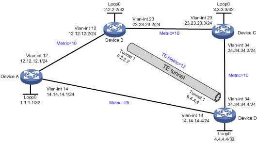
Analysis
· To make forwarding adjacency take effect, you must establish two MPLS TE tunnels in opposite directions between Device B and Device D, and enable forwarding adjacency on both devices.
· For the MPLS TE tunnel to use the path Device B—Device C—Device D, configure the path as the explicit path for the tunnel.
· For traffic from Device A to Device D to be forwarded through the MPLS TE tunnel, make sure the tunnel's metric is less than 15 (metric 25 minus 10). This example uses 12.
Procedures
1. Configure IP addresses for interfaces, configure basic OSPF, and set OSPF costs. (Details not shown.) For the configuration, see "Configuration files."
2. Enable MPLS TE on each node and interface that the MPLS TE tunnel traverses:
# On Device B, configure an LSR ID, and enable MPLS, MPLS TE, and RSVP-TE.
[DeviceB] mpls lsr-id 2.2.2.2
[DeviceB] mpls te
[DeviceB-te] quit
[DeviceB] rsvp
[DeviceB-rsvp] quit
[DeviceB] interface vlan-interface 23
[DeviceB-Vlan-interface23] mpls enable
[DeviceB-Vlan-interface23] mpls te enable
[DeviceB-Vlan-interface23] rsvp enable
[DeviceB-Vlan-interface23] quit
# On Device C, configure an LSR ID, and enable MPLS, MPLS TE, and RSVP-TE.
[DeviceC] mpls lsr-id 3.3.3.3
[DeviceC] mpls te
[DeviceC-te] quit
[DeviceC] rsvp
[DeviceC-rsvp] quit
[DeviceC] interface vlan-interface 23
[DeviceC-Vlan-interface23] mpls enable
[DeviceC-Vlan-interface23] mpls te enable
[DeviceC-Vlan-interface23] rsvp enable
[DeviceC-Vlan-interface23] ospf cost 10
[DeviceC-Vlan-interface23] quit
[DeviceC] interface vlan-interface 34
[DeviceC-Vlan-interface34] mpls enable
[DeviceC-Vlan-interface34] mpls te enable
[DeviceC-Vlan-interface34] rsvp enable
[DeviceC-Vlan-interface34] ospf cost 10
[DeviceC-Vlan-interface34] quit
# On Device D, configure an LSR ID, and enable MPLS, MPLS TE, and RSVP-TE.
[DeviceD] mpls lsr-id 4.4.4.4
[DeviceD] mpls te
[DeviceD-te] quit
[DeviceD] rsvp
[DeviceD-rsvp] quit
[DeviceD] interface vlan-interface 34
[DeviceD-Vlan-interface34] mpls enable
[DeviceD-Vlan-interface34] mpls te enable
[DeviceD-Vlan-interface34] rsvp enable
[DeviceD-Vlan-interface34] quit
3. Configure OSPF TE to advertise link TE attributes:
# On Device B, enable opaque LSA advertisement and reception, and enable MPLS TE for OSPF area 0. By default, opaque LSA advertisement and reception are enabled.
[DeviceB] ospf
[DeviceB-ospf-1] opaque-capability enable
[DeviceB-ospf-1] area 0
[DeviceB-ospf-1-area-0.0.0.0] mpls te enable
[DeviceB-ospf-1-area-0.0.0.0] quit
[DeviceB-ospf-1] quit
# On Device C, enable opaque LSA advertisement and reception, and enable MPLS TE for OSPF area 0. By default, opaque LSA advertisement and reception are enabled.
[DeviceC] ospf
[DeviceC-ospf-1] opaque-capability enable
[DeviceC-ospf-1] area 0
[DeviceC-ospf-1-area-0.0.0.0] mpls te enable
[DeviceC-ospf-1-area-0.0.0.0] quit
[DeviceC-ospf-1] quit
# On Device D, enable opaque LSA advertisement and reception, and enable MPLS TE for OSPF area 0. By default, opaque LSA advertisement and reception are enabled.
[DeviceD] ospf
[DeviceD-ospf-1] opaque-capability enable
[DeviceD-ospf-1] area 0
[DeviceD-ospf-1-area-0.0.0.0] mpls te enable
[DeviceD-ospf-1-area-0.0.0.0] quit
[DeviceD-ospf-1] quit
4. Configure MPLS TE tunnels:
# On Device B, configure MPLS TE tunnel interface Tunnel 1, and specify the tunnel destination address as the LSR ID of Device D.
[DeviceB] interface tunnel 1 mode mpls-te
[DeviceB-Tunnel1] ip address 9.2.2.2 255.255.255.0
[DeviceB-Tunnel1] destination 4.4.4.4
# Configure MPLS TE to use RSVP-TE to establish the tunnel.
[DeviceB-Tunnel1] mpls te signaling rsvp-te
[DeviceB-Tunnel1] quit
# Configure an explicit path named tun1.
[DeviceB] explicit-path tun1
[DeviceB-explicit-path-tun1] nexthop 23.23.23.3
[DeviceB-explicit-path-tun1] nexthop 34.34.34.4
[DeviceB-explicit-path-tun1]quit
# Specify the explicit path to be used as tun1.
[DeviceB] interface tunnel 1
[DeviceB–Tunnel1] mpls te path preference 1 explicit-path tun1
# Enable forwarding adjacency for the tunnel.
[DeviceA-Tunnel1] mpls te igp advertise
# Enable OSPF on tunnel interface Tunnel 1 and set the OSPF cost to 12 on the interface.
[DeviceA-Tunnel1] ospf 1 area 0
[DeviceA-Tunnel1] ospf cost 12
[DeviceA-Tunnel1] quit
# On Device D, configure MPLS TE tunnel interface Tunnel 1, and specify the tunnel destination address as the LSR ID of Device B.
[DeviceD] interface tunnel 1 mode mpls-te
[DeviceD-Tunnel1] ip address 9.4.4.4 255.255.255.0
[DeviceD-Tunnel1] destination 2.2.2.2
# Configure MPLS TE to use RSVP-TE to establish the tunnel.
[DeviceD-Tunnel1] mpls te signaling rsvp-te
[DeviceD-Tunnel1] quit
# Configure an explicit path named tun1.
[DeviceD] explicit-path tun1
[DeviceD-explicit-path-tun1] nexthop 34.34.34.3
[DeviceD-explicit-path-tun1] nexthop 23.23.23.2
[DeviceD-explicit-path-tun1]quit
# Specify the explicit path to be used as tun1.
[DeviceD] interface tunnel 1
[DeviceD–Tunnel1] mpls te path preference 1 explicit-path tun1
# Enable forwarding adjacency for the tunnel.
[DeviceD-Tunnel1] mpls te igp advertise
# Enable OSPF on tunnel interface Tunnel 1 and set the OSPF cost to 12 on the interface.
[DeviceD-Tunnel1] ospf 1 area 0
[DeviceD-Tunnel1] ospf cost 12
[DeviceD-Tunnel1] quit
Verifying the configuration
# Verify that the tunnel interfaces on Device B and Device D are up. This example uses Device B.
[DeviceB] display interface tunnel brief
Brief information on interfaces in route mode:
Link: ADM - administratively down; Stby - standby
Protocol: (s) - spoofing
Interface Link Protocol Primary IP Description
Tun1 UP UP 9.2.2.2 Tunnel1 Interface
# Display routing table information on Device A. The output shows that the next hop of the route to Device D is Device B, and the cost is 22. The MPLS TE tunnel has been used during IGP route calculation.
[Device A] display ip routing-table
Destinations : 24 Routes : 24
Destination/Mask Proto Pre Cost NextHop Interface
0.0.0.0/32 Direct 0 0 127.0.0.1 InLoop0
1.1.1.1/32 Direct 0 0 127.0.0.1 InLoop0
2.2.2.2/32 OSPF 10 10 12.12.12.2 Vlan12
3.3.3.3/32 OSPF 10 20 12.12.12.2 Vlan12
4.4.4.4/32 OSPF 10 22 12.12.12.2 Vlan12
9.2.2.0/24 OSPF 10 22 12.12.12.2 Vlan12
9.4.4.0/24 OSPF 10 34 12.12.12.2 Vlan12
12.12.12.0/24 Direct 0 0 12.12.12.1 Vlan12
12.12.12.0/32 Direct 0 0 12.12.12.1 Vlan12
12.12.12.1/32 Direct 0 0 127.0.0.1 InLoop0
12.12.12.255/32 Direct 0 0 12.12.12.1 Vlan12
14.14.14.0/24 Direct 0 0 14.14.14.1 Vlan14
14.14.14.0/32 Direct 0 0 14.14.14.1 Vlan14
14.14.14.1/32 Direct 0 0 127.0.0.1 InLoop0
14.14.14.255/32 Direct 0 0 14.14.14.1 Vlan14
23.23.23.0/24 OSPF 10 20 12.12.12.2 Vlan12
34.34.34.0/24 OSPF 10 30 12.12.12.2 Vlan12
127.0.0.0/8 Direct 0 0 127.0.0.1 InLoop0
127.0.0.0/32 Direct 0 0 127.0.0.1 InLoop0
127.0.0.1/32 Direct 0 0 127.0.0.1 InLoop0
127.255.255.255/32 Direct 0 0 127.0.0.1 InLoop0
224.0.0.0/4 Direct 0 0 0.0.0.0 NULL0
224.0.0.0/24 Direct 0 0 0.0.0.0 NULL0
255.255.255.255/32 Direct 0 0 127.0.0.1 InLoop0
Configuration files
· Device A:
#
ospf 1
area 0.0.0.0
network 1.1.1.1 0.0.0.0
network 12.12.12.0 0.0.0.255
network 14.14.14.0 0.0.0.255
#
vlan 12
#
vlan 14
#
interface LoopBack0
ip address 1.1.1.1 255.255.255.255
#
interface Vlan-interface12
ip address 12.12.12.1 255.255.255.0
ospf cost 10
#
interface Vlan-interface14
ip address 14.14.14.1 255.255.255.0
ospf cost 25
· Device B:
#
ospf 1
area 0.0.0.0
network 2.2.2.2 0.0.0.0
network 12.12.12.0 0.0.0.255
network 23.23.23.0 0.0.0.255
mpls te enable
#
mpls lsr-id 2.2.2.2
#
mpls te
#
explicit-path tun1
nexthop index 1 23.23.23.3 include strict
nexthop index 101 34.34.34.4 include strict
#
rsvp
#
vlan 12
#
vlan 23
#
interface LoopBack0
ip address 2.2.2.2 255.255.255.255
#
interface Vlan-interface12
ip address 12.12.12.2 255.255.255.0
ospf cost 10
#
interface Vlan-interface23
ip address 23.23.23.2 255.255.255.0
ospf cost 10
mpls enable
mpls te enable
rsvp enable
#
interface Tunnel1 mode mpls-te
ip address 9.2.2.2 255.255.255.0
ospf cost 12
ospf 1 area 0.0.0.0
mpls te path preference 1 explicit-path tun1
mpls te igp advertise
destination 4.4.4.4
#
· Device C:
#
ospf 1
area 0.0.0.0
network 3.3.3.3 0.0.0.0
network 23.23.23.0 0.0.0.255
network 34.34.34.0 0.0.0.255
mpls te enable
#
mpls lsr-id 3.3.3.3
#
mpls te
#
rsvp
#
vlan 23
#
vlan 34
#
interface LoopBack0
ip address 3.3.3.3 255.255.255.255
#
interface Vlan-interface23
ip address 23.23.23.3 255.255.255.0
ospf cost 10
mpls enable
mpls te enable
rsvp enable
#
interface Vlan-interface34
ip address 34.34.34.3 255.255.255.0
ospf cost 10
mpls enable
mpls te enable
rsvp enable
#
· Device D:
#
ospf 1
area 0.0.0.0
network 4.4.4.4 0.0.0.0
network 14.14.14.0 0.0.0.255
network 34.34.34.0 0.0.0.255
mpls te enable
#
mpls lsr-id 4.4.4.4
#
mpls te
#
explicit-path tun1
nexthop index 1 34.34.34.3 include strict
nexthop index 101 23.23.23.2 include strict
#
rsvp
#
vlan 14
#
vlan 34
#
interface LoopBack0
ip address 4.4.4.4 255.255.255.255
#
interface Vlan-interface14
ip address 14.14.14.4 255.255.255.0
ospf cost 25
#
interface Vlan-interface34
ip address 34.34.34.4 255.255.255.0
ospf cost 10
mpls enable
mpls te enable
rsvp enable
#
interface Tunnel1 mode mpls-te
ip address 9.4.4.4 255.255.255.0
ospf cost 12
ospf 1 area 0.0.0.0
mpls te path preference 1 explicit-path tun1
mpls te igp advertise
destination 2.2.2.2
#
Related documentation
· H3C S7500E-XS Switch Series MPLS Configuration Guide-R757X
· H3C S7500E-XS Switch Series MPLS Command Reference-R757X