- Table of Contents
-
- 07-MPLS Configuration Examples
- 01-H3C_HoVPN_Configuration_Examples
- 02-H3C_MCE_Configuration_Examples
- 03-H3C_MPLS_L2VPN_Configuration_Examples
- 04-H3C_MPLS_L3VPN_Configuration_Examples
- 05-H3C_MPLS_TE_Configuration_Examples
- 06-H3C_MPLS_TE_Forwarding_Adjacency_Configuration_Examples
- 07-H3C_Basic_MPLS_Configuration_Examples
- 08-H3C_VPLS_Configuration_Examples
- 09-H3C_GRE Tunnel Access to MPLS L3VPN Configuration Examples
- Related Documents
-
| Title | Size | Download |
|---|---|---|
| 01-H3C_HoVPN_Configuration_Examples | 142.10 KB |
H3C HoVPN Configuration Examples
Software version: Release 7577P04
Document version: 6W100-20190330
Copyright © 2019 New H3C Technologies Co., Ltd. All rights reserved.
No part of this manual may be reproduced or transmitted in any form or by any means without prior written consent of New H3C Technologies Co., Ltd.
Except for the trademarks of New H3C Technologies Co., Ltd., any trademarks that may be mentioned in this document are the property of their respective owners.
The information in this document is subject to change without notice.
Contents
Introduction
This document provides MPLS HoVPN configuration examples.
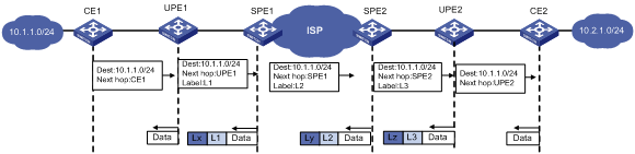
Hierarchy of VPN (HoVPN) divides PEs into underlayer PEs (UPEs) or user-end PEs, and superstratum PEs (SPEs) or service provider-end PEs. UPEs and SPEs form a hierarchical PE structure.
UPEs and SPEs together provide the functions of a conventional PE.
· UPE—Provides user access. It maintains the routes of directly connected VPN sites. It does not maintain the routes of the remote sites in the VPN, or it only maintains their summary routes. A UPE assigns inner labels to the routes of its directly connected sites, and advertises the labels along with VPN routes to the SPE through MP-BGP.
· SPE—Manages and advertises VPN routes. It maintains all the routes of the VPNs connected through UPEs, including the routes of both the local and remote sites. An SPE advertises routes along with labels to UPEs, including the default routes of VPN instances or summary routes and the routes permitted by the routing policy. By using routing policies, you can control which sites in a VPN can communicate with each other.
Figure 1 Routing process and label exchange for HoVPN
Prerequisites
This document is not restricted to specific software or hardware versions.
The configuration examples in this document were created and verified in a lab environment, and all the devices were started with the factory default configuration. When you are working on a live network, make sure you understand the potential impact of every command on your network.
This document assumes that you have basic knowledge of HoVPN.
Example: Configuring HoVPN
Network configuration
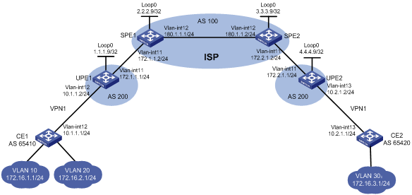
As shown in Figure 2, configure HoVPN and routing policies to allow communication between VLAN 10 and VLAN 30 and to disallow communication between VLAN 20 and VLAN 30.
Analysis
To ensure that VLAN 10 can communicate with VLAN 30 but VLAN 20 cannot, configure a routing policy on SPE 2 to advertise only the route of subnet 172.16.1.0/24 to UPE 2.
Restrictions and guidelines
When you configure HoVPN, follow these restrictions and guidelines:
· For an SPE to advertise routes to its connected UPE, perform the following configurations on the SPE:
? Configure a routing policy to specify the routes that can be advertised.
? Configure the BGP to advertise the routes permitted by the routing policy to the UPE.
· For an SPE and a UPE (EBGP peers) to advertise labels to each other, perform the following configurations:
? Enable BGP to exchange labeled routes with the peer.
? Configure a routing policy to specify the routes that can be advertised, and assign MPLS labels to the matching routes.
? Apply the routing policy to routes outgoing to the peer.
· Associating an interface with a VPN instance deletes the IP address of the interface. You must reconfigure the IP address of the interface after the association. To avoid configuring the interface's IP address twice, configure the association first.
Procedures
1. Enable MPLS and MPLS LDP on SPEs, and configure the IGP protocol (OSPF, in this example):
# On SPE 1, configure basic MPLS and MPLS LDP to establish LDP LSPs.
<SPE1> system-view
[SPE1] interface loopback 0
[SPE1-LoopBack0] ip address 2.2.2.9 32
[SPE1-LoopBack0] quit
[SPE1] mpls lsr-id 2.2.2.9
[SPE1] mpls ldp
[SPE1-ldp] quit
[SPE1] interface vlan-interface 11
[SPE1-Vlan-interface11] ip address 172.1.1.2 24
[SPE1-Vlan-interface11] mpls enable
[SPE1-Vlan-interface11] quit
[SPE1] interface vlan-interface 12
[SPE1-Vlan-interface12] ip address 180.1.1.1 24
[SPE1-Vlan-interface12] mpls enable
[SPE1-Vlan-interface12] mpls ldp enable
[SPE1-Vlan-interface12] quit
# On SPE 1, configure OSPF.
[SPE1] ospf
[SPE1-ospf-1] area 0
[SPE1-ospf-1-area-0.0.0.0] network 2.2.2.9 0.0.0.0
[SPE1-ospf-1-area-0.0.0.0] network 180.1.1.0 0.0.0.255
[SPE1-ospf-1-area-0.0.0.0] quit
[SPE1-ospf-1] quit
# On SPE 2, configure basic MPLS and MPLS LDP to establish LDP LSPs.
<SPE2> system-view
[SPE2] interface loopback 0
[SPE2-LoopBack0] ip address 3.3.3.9 32
[SPE2-LoopBack0] quit
[SPE2] mpls lsr-id 3.3.3.9
[SPE2] mpls ldp
[SPE2-ldp] quit
[SPE2] interface vlan-interface 12
[SPE2-Vlan-interface12] ip address 180.1.1.2 24
[SPE2-Vlan-interface12] mpls enable
[SPE2-Vlan-interface12] mpls ldp enable
[SPE2-Vlan-interface12] quit
[SPE2] interface vlan-interface 11
[SPE2-Vlan-interface11] ip address 172.2.1.2 24
[SPE2-Vlan-interface11] mpls enable
[SPE2-Vlan-interface11] quit
# On SPE 2, configure OSPF.
[SPE2] ospf
[SPE2-ospf-1] area 0
[SPE2-ospf-1-area-0.0.0.0] network 3.3.3.9 0.0.0.0
[SPE2-ospf-1-area-0.0.0.0] network 180.1.1.0 0.0.0.255
[SPE2-ospf-1-area-0.0.0.0] quit
[SPE2-ospf-1] quit
# Execute the display mpls ldp peer command to verify that an LDP session in Operational state has been established between the SPEs. (Details not shown.)
# Execute the display ospf peer command to verify that an OSPF neighbor relationship in FULL state has been established between the SPEs. (Details not shown.)
2. Establish an MP-IBGP peer relationship between SPE 1 and SPE 2 to exchange VPNv4 routes:
# On SPE 1, establish an MP-IBGP peer relationship with SPE 2.
[SPE1] bgp 100
[SPE1-bgp-default] peer 3.3.3.9 as-number 100
[SPE1-bgp-default] peer 3.3.3.9 connect-interface loopback 0
[SPE1-bgp-default] address-family vpnv4
[SPE1-bgp-default-vpnv4] peer 3.3.3.9 enable
[SPE1-bgp-default-vpnv4] quit
[SPE1-bgp-default] quit
# On SPE 2, establish an MP-IBGP peer relationship with SPE 1.
[SPE2] bgp 100
[SPE2-bgp-default] peer 2.2.2.9 as-number 100
[SPE2-bgp-default] peer 2.2.2.9 connect-interface loopback 0
[SPE2-bgp-default] address-family vpnv4
[SPE2-bgp-default-vpnv4] peer 2.2.2.9 enable
[SPE2-bgp-default-vpnv4] quit
[SPE2-bgp-default] quit
# Execute the display bgp peer vpnv4 command on the SPEs to verify that a BGP peer relationship in Established state has been established. (Details not shown.)
3. Configure basic MPLS on UPEs:
# Configure UPE 1.
<UPE1> system-view
[UPE1] interface loopback 0
[UPE1-LoopBack0] ip address 1.1.1.9 32
[UPE1-LoopBack0] quit
[UPE1] mpls lsr-id 1.1.1.9
[UPE1] interface vlan-interface 11
[UPE1-Vlan-interface11] ip address 172.1.1.1 24
[UPE1-Vlan-interface11] mpls enable
[UPE1-Vlan-interface11] quit
# Configure UPE 2.
<UPE2> system-view
[UPE2] interface loopback 0
[UPE2-Loopback0] ip address 4.4.4.9 32
[UPE2-Loopback0] quit
[UPE2] mpls lsr-id 4.4.4.9
[UPE2] interface vlan-interface 11
[UPE2-Vlan-interface11] ip address 172.2.1.1 24
[UPE2-Vlan-interface11] mpls enable
[UPE2-Vlan-interface11] quit
4. Establish EBGP peer relationships between SPEs and UPEs, and enable them to exchange labeled routes to establish BGP LSPs:
# Configure SPE 1.
[SPE1] bgp 100
[SPE1-bgp-default] peer 172.1.1.1 as-number 200
[SPE1-bgp-default] address-family ipv4
[SPE1-bgp-default-ipv4] peer 172.1.1.1 enable
[SPE1-bgp-default-ipv4] peer 172.1.1.1 label-route-capability
[SPE1-bgp-default-ipv4] peer 172.1.1.1 route-policy policy1 export
[SPE1-bgp-default-ipv4] network 2.2.2.9 255.255.255.255
[SPE1-bgp-default-ipv4] quit
[SPE1-bgp-default] quit
# On SPE 1, configure routing policy policy1 and set MPLS labels for routes.
[SPE1] route-policy policy1 permit node 0
[SPE1-route-policy-policy1-0] apply mpls-label
[SPE1-route-policy-policy1-0] quit
# Configure UPE 1.
[UPE1] bgp 200
[UPE1-bgp-default] peer 172.1.1.2 as-number 100
[UPE1-bgp-default] address-family ipv4
[UPE1-bgp-default-ipv4] peer 172.1.1.2 enable
[UPE1-bgp-default-ipv4] peer 172.1.1.2 label-route-capability
[UPE1-bgp-default-ipv4] peer 172.1.1.2 route-policy policy1 export
[UPE1-bgp-default-ipv4] network 1.1.1.9 255.255.255.255
[UPE1-bgp-default-ipv4] quit
[UPE1-bgp-default] quit
# On UPE 1, configure routing policy policy1 and set MPLS labels for routes.
[UPE1] route-policy policy1 permit node 0
[UPE1-route-policy-policy1-0] apply mpls-label
[UPE1-route-policy-policy1-0] quit
# Configure SPE 2.
[SPE2] bgp 100
[SPE2-bgp-default] peer 172.2.1.1 as-number 200
[SPE2-bgp-default] address-family ipv4
[SPE2-bgp-default-ipv4] peer 172.2.1.1 enable
[SPE2-bgp-default-ipv4] peer 172.2.1.1 label-route-capability
[SPE2-bgp-default-ipv4] peer 172.2.1.1 route-policy policy1 export
[SPE2-bgp-default-ipv4] network 3.3.3.9 255.255.255.255
[SPE2-bgp-default-ipv4] quit
[SPE2-bgp-default] quit
# On SPE 2, configure routing policy policy1 and set MPLS labels for routes.
[SPE2] route-policy policy1 permit node 0
[SPE2-route-policy-policy1-0] apply mpls-label
[SPE2-route-policy-policy1-0] quit
# Configure UPE 2.
[UPE2] bgp 200
[UPE2-bgp-default] peer 172.2.1.2 as-number 100
[UPE2-bgp-default] address-family ipv4
[UPE2-bgp-default-ipv4] peer 172.2.1.2 enable
[UPE2-bgp-default-ipv4] peer 172.2.1.2 label-route-capability
[UPE2-bgp-default-ipv4] peer 172.2.1.2 route-policy policy1 export
[UPE2-bgp-default-ipv4] network 4.4.4.9 255.255.255.255
[UPE2-bgp-default-ipv4] quit
[UPE2-bgp-default] quit
# On UPE 2, configure routing policy policy1 and set MPLS labels for routes.
[UPE2] route-policy policy1 permit node 0
[UPE2-route-policy-policy1-0] apply mpls-label
[UPE2-route-policy-policy1-0] quit
# Execute the display mpls lsp command on the SPEs and UPEs to verify that BGP LSPs have been established between each SPE and its connected UPE. (Details not shown.)
5. Establish MP-EBGP peer relationships between SPEs and UPEs, and configure HoVPN:
# On UPE 1, establish an MP-EBGP peer relationship with SPE 1.
[UPE1] bgp 200
[UPE1-bgp-default] peer 2.2.2.9 as-number 100
[UPE1-bgp-default] peer 2.2.2.9 connect-interface loopback 0
[UPE1-bgp-default] address-family vpnv4
[UPE1-bgp-default-vpnv4] peer 2.2.2.9 enable
# On UPE 1, allow the local AS number to appear in the AS_PATH attribute of the routes received.
[UPE1-bgp-default-vpnv4] peer 2.2.2.9 allow-as-loop
[UPE1-bgp-default-vpnv4] quit
# On SPE 1, configure VPN instance vpn1.
[SPE1] ip vpn-instance vpn1
[SPE1-vpn-instance-vpn1] route-distinguisher 100:1
[SPE1-vpn-instance-vpn1] vpn-target 100:1 both
[SPE1-vpn-instance-vpn1] quit
# On SPE 1, establish an MP-EBGP peer relationship with UPE 1, and specify UPE 1 as a UPE.
[SPE1] bgp 100
[SPE1-bgp-default] peer 1.1.1.9 as-number 200
[SPE1-bgp-default] peer 1.1.1.9 connect-interface loopback 0
[SPE1-bgp-default] address-family vpnv4
[SPE1-bgp-default-vpnv4] peer 1.1.1.9 enable
[SPE1-bgp-default-vpnv4] peer 1.1.1.9 upe
[SPE1-bgp-default-vpnv4] quit
# On SPE 1, create a BGP-VPN instance so the learned VPNv4 routes can be added into the BGP routing table of the VPN instance.
[SPE1-bgp-default] ip vpn-instance vpn1
[SPE1-bgp-default-vpn1] quit
[SPE1-bgp-default] quit
# On UPE 2, establish an MP-EBGP peer relationship with SPE 2.
[UPE2] bgp 200
[UPE2-bgp-default] peer 3.3.3.9 as-number 100
[UPE2-bgp-default] peer 3.3.3.9 connect-interface loopback 0
[UPE2-bgp-default] address-family vpnv4
[UPE2-bgp-default-vpnv4] peer 3.3.3.9 enable
# On UPE 2, allow the local AS number to appear in the AS_PATH attribute of the routes received.
[UPE2-bgp-default-vpnv4] peer 3.3.3.9 allow-as-loop
[UPE2-bgp-default-vpnv4] quit
# On SPE 2, configure VPN instance vpn1.
[SPE2] ip vpn-instance vpn1
[SPE2-vpn-instance-vpn1] route-distinguisher 100:1
[SPE2-vpn-instance-vpn1] vpn-target 100:1 both
[SPE2-vpn-instance-vpn1] quit
# On SPE 2, establish an MP-EBGP peer relationship with UPE 2, and specify UPE 2 as a UPE.
[SPE2] bgp 100
[SPE2-bgp-default] peer 4.4.4.9 as-number 200
[SPE2-bgp-default] peer 4.4.4.9 connect-interface loopback 0
[SPE2-bgp-default] address-family vpnv4
[SPE2-bgp-default-vpnv4] peer 4.4.4.9 enable
[SPE2-bgp-default-vpnv4] peer 4.4.4.9 upe
[SPE2-bgp-default-vpnv4] quit
# On SPE 2, create a BGP-VPN instance so the learned VPNv4 routes can be added into the BGP routing table of the VPN instance.
[SPE2-bgp-default] ip vpn-instance vpn1
[SPE2-bgp-default-vpn1] quit
[SPE2-bgp-default] quit
# Execute the display bgp peer vpnv4 command on the SPEs and UPEs to verify that a BGP peer relationship in Established state has been established between each SPE and its connected UPE. (Details not shown.)
6. Allow CE access to UPEs:
# On UPE 1, configure VPN instance vpn1 to allow CE 1 to access UPE 1.
[UPE1] ip vpn-instance vpn1
[UPE1-vpn-instance-vpn1] route-distinguisher 100:1
[UPE1-vpn-instance-vpn1] vpn-target 100:1 both
[UPE1-vpn-instance-vpn1] quit
[UPE1] interface vlan-interface 12
[UPE1-Vlan-interface12] ip binding vpn-instance vpn1
[UPE1-Vlan-interface12] ip address 10.1.1.2 24
[UPE1-Vlan-interface12] quit
# On UPE 1, establish an EBGP peer relationship with CE 1, and redistribute VPN routes into BGP.
[UPE1] bgp 200
[UPE1-bgp-default] ip vpn-instance vpn1
[UPE1-bgp-default-vpn1] peer 10.1.1.1 as-number 65410
[UPE1-bgp-default-vpn1] address-family ipv4 unicast
[UPE1-bgp-default-ipv4-vpn1] peer 10.1.1.1 enable
[UPE1-bgp-default-ipv4-vpn1] import-route direct
[UPE1-bgp-default-ipv4-vpn1] quit
[UPE1-bgp-default-vpn1] quit
# On CE 1, establish an EBGP peer relationship with UPE 1, and redistribute direct routes into BGP.
<CE1> system-view
[CE1] interface vlan-interface 12
[CE1-Vlan-interface12] ip address 10.1.1.1 255.255.255.0
[CE1-Vlan-interface12] quit
[CE1] bgp 65410
[CE1-bgp-default] peer 10.1.1.2 as-number 200
[CE1-bgp-default] address-family ipv4 unicast
[CE1-bgp-default-ipv4] peer 10.1.1.2 enable
[CE1-bgp-default-ipv4] import-route direct
[CE1-bgp-default-ipv4] quit
[CE1-bgp-default] quit
# On UPE 2, configure VPN instance vpn1 to allow CE 2 to access UPE 2.
[UPE2] ip vpn-instance vpn1
[UPE2-vpn-instance-vpn1] route-distinguisher 100:1
[UPE2-vpn-instance-vpn1] vpn-target 100:1 both
[UPE2-vpn-instance-vpn1] quit
[UPE2] interface vlan-interface 12
[UPE2-Vlan-interface12] ip binding vpn-instance vpn1
[UPE2-Vlan-interface12] ip address 10.2.1.2 24
[UPE2-Vlan-interface12] quit
# On UPE 2, establish an EBGP peer relationship with CE 2, and redistribute VPN routes into BGP.
[UPE2] bgp 200
[UPE2-bgp-default] ip vpn-instance vpn1
[UPE2-bgp-default-vpn1] peer 10.2.1.1 as-number 65420
[UPE2-bgp-default-vpn1] address-family ipv4 unicast
[UPE2-bgp-default-ipv4-vpn1] peer 10.2.1.1 enable
[UPE2-bgp-default-ipv4-vpn1] import-route direct
[UPE2-bgp-default-ipv4-vpn1] quit
[UPE2-bgp-default-vpn1] quit
# On CE 2, establish an EBGP peer relationship with UPE 2, and redistribute direct routes into BGP.
<CE2> system-view
[CE2] interface vlan-interface 12
[CE2-Vlan-interface12] ip address 10.2.1.1 255.255.255.0
[CE2-Vlan-interface12] quit
[CE2] bgp 65420
[CE2-bgp-default] peer 10.2.1.2 as-number 200
[CE2-bgp-default] address-family ipv4 unicast
[CE2-bgp-default-ipv4] peer 10.2.1.2 enable
[CE2-bgp-default-ipv4] import-route direct
[CE2-bgp-default-ipv4] quit
[CE2-bgp-default] quit
# Execute the display bgp peer ipv4 command on the UPEs and CEs to verify that a BGP peer relationship in Established state has been established between each UPE and its connected CE. (Details not shown.)
7. Configure routing policies on SPEs to filter VPN routes to be advertised:
# On SPE 1, advertise the routes permitted by routing policy policy2 (the routes of CE 2) to UPE 1.
[SPE1] ip prefix-list list1 index 10 permit 172.16.3.0 24
[SPE1] route-policy policy2 permit node 0
[SPE1-route-policy-policy2-0] if-match ip address prefix-list list1
[SPE1-route-policy-policy2-0] quit
[SPE1] bgp 100
[SPE1-bgp-default] address-family vpnv4
[SPE1-bgp-default-vpnv4] peer 1.1.1.9 upe route-policy policy2 export
# On SPE 2, advertise the routes permitted by routing policy policy2 (the routes of subnet 172.16.1.0 connected to CE 1) to UPE 2.
[SPE2] ip prefix-list list1 index 10 permit 172.16.1.0 24
[SPE2] route-policy policy2 permit node 0
[SPE2-route-policy-policy2-0] if-match ip address prefix-list list1
[SPE2-route-policy-policy2-0] quit
[SPE2] bgp 100
[SPE2-bgp-default] address-family vpnv4
[SPE2-bgp-default-vpnv4] peer 4.4.4.9 upe route-policy policy2 export
Verifying the configuration
# Verify that CE 1 has learned the route to subnet 172.16.3.0/24 of CE 2.
[CE1]display ip routing-table
Destinations : 25 Routes : 25
Destination/Mask Proto Pre Cost NextHop Interface
172.16.1.0/24 Direct 0 0 172.16.1.1 VLAN10
172.16.1.0/32 Direct 0 0 172.16.1.1 VLAN10
172.16.1.1/32 Direct 0 0 127.0.0.1 InLoop0
172.16.1.255/32 Direct 0 0 172.16.1.1 VLAN10
172.16.2.0/24 Direct 0 0 172.16.2.1 VLAN20
172.16.2.0/32 Direct 0 0 172.16.2.1 VLAN20
172.16.2.1/32 Direct 0 0 127.0.0.1 InLoop0
172.16.2.255/32 Direct 0 0 172.16.2.1 VLAN20
172.16.3.0/24 BGP 255 0 10.1.1.2 VLAN12
# Verify that CE 2 has learned the route to subnet 172.16.1.0/24 of CE 1, but it has not learned the route to 172.16.2.0/24 of CE 1.
[CE2] display ip routing-table
Destinations : 21 Routes : 21
Destination/Mask Proto Pre Cost NextHop Interface
172.16.1.0/24 BGP 255 0 10.2.1.2 VLAN13
172.16.3.0/24 Direct 0 0 172.16.3.1 VLAN30
172.16.3.0/32 Direct 0 0 172.16.3.1 VLAN30
172.16.3.1/32 Direct 0 0 127.0.0.1 InLoop0
172.16.3.255/32 Direct 0 0 172.16.3.1 VLAN30
# Verify that VLAN 10 and VLAN 30 can ping each other, and VLAN 20 and VLAN 30 cannot ping each other. (Details not shown.)
Configuration files
· CE 1:
#
vlan 10
#
vlan 12
#
vlan 20
#
interface Vlan-interface10
ip address 172.16.1.1 255.255.255.0
#
interface Vlan-interface12
ip address 10.1.1.1 255.255.255.0
#
interface Vlan-interface20
ip address 172.16.2.1 255.255.255.0
#
interface Ten-GigabitEthernet1/1/1
port link-mode bridge
port access vlan 10
#
interface Ten-GigabitEthernet1/1/2
port link-mode bridge
port access vlan 20
#
interface Ten-GigabitEthernet1/1/3
port link-mode bridge
port access vlan 12
#
bgp 65410
peer 10.1.1.2 as-number 200
#
address-family ipv4 unicast
import-route direct
peer 10.1.1.2 enable
#
· CE 2:
#
vlan 13
#
vlan 30
#
interface Vlan-interface13
ip address 10.2.1.1 255.255.255.0
#
interface Vlan-interface30
ip address 172.16.3.1 255.255.255.0
#
interface Ten-GigabitEthernet1/1/1
port link-mode bridge
port access vlan 30
#
interface Ten-GigabitEthernet1/1/2
port link-mode bridge
port access vlan 13
#
bgp 65420
peer 10.2.1.2 as-number 200
#
address-family ipv4 unicast
import-route direct
peer 10.2.1.2 enable
#
· UPE 1:
#
ip vpn-instance vpn1
route-distinguisher 100:1
vpn-target 100:1 import-extcommunity
vpn-target 100:1 export-extcommunity
#
mpls lsr-id 1.1.1.9
#
vlan 11 to 12
#
interface LoopBack0
ip address 1.1.1.9 255.255.255.255
#
interface Vlan-interface11
ip address 172.1.1.1 255.255.255.0
mpls enable
#
interface Vlan-interface12
ip binding vpn-instance vpn1
ip address 10.1.1.2 255.255.255.0
#
interface Ten-GigabitEthernet1/1/1
port link-mode bridge
port access vlan 11
#
interface Ten-GigabitEthernet1/1/2
port link-mode bridge
port access vlan 12
#
bgp 200
peer 2.2.2.9 as-number 100
peer 2.2.2.9 connect-interface LoopBack0
peer 172.1.1.2 as-number 100
#
address-family ipv4 unicast
import-route direct
network 1.1.1.9 255.255.255.255
network 172.1.1.0 255.255.255.0
peer 172.1.1.2 enable
peer 172.1.1.2 route-policy hope export
peer 172.1.1.2 label-route-capability
#
address-family vpnv4
peer 2.2.2.9 enable
peer 2.2.2.9 allow-as-loop 1
#
ip vpn-instance vpn1
peer 10.1.1.1 as-number 65410
#
address-family ipv4 unicast
import-route direct
peer 10.1.1.1 enable
#
route-policy hope permit node 0
apply mpls-label
#
· SPE 1:
#
ip vpn-instance vpn1
route-distinguisher 100:1
vpn-target 100:1 import-extcommunity
vpn-target 100:1 export-extcommunity
#
ospf 1
area 0.0.0.0
network 2.2.2.9 0.0.0.0
network 180.1.1.0 0.0.0.255
#
mpls lsr-id 2.2.2.9
#
vlan 11 to 12
#
mpls ldp
#
interface LoopBack0
ip address 2.2.2.9 255.255.255.255
#
interface Vlan-interface11
ip address 172.1.1.2 255.255.255.0
mpls enable
#
interface Vlan-interface12
ip address 180.1.1.1 255.255.255.0
mpls enable
mpls ldp enable
#
interface Ten-GigabitEthernet1/1/1
port link-mode bridge
port access vlan 11
#
interface Ten-GigabitEthernet1/1/2
port link-mode bridge
port access vlan 12
#
bgp 100
peer 1.1.1.9 as-number 200
peer 1.1.1.9 connect-interface LoopBack0
peer 3.3.3.9 as-number 100
peer 3.3.3.9 connect-interface LoopBack0
peer 172.1.1.1 as-number 200
#
address-family ipv4 unicast
network 2.2.2.9 255.255.255.255
peer 172.1.1.1 enable
peer 172.1.1.1 route-policy policy1 export
peer 172.1.1.1 label-route-capability
#
address-family vpnv4
peer 1.1.1.9 enable
peer 1.1.1.9 upe
peer 1.1.1.9 upe route-policy policy2 export
peer 3.3.3.9 enable
#
ip vpn-instance vpn1
#
route-policy policy1 permit node 0
apply mpls-label
#
route-policy policy2 permit node 0
if-match ip address prefix-list list1
#
ip prefix-list list1 index 10 permit 172.16.3.0 24
· UPE 2:
#
ip vpn-instance vpn1
route-distinguisher 100:1
vpn-target 100:1 import-extcommunity
vpn-target 100:1 export-extcommunity
#
mpls lsr-id 4.4.4.9
#
vlan 11
#
vlan 13
#
interface LoopBack0
ip address 4.4.4.9 255.255.255.255
#
interface Vlan-interface11
ip address 172.2.1.1 255.255.255.0
mpls enable
#
interface Vlan-interface13
ip binding vpn-instance vpn1
ip address 10.2.1.2 255.255.255.0
#
interface Ten-GigabitEthernet1/1/1
port link-mode bridge
port access vlan 11
#
interface Ten-GigabitEthernet1/1/2
port link-mode bridge
port access vlan 13
#
bgp 200
peer 3.3.3.9 as-number 100
peer 3.3.3.9 connect-interface LoopBack0
peer 172.2.1.2 as-number 100
#
address-family ipv4 unicast
network 4.4.4.9 255.255.255.255
peer 172.2.1.2 enable
peer 172.2.1.2 route-policy hope export
peer 172.2.1.2 label-route-capability
#
address-family vpnv4
peer 3.3.3.9 enable
peer 3.3.3.9 allow-as-loop 1
#
ip vpn-instance vpn1
peer 10.2.1.1 as-number 65420
#
address-family ipv4 unicast
import-route direct
peer 10.2.1.1 enable
#
route-policy hope permit node 0
apply mpls-label
· SPE 2:
#
ip vpn-instance vpn1
route-distinguisher 100:1
vpn-target 100:1 import-extcommunity
vpn-target 100:1 export-extcommunity
#
ospf 1
area 0.0.0.0
network 3.3.3.9 0.0.0.0
network 180.1.1.0 0.0.0.255
#
mpls lsr-id 3.3.3.9
#
vlan 11 to 12
#
mpls ldp
#
interface LoopBack0
ip address 3.3.3.9 255.255.255.255
#
interface Vlan-interface11
ip address 172.2.1.2 255.255.255.0
mpls enable
#
interface Vlan-interface12
ip address 180.1.1.2 255.255.255.0
mpls enable
mpls ldp enable
#
interface Ten-GigabitEthernet1/1/1
port link-mode bridge
port access vlan 11
#
interface Ten-GigabitEthernet1/1/2
port link-mode bridge
port access vlan 12
#
bgp 100
router-id 3.3.3.9
peer 2.2.2.9 as-number 100
peer 2.2.2.9 connect-interface LoopBack0
peer 4.4.4.9 as-number 200
peer 4.4.4.9 connect-interface LoopBack0
peer 172.2.1.1 as-number 200
#
address-family ipv4 unicast
network 3.3.3.9 255.255.255.255
peer 172.2.1.1 enable
peer 172.2.1.1 route-policy policy1 export
peer 172.2.1.1 label-route-capability
#
address-family vpnv4
peer 2.2.2.9 enable
peer 4.4.4.9 enable
peer 4.4.4.9 upe
peer 4.4.4.9 upe route-policy policy2 export
#
ip vpn-instance vpn1
#
route-policy policy1 permit node 0
apply mpls-label
#
route-policy policy2 permit node 0
if-match ip address prefix-list list1
#
ip prefix-list list1 index 10 permit 172.16.1.0 24
Related documentation
· H3C S7500E-XS Switch Series MPLS Command Reference-R757X
· H3C S7500E-XS Switch Series MPLS Configuration Guide-R757X