- Table of Contents
-
- 02-WLAN Configuration Guide
- 00-Preface
- 01-WLAN Interface Configuration
- 02-WLAN Access Configuration
- 03-WLAN Security Configuration
- 04-IACTP Tunnel and WLAN Roaming Configuration
- 05-WLAN RRM Configuration
- 06-WLAN IDS Configuration
- 07-WLAN QoS Configuration
- 08-WLAN Mesh Link Configuration
- 09-Advanced WLAN Configuration
- 10-WLAN High Availability Configuration
- 11-WLAN IPS Configuration
- 12-WLAN Optimization Configuration
- Related Documents
-
| Title | Size | Download |
|---|---|---|
| 10-WLAN High Availability Configuration | 262.42 KB |
Displaying AC backup connection status
AC backup configuration example
Configuring client information backup
Configuring client information backup
Displaying and maintaining client information backup
Client information backup configuration example
Uplink detection configuration example
Configuring AC backup
Overview
AC backup enables each AP to establish tunnels with a primary AC and a backup AC. The two ACs must have the same configuration for each AP. The primary AC provides services to all APs. If the primary AC fails, the backup AC becomes the new primary AC to provide services. The two ACs use a heartbeat mechanism to make sure the failure of the primary AC is quickly detected by the backup AC.
Primary AC recovery
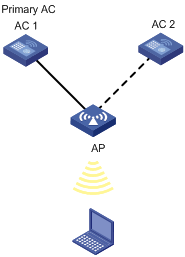
As shown in Figure 1, AC 1 is the primary AC, and AC 2 is the backup AC. Configure connection priority of 7 on AC 1. If AC 1 goes down, the AP connects to AC 2. AC 2 is the primary AC before the connection between AC 1 and the AP recovers. When AC 1 recovers, the primary AC recovery feature enables AC 1 to immediately become the primary AC.
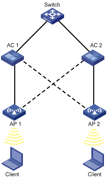
Active/active mode
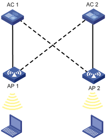
In active/active mode, both ACs are active. Each AC acts as the primary AC for some APs and acts as the backup AC for some other APs. In Figure 2, AC 1 acts as the primary AC for AP 1 and backup AC for AP 2. AC 2 acts as the primary AC for AP 2 and backup AC for AP 1.
AC backup
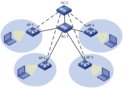
As shown in Figure 3, AC 1 is the primary AC that provides services to AP 1, AP 2, AP 3, and AP 4 through primary tunnels. AC 2 is the backup AC that connects to APs through backup tunnels. When AC 1 fails, AC 2 can quickly detect the failure, and become the primary AC to provide services to APs. All APs change backup tunnels to AC 2 to primary tunnels. When AC 1 recovers, it still acts as the backup AC.
Configuring AC backup
Follow these guidelines when you configure AC backup:
· To modify the wireless configurations of an AP, modify the configurations on the backup AC first to make sure the AP information can be backed up properly.
· The two ACs must have the same AP configuration. Otherwise, after a primary/backup switchover, the AP might fail to work.
· For the EWPX2WCMD0, LSRM1WCM3A1, and LSQM1WCMD0 cards, make sure the Ten-GigabitEthernet 1/0/1 interface is up and configure the interface to permit the VLAN specified by the hot-backup vlan vlan-id command.
· For the WX5004, WX5002V2, WX3510E, and WX3540E, configure a heartbeat interval greater than 1.2 seconds.
· For the EWPX1WCMD0, LSQM1WCMD0, LSRM1WCM3A1, and LSUM3WCMD0, if the heartbeat interval is smaller than 1000 ms and the two Ten-GigabitEthernet interfaces are aggregate interfaces, do not shutdown any of the two interfaces.
· For the EWPXM1WCME0 and LSUM1WCME0, if the heartbeat interval is smaller than 1000 ms and the four Ten-GigabitEthernet interfaces are aggregate interfaces, do not shutdown any one of the four interfaces.
To configure AC backup:
|
Step |
Command |
Remarks |
|
1. Enter system view. |
system-view |
N/A |
|
2. Specify an IPv4/IPv6 backup AC. |
wlan backup-ac { ip ipv4-address | ipv6 ipv6-address } |
Optional. By default, no backup AC is specified. The backup AC configured in AP template view takes precedence over that configured in system view. |
|
3. Specify a priority for the probe response packets sent by the AC to the AP. |
wlan controller priority priority |
The priority value must be in the range of 1 to 16. By default, the priority for the probe response packets is 7. |
|
4. Enter AP template view. |
wlan ap ap-name [ model model-name [ id ap-id ] ] |
Specify the model name only when you create an AP template. |
|
5. Specify an IPv4/IPv6 backup AC. |
backup-ac { ip ipv4-address | ipv6 ipv6-address } |
Optional. By default, no IPv4/IPv6 backup AC is configured and the global backup AC is used by the AP. |
|
6. Specify the AC connection priority for the AP. |
priority level priority |
Optional. By default, the AP connection priority is 4. An AC connection priority of 7 enables the AC to become the primary AC. When the primary AC fails and then recovers, it re-establishes connections with APs and become the primary AC. |
|
7. Return to system view. |
quit |
N/A |
|
8. Enable AC hot backup. |
hot-backup enable [ domain domain-id ] * |
Optional. By default, AC hot backup is disabled. Support for this feature depends on your device model. For more information, see About the H3C Access Controllers Configuration Guides. |
|
9. Specify the VLAN ID for the ports transmitting data between ACs. |
hot-backup vlan vlan-id |
Optional. By default, the VLAN ID is 1. Support for this feature depends on your device model. For more information, see About the H3C Access Controllers Configuration Guides. |
|
10. Specify the heartbeat interval between ACs. |
hot-backup hellointerval hellointerval |
Optional. By default, the heartbeat interval is 2000 milliseconds. |
|
11. Specify the delay for an AP to switch from a backup AC to a primary AC. |
wlan backup-ac switch-delay time |
By default, the delay for an AP to switch from a backup AC to a primary AC is 5 seconds. |
Displaying AC backup connection status
|
Task |
Command |
Remarks |
|
Display AC backup connection status on the primary AC. |
display hot-backup state [ | { begin | exclude | include } regular-expression ] |
Available in any view. |
AC backup configuration example
Network requirements
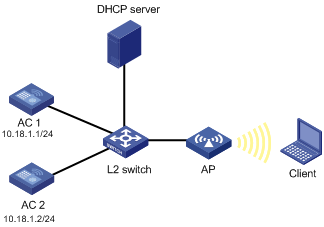
As shown in Figure 4, AC 1, AC 2, and the AP are in the same network. The AP gets its IP address from the DHCP server. AC 1 is the primary AC and AC 2 is the backup AC. When AC 1 fails, AC 2 can quickly detect the failure, and it becomes the primary AC to provide services to the AP.
Configuration procedure
1. Configure AC 1:
# Create a WLAN ESS interface.
<AC1> system-view
[AC1] interface WLAN-ESS 1
[AC1-WLAN-ESS1] quit
# Create a clear-type WLAN service template, configure the SSID of the service template as service, and bind interface WLAN-ESS 1 to this service template.
[AC1] wlan service-template 1 clear
[AC1-wlan-st-1] ssid service
[AC1-wlan-st-1] bind WLAN-ESS 1
[AC1-wlan-st-1] authentication-method open-system
[AC1-wlan-st-1] service-template enable
[AC1-wlan-st-1] quit
# Specify the backup AC address.
[AC1] wlan backup-ac ip 10.18.1.2
# Configure the AP on AC 1.
[AC1] wlan ap ap1 model wa3628i-AGN
[AC1-wlan-ap-ap1] serial-id 210235A29G007C000020
[AC1-wlan-ap-ap1] priority level 7
[AC1-wlan-ap-ap1] radio 1 type dot11an
[AC1-wlan-ap-ap1-radio-1] service-template 1
[AC1-wlan-ap-ap1-radio-1] radio enable
2. Configure AC 2:
# Create a WLAN ESS interface.
<AC2> system-view
[AC2] interface wlan-ess 1
[AC2-WLAN-ESS1] quit
# Create a clear-type WLAN service template, configure the SSID on AC 2 as service because the primary and backup ACs must have the same SSID, and bind interface WLAN-ESS 1 to this service template.
[AC2] wlan service-template 1 clear
[AC2-wlan-st-1] ssid service
[AC2-wlan-st-1] bind WLAN-ESS 1
[AC2-wlan-st-1] authentication-method open-system
[AC2-wlan-st-1] service-template enable
[AC2-wlan-st-1] quit
# Specify the backup AC address.
[AC2] wlan backup-ac ip 10.18.1.1
# Configure the AP on AC 2.
[AC2] wlan ap ap1 model WA3628i-AGN
[AC2-wlan-ap-ap1] serial-id 210235A29G007C000020
[AC2-wlan-ap-ap1] radio 1 type dot11an
[AC2-wlan-ap-ap1-radio-1] service-template 1
[AC2-wlan-ap-ap1-radio-1] radio enable
3. Verify the configuration:
When AC 1 fails, AC 2 immediately becomes the primary AC. You can use the display wlan ap command on the AC to view AP state.
Configuring client information backup
|
|
IMPORTANT: Support for this feature depends on the device model. For more information, see About the H3C Access Controllers Configuration Guides. |
In a network environment shown in Figure 5, to prevent clients from going offline because of unexpected primary/backup AC switchover, the ACs must support client information backup. This feature enables the primary AC to send client information in real time to the backup AC through an IACTP tunnel, ensuring consistency of client information on the two ACs. When a switchover occurs, the backup AC immediately takes over services for online clients to ensure service continuity.
This feature supports backing up information for clients that use 802.1X authentication and clients that use clear-type wireless services. For more information about 802.1X, see Security Configuration Guide. For more information about stateful failover, see High Availability Configuration Guide.
As shown in Figure 5, AC 1 and AC 2 back up each other. AC 1 is the primary AC of AP 1, AC 2 is the primary AC of AP 2, and the two ACs are in the same mobility group. When clients go online and offline or roaming between the ACs, the two ACs synchronize client information in real time to ensure consistent client information.
If an anomaly occurs, for example, AC 1 fails, the tunnel between AC 1 and AP 1 is terminated, or AC 2 detects that the tunnel to AC 1 is terminated, AC 2 becomes the primary AC of AP 1. During the switchover, clients associated with AP 1 are not logged off. When the anomaly is removed, AC 2 sends all client information to AC 1 to ensure consistent client information.
To check consistency of client information, use the following ways:
· Execute the display wlan client verbose command on both the primary and backup ACs. In the command output, if the client information, except the state (Running for the primary AC and Running(Backup) for the backup AC), is consistent on the two ACs, the basic client information has been synchronized.
· Execute the display wlan client roam-track mac-address command on both the primary and backup ACs to view roam-track information of the clients. If the information on the two ACs is consistent, the client roaming information has been synchronized.
Configuring client information backup
|
|
CAUTION: · The two ACs must communicate at Layer 2. · The two ACs must have the same AP configuration view settings for an AP. Otherwise, after a primary/backup switchover, the AP might fail to work. · If a primary/backup AC switchover occurs during the client information backup process, clients will be logged out and associated with the AC again because the backup AC does not have complete online client information. |
Before performing this task, complete the following tasks:
· Make sure the primary AC and the backup AC are in the same Layer 2 network.
· Configure a mobility group and configure AC backup on the two ACs.
For more information about mobility group configuration, see "Configuring IACTP tunnel and WLAN roaming." For more information about AC backup configuration, see "Configuring AC backup."
To configure client information backup:
|
Step |
Command |
Remarks |
|
1. Enter system view. |
system-view |
N/A |
|
2. Enable client information backup. |
wlan backup-client enable |
By default, client information backup is disabled. The stateful failover function takes effect only when client information backup is enabled on both the primary AC and backup AC. |
Displaying and maintaining client information backup
|
Task |
Command |
Remarks |
|
Display detailed client information. |
display wlan client [ ap ap-name [ radio radio-number ] | mac-address mac-address | service-template service-template-number ] [ verbose ] [ | { begin | exclude | include } regular-expression ] |
Available in any view. |
|
Display client roaming tracking information. |
display wlan client roam-track mac-address mac-address [ | { begin | exclude | include } regular-expression ] |
Available in any view. |
Client information backup configuration example
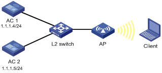
Network requirements
As shown in Figure 6, AC 1 and AC 2 support stateful failover. AC 1 is the primary AC. Enable client information backup on the two ACs so the clients can communicate during a primary/backup switchover.
Configuration procedure
1. Configure AC 1:
# Specify the backup AC.
<AC> system-view
[AC] wlan backup-ac ip 1.1.1.5
# Create WLAN interface WLAN-ESS 1.
[AC] interface wlan-ess 1
[AC-WLAN-ESS1] quit
# Create a clear-type service template, configure the SSID as abc, and bind WLAN-ESS 1 to the service template.
[AC] wlan service-template 1 clear
[AC-wlan-st-1] ssid abc
[AC-wlan-st-1] bind wlan-ess 1
[AC-wlan-st-1] authentication-method open-system
[AC-wlan-st-1] service-template enable
# Configure the AP.
[AC] wlan ap ap1 model wa3628i-AGN
[AC-wlan-ap-ap1] serial-id 210235A29G007C000020
[AC-wlan-ap-ap1] priority level 7
[AC-wlan-ap-ap1] radio 1 type dot11an
[AC-wlan-ap-ap1-radio-1] service-template 1
[AC-wlan-ap-ap1-radio-1] radio enable
[AC-wlan-ap-ap1-radio-1] quit
[AC-wlan-ap-ap1] quit
# Configure a mobility group, specify the IACTP tunnel source IP address as 1.1.1.4, and specify the tunnel destination address as 1.1.1.5.
[AC] wlan mobility-group roam
[AC-wlan-mg-roam] source ip 1.1.1.5
[AC-wlan-mg-roam] member ip 1.1.1.4
# Enable the mobility group.
[AC-wlan-mg-roam] mobility-group enable
# Enable client information backup.
[AC] wlan backup-client enable
2. Configure AC 2:
# Specify the backup AC.
<AC> system-view
[AC] wlan backup-ac ip 1.1.1.4
# Create WLAN interface WLAN-ESS 1.
[AC] interface wlan-ess 1
[AC-WLAN-ESS1] quit
# Create a clear-type service template, configure the SSID as abc, and bind WLAN-ESS 1 to the service template.
[AC] wlan service-template 1 clear
[AC-wlan-st-1] ssid abc
[AC-wlan-st-1] bind wlan-ess 1
[AC-wlan-st-1] authentication-method open-system
[AC-wlan-st-1] service-template enable
# Configure the AP.
[AC] wlan ap ap1 model wa3628i-AGN
[AC-wlan-ap-ap1] serial-id 210235A29G007C000020
[AC-wlan-ap-ap1] radio 1 type dot11an
[AC-wlan-ap-ap1-radio-1] service-template 1
[AC-wlan-ap-ap1-radio-1] radio enable
[AC-wlan-ap-ap1-radio-1] quit
[AC-wlan-ap-ap1] quit
# Configure a mobility group, specify the IACTP tunnel source IP address as 1.1.1.5, and specify the tunnel destination address as 1.1.1.4.
[AC] wlan mobility-group roam
[AC-wlan-mg-roam] source ip 1.1.1.5
[AC-wlan-mg-roam] member ip 1.1.1.4
# Enable the mobility group.
[AC-wlan-mg-roam] mobility-group enable
# Enable client information backup.
[AC] wlan backup-client enable
3. Verify the configuration:
¡ After the clients get online, you can execute the display wlan client verbose command on AC 1 to view detailed information about the clients and on AC 2 to verify that the client information has been synchronized between AC 1 and AC 2.
¡ Execute the display wlan client roam-track command on both ACs to view roam-track information of the clients. If the information on the two ACs is consistent, the client roaming information has been synchronized.
¡ When AC 1 fails, AC 2 becomes the primary AC. During the switchover, the clients are not logged out and can access the network through AC 2.
Configuring uplink detection
Configuring uplink detection
As shown in Figure 7, when the uplink of the AC fails, the uplink detection function can detect the failure and disable the radio on the AP. If the uplink recovers, the AC enables the radio on the AP. To achieve this, you need to configure collaboration between NQA, track, and uplink detection:
· When the track entry is in Positive state, the AC enables the radio of the AP. Wireless clients can associate with the AP.
· When the track entry is in Negative state, the AC disables the radio of the AP. Wireless clients cannot associate with the AP.
· When the track entry is in Invalid state, the AC does not change the radio state of the AP.
For more information about the track module, see High Availability Configuration Guide. For more information about NQA, see Network Management and Monitoring Configuration Guide.

To configure uplink detection:
|
Step |
Command |
Remarks |
|
1. Enter system view. |
system-view |
N/A |
|
2. Specify a track entry to detect if the uplink is reachable. |
wlan uplink track track-entry-number |
Optional. By default, no track entry is specified. |
|
|
NOTE: When the uplink of the AC fails, if a radio has mesh configured, the AC does not disable the radio even if you disable the mesh service before the next uplink down event. However, the next uplink down event can disable the radio. |
Uplink detection configuration example
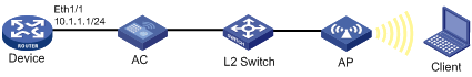
Network requirements
As shown in Figure 8, when the uplink of the AC fails, clients cannot access external networks if they are associated with the AP that is connected to the AC. Enable the uplink detection function so that when the uplink of the AC fails, clients are disabled from associating with the AP that is connected to the AC.
Configuration procedure
# Create an NQA test group with test type ICMP echo, and configure related test parameters.
<AC> system-view
[AC] nqa entry admin test
[AC-nqa-admin-test] type icmp-echo
[AC-nqa-admin-test-icmp-echo] destination ip 10.1.1.1
# Configure optional parameter frequency.
[AC-nqa-admin-test-icmp-echo] frequency 1000
# Configure reaction entry 1, specifying that five consecutive probe failures trigger the collaboration between the reaction entry and NQA.
[AC-nqa-admin-test-icmp-echo] reaction 1 checked-element probe-fail threshold-type consecutive 5 action-type trigger-only
[AC-nqa-admin-test-icmp-echo] quit
# Start the ICMP echo test.
[AC] nqa schedule admin test start-time now lifetime forever
# Configure track entry 1, and associate it with reaction entry 1 of the NQA test group (with the administrator admin, and the operation tag test).
[AC] track 1 nqa entry admin test reaction 1
# Specify track entry 1 for uplink detection.
[AC] wlan uplink track 1