- Table of Contents
-
- 02-WLAN Configuration Guide
- 00-Preface
- 01-WLAN Interface Configuration
- 02-WLAN Access Configuration
- 03-WLAN Security Configuration
- 04-IACTP Tunnel and WLAN Roaming Configuration
- 05-WLAN RRM Configuration
- 06-WLAN IDS Configuration
- 07-WLAN QoS Configuration
- 08-WLAN Mesh Link Configuration
- 09-Advanced WLAN Configuration
- 10-WLAN High Availability Configuration
- 11-WLAN IPS Configuration
- 12-WLAN Optimization Configuration
- Related Documents
-
| Title | Size | Download |
|---|---|---|
| 02-WLAN Access Configuration | 754.33 KB |
WLAN access configuration task list
Setting the maximum number of concurrent join requests that an AC can process
Setting a country/region code·
Configuring auto-AP authentication
Enabling unauthenticated auto APs to pass authentication and provide WLAN services
Converting auto APs to configured APs
Specifying a backup VLAN interface for AC association
Configuring parameters for an AP
Enabling AC-AP tunnel encryption with IPsec
Setting the echo interval for an AP
Specifying a configuration file for an AP
Configuring AP traffic protection
Enabling the AC to accept APs with a different software version
Configuring a WLAN service template
Creating a service template and setting an SSID
Configuring the country code to be carried in beacon frames
Enabling an authentication method
Binding a WLAN-ESS interface to the service template
Enabling centralized forwarding for client DHCP packets
Configuring client authentication
Setting the maximum number of associated clients
Configuring beacon measurement
Configuring the client cache aging time
Configuring basic radio parameters
Enabling automatic creation of radio policies by the SNMP set operation
Mapping a service template to the radio
Configuring IP address match criteria for an AP group
Setting the statistics report interval
Setting the memory utilization threshold for an AP
Restoring the factory default settings of APs
Enabling automatic heating for an outdoor AP
Enabling SNMP traps for the WLAN module·
Configuring client IP address monitoring
Configuring management packet statistics collection
Displaying and maintaining WLAN access
Configuring WLAN access control
Configuring AP-based access control
Configuring SSID-based access control
WLAN access configuration examples
WLAN access configuration example
Configuring the same SSID to provide different access modes
Auto-AP authentication configuration example
Configuration example for AC-AP tunnel encryption with IPsec
Policy-based forwarding configuration example
802.11ac configuration example
Backup client authentication configuration example
Local client authentication configuration example
AP upgrade configuration example
AP version rollback configuration example
AC and AP version rollback configuration example
AP group configuration without roaming
AP group configuration for inter-AC roaming·
Client IP address monitoring configuration example
Configuring WLAN access
This chapter describes how to configure WLAN access.
WLAN access overview
WLAN access provides the following services:
· WLAN client connectivity to conventional 802.3 LANs
· Secured WLAN access with different authentication and encryption methods
· Seamless roaming of WLAN clients in a mobility domain
Terminology
· Wireless client—A handheld computer or laptop with a wireless NIC or a terminal that supports WiFi.
· Access point—An AP bridges frames between wireless and wired networks.
· Access controller—An AC manages all APs in a WLAN and provides WLAN client authentication through an authentication server.
· Service set identifier—An SSID identifies a wireless network. A client scans all wireless networks and selects an SSID to connect to a specific wireless network.
· Wireless medium—Transmits frames between wireless devices. Radio frequency is the wireless medium in the WLAN system.
· Distribution system—A distribution system is the backbone for transmitting frames among APs
Wireless client access
A wireless client access process involves the steps as shown in Figure 1.
Figure 1 Establishing a client access
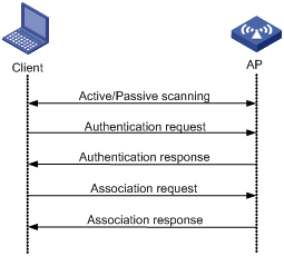
Scanning
Wireless clients use active scanning and passive scanning to obtain information about surrounding wireless networks.
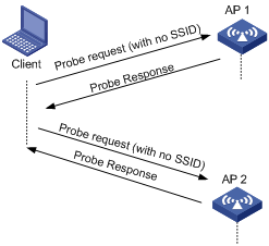
· Active scanning
A wireless client periodically sends probe request frames and obtains wireless network information from received probe response frames. Active scanning includes the following modes:
¡ Active scanning without an SSID—The client periodically sends a probe request frame without an SSID on each of its supported channels. APs that receive the probe request send a probe response, which includes the available wireless network information. The client associates with the AP with the strongest signal. This mode enables the client to find the optimal wireless network.
Figure 2 Active scanning without an SSID
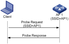
¡ Active scanning with an SSID—If the wireless client is configured to access a wireless network or has associated with a wireless network, the client periodically sends a probe request that carries the SSID of that wireless network. When the target AP receives the probe request, it sends a probe response. This mode enables the client to access a specified wireless network.
Figure 3 Active scanning with an SSID
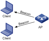
· Passive scanning
A wireless client listens to the beacon frames periodically sent by APs to discover surrounding wireless networks. Passive scanning is used when a client wants to save battery power. Typically, VoIP clients adopt passive scanning.
Figure 4 Passive scanning
Authentication
To secure wireless links, APs perform authentication on wireless clients. A wireless client must pass authentication before it can access a wireless network. 802.11 define two authentication methods: open system authentication and shared key authentication.
For more information about the authentication methods, see "Configuring WLAN security."
Association
To access a wireless network via an AP, a client must associate with that AP. After the client passes authentication on the AP, the client sends an association request to the AP. The AP checks the capability information in the association request to determine the capability supported by the wireless client, and sends an association response to notify the client of the association result. A client can associate with only one AP at a time, and an association process is always initiated by the client.
WLAN access configuration task list
|
Task |
Description |
|
Required. |
|
|
Setting the maximum number of concurrent join requests that an AC can process |
Optional. |
|
Required. |
|
|
Optional. |
|
|
Optional. |
|
|
Optional. |
|
|
Required. |
|
|
Optional. |
|
|
Required. |
|
|
Required. |
|
|
Optional. |
|
|
Optional. |
|
|
Optional. |
|
|
Optional. |
|
|
Optional. |
Enabling WLAN
You must enable WLAN before you can use WLAN services.
To enable WLAN:
|
Step |
Command |
Remarks |
|
1. Enter system view. |
system-view |
N/A |
|
2. Enable WLAN. |
wlan enable |
By default, WLAN is enabled. |
Setting the maximum number of concurrent join requests that an AC can process
|
Step |
Command |
Remarks |
|
1. Enter system view. |
system-view |
N/A |
|
2. Set the maximum number of concurrent join requests that an AC can process. |
wlan ap-concurrency-limit number |
By default, the number is 32. The value range is 1 to the maximum number of supported APs. The maximum number of supported APs of an AC varies by device model. For more information, see About the H3C Access Controllers Configuration Guide. |
Setting a country/region code
A country/region code determines the available wireless bands, channels, and power levels in the country where you deploy the WLAN.
Some ACs and fit APs have a fixed country/region code that cannot be modified. If an AC has a fixed country/region code, all the fit APs managed by the AC must use the AC's fixed country/region code. If a fit AP has a fixed country/region code, the fit AP can only use the fixed country/region code. If an AC and a fit AP each have a different fixed country/region code, they use the fixed country/region code of the fit AP.
To set a country/region code:
|
Step |
Command |
Remarks |
|
1. Enter system view. |
system-view |
N/A |
|
2. Set the global country/region code. |
wlan country-code code |
By default, the global country/region code is CN. |
|
3. Specify the AP name and its model number and enter AP template view. |
wlan ap ap-name model model-name [ id ap-id ] |
Specify the model name only when you create a new AP template. |
|
4. Set a country/region code for the AP. |
country-code code |
By default, the AP uses the global country/region code. If an AP is configured with a country/region code, the AP uses its own country/region code. If an AP is configured with a country/region code or has a fixed country/region code, changing the global country/region code does not affect the country/region code of the AP. |
Configuring auto AP
The auto AP feature enables APs to automatically associate with an AC. It can greatly reduce your workload when you deploy a wireless network with many APs.
Enabling auto AP
|
|
CAUTION: For security purposes, disable the auto-AP function after auto APs connect to the AC. |
You can enable auto AP in the following ways:
· Specify an auto-AP template and enable the auto-AP function.
After you create an auto-AP template by using the wlan ap command on the AC and enable the auto-AP function, the AC automatically associates with the APs of the model specified in the template, names the APs by using their MAC addresses, and assigns configurations in the template to APs. Clients can associate with auto APs but the administrator cannot change the configuration of auto APs.
Do not use the MAC address of an AP as the ap-name in the wlan ap ap-name model model-name command because the AC names auto APs by using their MAC addresses.
· Enable the auto-AP function.
After you enable the auto-AP function, the AC automatically associates with all APs and names the APs by using their MAC addresses. Clients can associate with the auto APs but the administrator cannot change the configuration of the auto APs.
You can enable an AP to connect to an AC by using one of the following methods:
· Configure the serial ID of the AP.
· Specify an auto-AP template.
· Enable the auto AP function.
The priorities of these configurations are in descending order. For example, if you configure the serial ID of an AP and enable the auto AP function, the AP comes online as a configured AP.
To enable auto AP:
|
Step |
Command |
Remarks |
|
1. Enter system view. |
system-view |
N/A |
|
2. Enable the auto-AP function. |
wlan auto-ap enable |
By default, the auto-AP function is disabled. |
|
3. Configure an auto-AP template. |
· Enter AP template view: · Enable auto AP serial ID configuration.: |
You must configure an auto-AP template when you want to connect the APs of a specific model. New settings for an auto-AP template only apply to APs that come online after the settings are configured. |
Configuring auto-AP authentication
The auto-AP authentication function enables you to control and manage auto APs. It only takes effect for auto APs. APs in this section refer to auto APs.
Auto-AP authentication has two modes:
· Local auto-AP authentication
In local authentication mode, the AC directly authenticates APs by serial ID or by MAC address, and uses an ACL specified by the wlan ap-authentication acl command to match APs.
Assume you adopt local authentication by serial ID. When an auto AP connects to the AC, the AC uses the serial ID of the AP to match ACL rules. If the serial ID matches a permit rule, the auto AP passes the authentication and connects to the AC. If the serial ID matches a deny rule, the auto AP fails the authentication and cannot connect to the AC. If the serial ID does not match any rule, the AP is an unauthenticated AP. The ACL can be manually configured or imported from a file.
· Remote auto-AP authentication
In remote authentication mode, the AC contacts a remote authentication server to authenticate unauthenticated APs. The AC uses the serial ID or MAC address of an unauthenticated AP as the username and password and sends them to the authentication server. If the remote authentication succeeds, the AC accepts the AP. If not, the AC denies the AP.
You can also use remote authentication to authenticate all auto APs.
The "unauthenticated AP" status is only available for local authentication. For remote authentication, the authentication result can only be "authentication failed" or "authentication succeeded."
|
|
NOTE: To re-authenticate an online auto AP, use the reset wlan ap unauthenticated command to log off the auto AP. |
To configure auto-AP authentication:
|
Step |
Command |
Remarks |
|
1. Enter system view. |
system-view |
N/A |
|
2. Enable an auto-AP authentication method. |
wlan ap-authentication method { mac-address | serial-id } |
Optional. By default, the AC authenticates APs by MAC address. |
|
3. Configure local auto-AP authentication. |
· Specify an ACL to authenticate auto APs: |
The specified ACL must have been configured. For more information about ACL, see QoS and ACL Configuration Guide. |
|
· Use ACL rules generated using the
specified file to authenticate auto APs: |
Optional. |
|
|
4. Configure remote auto-AP authentication. |
Specify an authentication domain and AAA scheme. |
For more information about authentication domain and AAA scheme, see Security Configuration Guide. |
|
Configure the username and password on the authentication server. |
The serial ID or MAC address of an auto AP is used as the username and password. |
|
|
Specify an
authentication domain: |
By default, no authentication domain is specified for auto-AP authentication. |
|
|
5. Enable auto-AP authentication. |
wlan ap-authentication enable |
By default, auto APs are not authenticated. |
Enabling unauthenticated auto APs to pass authentication and provide WLAN services
You can configure the AC to accept unauthenticated auto APs by using the wlan ap-authentication permit-unauthenticated command, but the auto APs cannot provide WLAN services. To enable them to pass authentication and provide WLAN services, execute the wlan ap-authentication accept command. After they pass authentication, the system generates corresponding ACL rules.
To enable unauthenticated auto APs to pass authentication and provide WLAN services:
|
Step |
Command |
Remarks |
|
1. Enter system view. |
system-view |
N/A |
|
2. Enable the AC to accept unauthenticated auto APs. |
wlan ap-authentication permit-unauthenticated |
Optional. By default, unauthenticated auto APs can connect to the AC but cannot provide WLAN services. |
|
3. Enable one or all unauthenticated auto APs to pass authentication and provide services and generate ACL rules. |
wlan ap-authentication { accept | reject } ap unauthenticated { all | name ap-name } |
Before you execute this command, use the wlan ap-authentication acl command to specify an ACL. ACL rules generated by this command are added to the specified ACL. This command also takes effect for authenticated online auto APs. |
Converting auto APs to configured APs
|
Step |
Command |
Remarks |
|
1. Enter system view. |
system-view |
N/A |
|
2. Convert an auto AP to a configured AP. |
wlan auto-ap persistent { all | name auto-ap-name [ new-ap-name ] } |
Use either approach. The wlan auto-persistent enable command takes effect only for auto APs that come online after the command is issued. To convert online auto APs to configured APs, you can only use the wlan auto-ap persistent command. |
|
3. Enable converting auto APs to configured APs. |
wlan auto-persistent enable |
Configuring AC and AP binding
If an AC is deployed in the public network to act as the NAT gateway for ACs in private networks, APs associate only with the public AC by default. Perform this task to specify an AC in the private network for an AP to balance the workloads. The public AC redirects AP association requests to the specified AC after the feature is configured.
To configure AC and AP binding:
|
Step |
Command |
Remarks |
|
4. Enter system view. |
system-view |
N/A |
|
5. Bind an AC to an AP. |
wlan ap-mac-address mac-address bas-ac-ip ip-address |
By default, no AC is bound to an AP. |
Specifying a backup VLAN interface for AC association
Perform this task to specify a VLAN interface that the AP uses to associate with the AC when the default VLAN interface VLAN-interface 1 is unavailable.
To specify a backup VLAN interface for AC association:
|
Step |
Command |
Remarks |
|
1. Enter system view. |
system-view |
N/A |
|
2. Specify a backup VLAN interface for AC association. |
wlan management-interface interface-type interface-number |
By default, an AP uses VLAN-interface 1 to associate with the AC. |
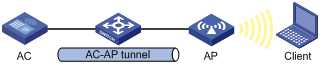
Configuring tunnel management
As shown in Figure 5, an AC and an AP establish a data tunnel to forward data packets and a control tunnel to forward control packets used for AP configuration and management. The AC can automatically configure and manage APs based on the information provided by the administrator.
Configuring parameters for an AP
Perform this task to configure parameters for an AP on the AC. The AC automatically assigns the parameters to the AP after the AP establishes a tunnel with it and enters Run state.
To configure parameters for an AP:
|
Step |
Command |
Remarks |
|
1. Enter system view. |
system-view |
N/A |
|
2. Set the discovery policy. |
wlan lwapp discovery-policy unicast |
Optional. By default, the tunnel discovery policy is broadcast. If you configure the discovery policy as unicast, broadcast discovery packets will be discarded. |
|
3. Specify the AP name and its model number and enter AP template view. |
wlan ap ap-name [ model model-name [ id ap-id ] ] |
Specify the model name only when you create an AP template. |
|
4. Set the serial ID of the AP or specify the auto AP. |
serial-id { text | auto } |
By default, no ID is specified for an AP. When you configure an auto AP, you must configure the wlan auto-ap enable command besides the serial-id auto command. |
|
5. Set a description for the AP. |
description text |
Optional. |
|
6. Enable the AP to send traps. |
trap enable |
Optional. |
|
7. Set the AP name. |
ap-name name |
Optional. By default, no AP name is configured. |
|
8. Set the maximum length of jumbo frames. |
jumboframe enable value |
By default, jumbo frame transmission is disabled. |
|
9. Enable the AP to respond to probe requests with null SSID from clients. |
broadcast-probe reply |
Optional. By default, the AP is enabled to respond to probe requests with null SSID from clients. |
|
10. Set the maximum idle time for connections between clients and the AP. |
client idle-timeout interval |
Optional. The default is 3600 seconds. |
|
11. Set the client keepalive interval. |
client keep-alive interval |
Optional. By default, the client keepalive function is disabled. |
|
12. Set an statistics report interval for the AP. |
statistics-interval interval |
Optional. By default, the statistics report interval is 50 seconds. |
|
13. Set the network access server (NAS)-PORT-ID for the AP. |
nas-port-id text |
Optional. By default, no NAS-PORT-ID is configured for an AP. |
|
14. Set the NAS-ID for the AP. |
nas-id nas-id |
Optional. By default, no NAS-ID is configured for an AP. |
|
15. Return to system view. |
quit |
N/A |
|
16. Configure a WLAN service template and enter service template view. |
wlan service-template service-template-number { clear | crypto } |
You cannot change an existing template to another type. |
|
17. Set the method for the AP to process packets from unknown clients. |
unknown-client { deauthenticate | drop } |
Optional. By default, when the AP receives a packet from an unknown client, it sends a deauthentication packet. |
Enabling AC-AP tunnel encryption with IPsec
Packets are transmitted over an AC-AP tunnel in plain text. To improve security, you can use IPsec to encrypt and authenticate control and data packets.
Follow these steps to configure AC-AP tunnel encryption with IPsec:
1. Configure the AP and AC to establish a tunnel and make sure the AP is in Run state.
2. Configure IPsec encryption in AP configuration view.
3. Reboot the AP to apply the new configuration.
4. Configure IPsec. For information about IPsec configuration, see Security Configuration Guide.
Follow these guidelines when you configure IPsec:
¡ Specify the security protocol, encapsulation mode, authentication algorithm, and encryption algorithm as ESP, tunnel, SHA1, and AES, respectively. Use IKEv1 to set up SAs, use the default security proposal, and adopt only the main IKE negotiation mode. For more information about IPsec commands, see Security Command Reference.
¡ You can configure an IPsec policy that uses IKE only by referencing an IPsec policy template.
¡ When you configure pre-shared key authentication for an IKE peer, the pre-shared key configured with the pre-shared-key command (the key on the AC) must be the same as that configured with the tunnel encryption ipsec pre-shared-key command (the key sent by the AC to the AP by using the AP provision function).
¡ When configuring IKE peers on an AC, you can use the remote-address command to specify the addresses or IP address ranges of APs that the AC accepts. If you do not configure IKE peers, the AC accepts negotiation requests sent by any AP. If multiple APs with different pre-shared keys need to establish IPsec tunnels with the AC, their IP address ranges cannot overlap. For more information about the remote-address command, see Security Command Reference.
¡ To make sure SAs between the AC and an AP are removed after the AP disconnects from the AC, perform the following tasks:
- Configure the Dead Peer Detection (DPD) function.
- Configure the ISAKMP SA keepalive interval by using the ike sa keepalive-timer interval command.
- Configure the ISAKMP SA keepalive timeout by using the ike sa keepalive-timer timeout command.
- Enable invalid security parameter index (SPI) recovery by using the ipsec invalid-spi-recovery enable command.
5. Apply the IPsec policy to the target VLAN interface.
The following table only shows the IPsec encryption configuration in AP configuration view:
|
Step |
Command |
Remarks |
|
1. Enter system view. |
system-view |
N/A |
|
2. Enter AP template view. |
wlan ap ap-name [ model model-name [ id ap-id ] ] |
Specify the model name only when you create an AP template. |
|
3. Enter AP configuration view. |
provision |
N/A |
|
4. Configure the AP to use IPsec to encrypt the control tunnel. |
tunnel encryption ipsec pre-shared-key { cipher | simple } key |
By default, the AP does not encrypt the control tunnel. |
|
5. Enable the AP to use IPsec to encrypt the data tunnel. |
data-tunnel encryption enable |
Optional. By default, the AP does not encrypt the data tunnel. |
|
6. Save the configuration to the wlan_ap_cfg.wcfg file of the specified AP. |
save wlan ap provision { all | name ap-name } |
This command takes effect only for APs in Run state. |
For more information about the tunnel encryption ipsec pre-shared-key, data-tunnel encryption enable, and save wlan ap provision { all | name ap-name } commands, see WLAN Command Reference.
Setting the echo interval for an AP
The AP sends echo requests to the AC at the echo interval, and the AC responds to echo requests by sending echo responses. The AC or AP tears down the tunnel if the AC does not receive an echo request from the AP or the AP does not receive an echo response from the AC within three times the echo interval.
To set the echo interval:
|
Step |
Command |
Remarks |
|
1. Enter system view. |
system-view |
N/A |
|
2. Enter AP template view. |
wlan ap ap-name [ model model-name [ id ap-id ] ] |
N/A |
|
3. Set the interval at which the AP sends echo requests. |
echo-interval interval |
Optional. By default, the echo interval is 10 seconds. |
Managing AC-AP tunnels
An AP terminates the AC-AP tunnel if it fails to receive echo responses for a period of time or if uplink retransmission fails. To prevent APs from going offline frequently, you can disable the echo mechanism or enable AP's insensitivity against uplink retransmission failures.
Managing AC-AP tunnels in AP template view
|
Step |
Command |
Remarks |
|
1. Enter system view. |
system-view |
N/A |
|
2. Enter AP template view. |
wlan ap ap-name [ model model-name [ id ap-id ] ] |
N/A |
|
3. Disable the echo mechanism between AP and AC. |
tunnel key-update disable |
By default, the echo mechanism between AP and AC is enabled. |
|
4. Configure the AP to not terminate the AP-AC tunnel upon uplink retransmission failures. |
tunnel uplink-retransmit-insensitive enable |
By default, an AP terminates the AP-AC tunnel when uplink retransmission fails. |
Managing AC-AP tunnels in AP group view
|
Step |
Command |
Remarks |
|
1. Enter system view. |
system-view |
N/A |
|
2. Enter AP group view. |
wlan ap-group group-name |
By default, all APs are added into a default AP group named default_group. |
|
3. Disable the echo mechanism between AP and AC. |
tunnel key-update disable |
By default, the echo mechanism between AP and AC is enabled. |
|
4. Configure the AP to not terminate the AP-AC tunnel upon uplink retransmission failures. |
tunnel uplink-retransmit-insensitive enable |
By default, an AP terminates the AP-AC tunnel when uplink retransmission fails. |
Managing APs
Specifying a configuration file for an AP
After you specify a configuration file for an AP, the AP downloads the configuration file from the AC each time it associates with the AC and enters Run state.
To specify a configuration file for an AP:
|
Step |
Command |
Remarks |
|
1. Enter system view. |
system-view |
N/A |
|
2. Enter AP template view. |
wlan ap ap-name [ model model-name [ id ap-id ] ] |
Specify the model name only when you create an AP template. |
|
3. Specify a configuration file for the AP. |
map-configuration filename |
Optional. By default, no configuration file is specified for an AP. The commands in the configuration file must be in their complete form. |
Renaming an AP
|
Step |
Command |
Remarks |
|
1. Enter system view. |
system-view |
N/A |
|
2. Rename an AP. |
wlan rename-ap ap-name new-ap-name |
You cannot change the name of an auto AP before you convert it to a configured AP. |
Configuring AP traffic protection
Configure AP traffic protection to avoid frequent AP reboots caused by traffic that exceeds the AP's capability.
To configure AP traffic protection:
|
Step |
Command |
Remarks |
|
1. Enter system view. |
system-view |
N/A |
|
2. Enter AP template view. |
wlan ap ap-name [ model model-name [ id ap-id ] ] |
Specify the model name only when you create an AP template. |
|
3. Set the CIR for packets sent from AC to AP. |
cir committed-information-rate [ cbs committed-burst-size ] |
Optional. By default, no CIR is set for packets sent from AC to AP. |
Enabling the AC to accept APs with a different software version
By default, the AC accepts only the APs that use the same software version as it. Perform this task if you want the AC to accept APs with a different software version.
To enable the AC to accept APs with a different software version:
|
Step |
Command |
Remarks |
|
1. Enter system view. |
system-view |
N/A |
|
2. Enable the AC to accept APs with the specified software version. |
wlan apdb model-name hardware-version software-version |
Optional. By default, a fit AP must use the same software version as the AC. If you set the hardware version to Ver.A, the AC ignores hardware versions of APs with the specified software version. |
Upgrading APs
Only LWAPP tunnels support AP version upgrade in different views.
An improper AP version can cause network problems when you upgrade versions for a large amount of APs at one time. To avoid the problem, you can upgrade a single AP, a group of APs, and all APs as needed.
The version upgrade configuration priorities in system view, AP group view, and AP template view are in ascending order. If this function is not configured in a view, configuration in the view with a lower priority is used.
If the version upgrade function is disabled, the AP and the AC establish a tunnel with each other without checking their versions.
If the version upgrade function is enabled, the AC checks the AP's version before establishing a tunnel. If their versions are different, the AP downloads a new version from the AC and restarts.
|
|
NOTE: If you enable the version upgrade function on the AC after an AC-AP tunnel is established, restart the AP manually so that the AP can automatically download a new version from the AC. |
Upgrading all APs
|
Step |
Command |
Remarks |
|
1. Enter system view. |
system-view |
N/A |
|
2. Enable or disable the AP version upgrade function for all APs. |
wlan ap-firmware-update { disable | enable } |
Optional. By default, version upgrade for all APs is enabled. |
|
3. Return to user view. |
quit |
N/A |
|
4. Reset the AP. |
reset wlan ap { all | name ap-name | unauthenticated } |
Optional. |
Upgrading a group of APs
To batch upgrade versions for multiple APs, add these APs into an AP group, and configure the AP version upgrade function in AP group view.
To upgrade a group of APs:
|
Step |
Command |
Remarks |
|
1. Enter system view. |
system-view |
N/A |
|
2. Create an AP group and enter AP group view. |
wlan ap-group group-name |
Optional. By default, all APs are added into a default AP group named default_group. |
|
3. Enable or disable the AP version upgrade function. |
firmware-update { disable | enable } |
Optional. By default, version upgrade for a group of APs is enabled. |
|
4. Return to user view. |
return |
N/A |
|
5. Reset all APs in the AP group. |
reset wlan ap ap-group group-name |
Optional. |
Upgrading a single AP
|
Step |
Command |
Remarks |
|
1. Enter system view. |
system-view |
N/A |
|
2. Create an AP template. |
wlan ap ap-name [ model model-name [ id ap-id ] ] |
Specify the model name when a template is created. |
|
3. Enable or disable the AP version upgrade function. |
firmware-update { disable | enable } |
Optional. By default, version upgrade for a single AP is enabled. |
|
4. Return to user view. |
return |
N/A |
|
5. Reset the specified AP. |
reset wlan ap name ap-name |
Optional. |
Configuring a WLAN service template
Creating a service template and setting an SSID
|
Step |
Command |
Remarks |
|
1. Enter system view. |
system-view |
N/A |
|
2. Create a WLAN service template and enter WLAN service template view. |
wlan service-template service-template-number { clear | crypto } |
You cannot change an existing service template to another type. You can create multiple service templates and specify different SSIDs or specify the same SSID for different service templates to enable one SSID to provide different access services. |
|
3. Set the service set identifier. |
ssid ssid-name |
N/A |
|
4. Set a description for the template. |
description string |
Optional. By default, no description is configured for the template. A description identifies a service template to avoid misconfiguration of SSIDs when you configure the same SSID for different service templates. |
|
5. Disable the advertising of SSID in beacon frames. |
beacon ssid-hide |
Optional. By default, the SSID is advertised in beacon frames. |
Configuring the country code to be carried in beacon frames
|
Step |
Command |
Remarks |
|
1. Enter system view. |
system-view |
N/A |
|
2. Enter WLAN service template view. |
wlan service-template service-template-number { clear | crypto } |
You cannot change an existing service template to another type. |
|
3. Configure whether beacon frames carry the country code and specify the operating environment. |
beacon country-code-ie { disable | enable { any | indoor | outdoor } } |
By default, beacon frames carry the country code and the operating environment is indoor. |
Enabling an authentication method
|
Step |
Command |
Remarks |
|
1. Enter system view. |
system-view |
N/A |
|
2. Enter WLAN service template view. |
wlan service-template service-template-number { clear | crypto } |
You cannot change an existing service template to another type. |
|
3. Enable the authentication method. |
authentication-method { open-system | shared-key } |
By default, open system authentication is used. For more information about the command, see WLAN Command Reference. |
Binding a WLAN-ESS interface to the service template
|
Step |
Command |
Remarks |
|
1. Enter system view. |
system-view |
N/A |
|
2. Create a WLAN service template and enter WLAN service template view. |
wlan service-template service-template-number { clear | crypto } |
You cannot change an existing service template to another type. |
|
3. Bind the WLAN-ESS interface to the service template. |
bind wlan-ess interface-index |
By default, no interface is bound to the service template. |
Configuring a forwarding mode
WLAN supports the following forwarding modes:
· Centralized forwarding—The AC performs data forwarding. Centralized forwarding comprises 802.3 centralized forwarding and 802.11 centralized forwarding. With 802.3 centralized forwarding, APs change incoming 802.11 frames to 802.3 frames and tunnel the 802.3 frames to the AC. With 802.11 centralized forwarding, APs directly tunnel incoming 802.11 frames to the AC.
· Local forwarding—APs directly forward data frames. The AC still performs authentication on clients. This forwarding mode reduces the workload of the AC and retains the security and management advantages of the AC/fit AP architecture.
· Policy-based forwarding—Based on the forwarding policy that matches the packets from clients, the AC chooses centralized forwarding mode or local forwarding mode. This forwarding mode reduces the workload of the AC. It only takes effect on packets sent by clients.
Configuring the centralized forwarding mode
|
Step |
Command |
Remarks |
|
1. Enter system view. |
system-view |
N/A |
|
2. Create a WLAN service template and enter WLAN service template view. |
wlan service-template service-template-number { clear | crypto } |
You cannot change an existing service template to another type. |
|
3. Enable the centralized forwarding mode. |
client remote-forwarding format { dot3 | dot11 } |
Optional. By default, data frames are encapsulated in 802.11 format and forwarded by the AC. This command only applies to a CAPWAP tunnel. For an LWAPP tunnel, data frames can only be encapsulated in 802.11 format. |
Configuring the local forwarding mode
|
Step |
Command |
Remarks |
|
1. Enter system view. |
system-view |
N/A |
|
2. Create a WLAN service template and enter WLAN service template view. |
wlan service-template service-template-number { clear | crypto } |
You cannot change an existing service template to another type. |
|
3. Enable the local forwarding mode. |
client forwarding-mode local [ vlan vlan-id-list ] |
By default, an AP forwards client data frames to the AC for centralized forwarding. |
Configuring the policy-based forwarding mode
If the AC adopts the local authentication mode, it also uses the local forwarding mode. Configuration of policed-based forwarding mode is invalid. For more information about authentication modes, see "Configuring client authentication."
Before you can apply a forwarding policy, create a forwarding policy and specify forwarding rules. The AC sorts ACL rules in ascending order of rule ID. A rule with a lower ID is matched before a rule with a higher ID. If a match is found, the AC forwards the packet according to this rule. If no match is found, or no rule is configured, the AC adopts the centralized forwarding mode by default.
The AC ignores the permit and deny statements when matching ACL rules, and only uses them for packet classification.
|
|
NOTE: When you configure the policy-based forwarding mode, do not deploy the AC and the AP in the same Layer 2 network as a best practice. |
Table 1 Supported ACL category
|
Category |
Match criteria |
|
|
IPv4 basic ACL |
Source IPv4 address |
|
|
IPv6 basic ACL |
Source IPv6 address |
|
|
IPv4 advanced ACL IPv6 advanced ACL |
IP |
Source and destination IP addresses |
|
TCP and UDP |
Source and destination port numbers |
|
|
ICMP |
Message type and message code of specified ICMP packets |
|
|
Ethernet frame header ACL |
Source and destination MAC addresses |
|
The forwarding modes can be applied to a user profile or service template:
· User profile—If a client passes 802.1X authentication, the authentication server sends the user profile name used by the client to the AP. Then the AP obtains the forwarding mode applied to the user profile. You need to create and enable the user profile on the AC first. If you configure a QoS policy in the user profile at the same time, and the packets match both the QoS policy and the forwarding mode, the QoS policy enjoys a higher priority.
· Service template—Clients associated with the AP adopt the forwarding mode in the service template.
If you configure different forwarding modes in the user profile and the service template, the forwarding mode in the user profile has a higher priority.
The forwarding mode takes effect only when applied to the AP, so you need to use the map-configuration command to download the configuration file from the AC to the AP. The configuration file must contain ACL numbers and ACL rules. To apply the forwarding mode to the user profile, you must include user profile configurations in the configuration file.
To configure policy-based forwarding:
|
Step |
Command |
Remarks |
|
1. Enter system view. |
system-view |
N/A |
|
2. Create a forwarding policy and enter forwarding policy view. |
wlan forwarding-policy policy-name |
By default, no forwarding policy exists. |
|
3. Configure forwarding rules. |
classifier acl { acl-number | ipv6 acl6-number } behavior { local | remote } |
By default, no forwarding rule is configured. |
|
4. Return to system view. |
quit |
N/A |
|
5. Create a WLAN service template. |
wlan service-template service-template-number { clear | crypto } |
You cannot change an existing service template to another type. |
|
6. Enable the policy-based forwarding mode and apply it to the service template. |
client forwarding-mode policy-based [ policy-name ] |
By default, the centralized forwarding mode is used. This command is required no matter whether you apply the mode to the user profile or the service template. |
Enabling centralized forwarding for client DHCP packets
In portal authentication, an AC identifies portal clients by their IP addresses. However, when central authentication and local forwarding are enabled, the DHCP server might assign the same IP address to clients in different LANs. To resolve the problem, you can use this feature to enable the AC to forward DHCP packets from clients when data packets are forwarded by APs.
To enable centralized forwarding for client DHCP packets:
|
Step |
Command |
Remarks |
|
1. Enter system view. |
system-view |
N/A |
|
2. Configure a WLAN service template. |
wlan service-template service-template-number { clear | crypto } |
You cannot change an existing service template to another type. |
|
3. Enable centralized forwarding for client DHCP packets. |
client dhcp-server centralized |
By default, the forwarding mode for client DHCP packets is the same as data packets. |
Configuring client authentication
WLAN access supports the following client authentication modes :
· Central—The AC authenticates clients. In central authentication mode, the data forwarding mode is determined by the client forwarding-mode local command. If the connection between AC and AP fails, logging off clients associated with the AP depends on the hybrid-remote-ap enable command. For more information about this command, see "Configuring a remote AP ."
· Local—The AP authenticates clients. In this mode, the AP directly forwards data frames from clients. If the connection to the AC fails, the AP does not log off locally authenticated clients and accepts new clients after they pass local authentication.
· Backup—The AC authenticates clients. When the AC-AP connection fails, the AP deletes all authentication information, authenticates new clients, and performs local forwarding. If remote AP is enabled, when the AP re-establishes a connection with the AC, the AP logs off all clients and the AC re-authenticates clients. The clients can associate with the AP only after they pass the authentication. If remote AP is disabled, when the AC-AP connection fails, the clients can associate with the AP only when the AC-AP connection recovers and the clients pass the authentication by the AC.
Configuration guidelines
Follow these guidelines when you configure client authentication:
· Portal authentication is not supported.
· Locally authenticated clients do not support roaming, or client information backup configured by the wlan backup-client enable command.
· You can execute the reset wlan client command on the AC to log off locally authenticated clients.
· For local authentication and backup authentication, do not modify the configuration on the AC if the AC and AP are disconnected. The AC checks the configuration after the connection recovers. If you change the configuration, the AC might log off online clients because of inconsistent configurations.
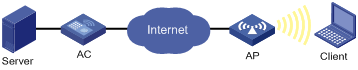
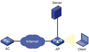
Networking modes
For local authentication, you can use the following networking modes if an authentication server is needed. The networking mode shown in Figure 7 is recommended. In this mode, online clients are not logged off when the connection between AP and AC fails because the authentication server is deployed at the AP side.
Figure 6 Network diagram
Configuration prerequisites
· Use the hybrid-remote-ap enable command to enable the remote AP function before you configure the backup or local authentication mode.
· If the clients use 802.1X or MAC authentication, you need to edit the configuration file of the AP and then use the map-configuration command to download the configuration file to the AP. The configuration file of the AP must contain the following contents:
¡ If clients use local 802.1X or local MAC authentication, the configuration file must contain port security, ISP domain, and local user configurations.
¡ If clients use remote 802.1X or remote MAC authentication, the configuration file must contain port security, ISP domain, and RADIUS scheme configurations.
Configuration procedure
|
Step |
Command |
Remarks |
|
1. Enter system view. |
system-view |
N/A |
|
2. Create a WLAN service template and enter WLAN service template view. |
wlan service-template service-template-number { clear | crypto } |
N/A |
|
3. Set an authentication mode. |
authentication-mode { backup | local } |
By default, central authentication is used. The AC authenticates clients. |
Setting the maximum number of associated clients
|
Step |
Command |
Remarks |
|
1. Enter system view. |
system-view |
N/A |
|
2. Create a WLAN service template and enter WLAN service template view. |
wlan service-template service-template-number { clear | crypto } |
You cannot change an existing service template to another type. |
|
3. Set the maximum number of clients allowed to associate with a radio. |
client max-count max-number |
The default is 64. |
Configuring beacon measurement
Beacon measurement, defined by 802.11k, provides a mechanism for APs and clients to measure the available radio resources. When this function is enabled, an AP periodically sends beacon requests to clients. Clients respond with beacon reports to inform the AP of the beacon measurement information they have collected.
The beacon measurement function supports the following measure modes:
· Active—Enables the active beacon measurement mode. In this mode, the AP sends a beacon measurement request to a client. Upon receiving the request, the client broadcasts probe requests on all supported channels, sets a measurement duration timer, and, at the end of the measurement duration, compiles all received beacons and probe responses into a measurement report.
· Beacon-table—Enables the beacon-table beacon measurement mode. In this mode, the AP sends a beacon measurement request to a client. Upon receiving the request, the client measures beacons and returns a report to the AP. The report contains all beacon information stored on the client.. The client does not perform any additional measurements.
· Passive—Enables the passive beacon measurement mode. In this mode, the AP sends a beacon measurement request to a client. Upon receiving the request, the client sets a measurement duration timer, and, at the end of the measurement duration, compiles all received beacons and probe responses into a measurement report.
|
|
NOTE: This function is only applicable to clients supporting the 802.11k protocol. |
To configure beacon measurement:
|
Step |
Command |
Remarks |
|
1. Enter system view. |
system-view |
N/A |
|
2. Create a WLAN service template and enter WLAN service template view. |
wlan service-template service-template-number { clear | crypto } |
You cannot change an existing service template to another type. |
|
3. Enable the beacon measurement function. |
beacon-measurement enable |
By default, this function is disabled. |
|
4. Set the beacon measurement mode. |
beacon-measurement type { active | beacon-table | passive } |
Optional. By default, the beacon-table bacon measurement mode is used. |
|
5. Set the interval at which the AP sends beacon request to clients. |
beacon-measurement interval interval |
Optional. By default, the interval is 60 seconds. |
Enabling fast association
|
Step |
Command |
Remarks |
|
1. Enter system view. |
system-view |
N/A |
|
2. Create a WLAN service template and enter WLAN service template view. |
wlan service-template service-template-number { clear | crypto } |
You cannot change an existing service template to another type. |
|
3. Enable fast association. |
fast-association enable |
By default, fast association is disabled. When this function is enabled, the AP does not perform band navigation or load balancing calculation for clients bound to the SSID. |
Configuring the client cache aging time
|
Step |
Command |
Remarks |
|
1. Enter system view. |
system-view |
N/A |
|
2. Create a WLAN service template and enter WLAN service template view. |
wlan service-template service-template-number { clear | crypto } |
You cannot change an existing service template to another type. |
|
3. Set the aging time for the client cache. |
client cache aging-time aging-time |
Optional. By default, the aging time is 180 seconds. |
Configuring A-MPDUs
|
Step |
Command |
Remarks |
|
1. Enter system view. |
system-view |
N/A |
|
2. Enter service template view. |
wlan service-template service-template-number { clear | crypto } |
You cannot change an existing service template to another type. |
|
3. Set the maximum number of MPDUs that can be aggregated into an A-MPDU. |
a-mpdu { 11ac | 11n | all } { rx | tx } packet-number number |
The default value varies by device model. |
|
4. Set the maximum length of an A-MPDU. |
a-mpdu { 11ac | 11n } packet-length-exponent exponent |
The default value varies by device model. |
Enabling a service template
|
Step |
Command |
Remarks |
|
1. Enter system view. |
system-view |
N/A |
|
2. Create a WLAN service template and enter WLAN service template view. |
wlan service-template service-template-number { clear | crypto } |
You cannot change an existing service template to another type. |
|
3. Enable the service template. |
service-template enable |
By default, the service template is disabled. |
Configuring radio parameters
Configuring basic radio parameters
|
Step |
Command |
Remarks |
|
1. Enter system view. |
system-view |
N/A |
|
2. Enter AP template view. |
wlan ap ap-name [ model model-name [ id ap-id ] ] |
Specify the model name only when you create an AP template. |
|
3. Enter radio view. |
radio radio-number [ type { dot11a | dot11an | dot11ac | dot11b | dot11g | dot11gn } ] |
The default varies by device. WLAN supports customizing the default radio type for AP models. |
|
4. Configure a channel. |
· Specify a channel for the radio: · Set the channel mode to auto. In this mode, you can lock the current channel: a. channel auto b. channel lock |
Optional. By default, auto mode is enabled and no channel is locked. For more information about the commands, see WLAN Command Reference. |
|
5. Configure the radio power. |
· Set the maximum power: · Lock the current power, and set the maximum
power as the power after power selection: |
Optional. By default: · The maximum radio power varies by the country/region code, channel, AP model, radio type, and antenna type. If 802.11n is used, the maximum radio power also varies by the bandwidth mode. · The current power is not locked. For more information about the commands, see WLAN Command Reference. |
|
6. Set the type of preamble. |
preamble { long | short } |
Optional. By default, the short preamble is supported. Only 2.4-GHz radios support this function. |
|
7. Enable the ANI function. |
ani enable |
Optional. By default, ANI is enabled. |
|
8. Enable the green energy management function. |
green-energy-management enable |
Optional. By default, the green energy management function is disabled. This function is only applicable to APs that support 802.11n and that can transmit at least two spatial streams. |
|
9. Set the MIMO type for the radio. |
mimo { 1x1 | 2x2 | 3x3 } |
Optional. By default, the MIMO type is not configured. This function is only applicable to APs that support 802.11n and that can transmit at least two spatial streams. |
|
10. Set the antenna type. |
antenna type type |
Optional. The default setting for the command varies by the antenna model of the device. |
|
11. Configure the smart antenna. |
a. Enable the smart antenna: b. Configure a smart antenna policy: |
Optional. By default, the smart antenna is enabled. The smart antenna has the following functions: · Ensures fast and stable bandwidth for clients in the coverage of the AP. · Reduces interference between APs and clients, and avoids interference from non-wireless devices in a high-density wireless environment. The smart antenna is available only if you have configured the antenna type command. By default, the smart antenna policy is autosensing. The smart antenna policy takes effect only if you have enabled the smart antenna. |
|
12. Enable Space-timed Block-Coding (STBC). |
stbc enable |
Optional. By default, STBC is enabled. Enabling STBC improves the SNR of the receiver and data transmission reliability. STBC can be used for wireless access and mesh links. When you enable STBC on a mesh link, enable STBC on both the sender and receiver as a best practice. STBC takes effect only when the number of antennas on an AP is greater than the number of spatial streams corresponding to the rates used by the radio. For example, if the MCS is 8 and the corresponding spatial stream number is 2, STBC takes effect only when the AP has at least three antennas. |
|
13. Set the maximum distance that the radio can cover. |
distance distance |
Optional. By default, the radio can cover a maximum of 1 km (0.62 miles). |
|
14. Enable LDPC. |
ldpc enable |
Optional. By default, LDPC is disabled. |
|
15. Bind a radio policy to the current radio. |
radio-policy radio-policy-name |
Optional. By default, the default_rp radio policy is mapped to the current radio. The default radio policy default_rp cannot be modified. The radio policy must have been configured with the wlan radio-policy command. |
Configuring a radio policy
|
Step |
Command |
Remarks |
|
1. Enter system view. |
system-view |
N/A |
|
2. Create a radio policy and enter radio policy view. |
wlan radio-policy radio-policy-name |
By default, the default radio policy default_rp exists. |
|
3. Set the interval for sending beacon frames. |
beacon-interval interval |
Optional. By default, the beacon interval is 100 TUs. |
|
4. Set the DTIM counter. |
dtim counter |
Optional. By default, the DTIM counter is 1. |
|
5. Set the maximum length of packets that can be transmitted without fragmentation. |
fragment-threshold size |
Optional. By default, the fragment threshold is 2346 bytes. The specified fragment threshold must be an even number. |
|
6. Set the maximum number of retransmission attempts for frames larger than the RTS threshold. |
long-retry threshold count |
Optional. By default, the long retry threshold is 4. |
|
7. Set the maximum number of attempts to transmit a frame shorter than the RTS threshold. |
short-retry threshold count |
Optional. By default, the short retry threshold is 7. |
|
8. Set the interval for the AP to hold received packets. |
max-rx-duration interval |
Optional. By default, the interval is 2000 milliseconds. |
|
9. Set the maximum number of associated clients. |
client max-count max-number |
Optional. By default, the maximum number of associated clients is 64. |
|
10. Set the request to send (RTS) threshold length. |
rts-threshold size |
By default, the RTS threshold is 2346 bytes. |
|
11. Set a collision avoidance mechanism. |
protection-mode { cts-to-self | rts-cts } |
By default, the collision avoidance mechanism is CTS-to-Self. |
|
12. Return to system view. |
quit |
N/A |
|
13. Enter AP template view. |
wlan ap ap-name [ model model-name [ id ap-id ] ] |
Specify the model name only when you create an AP template. |
|
14. Enter radio view. |
radio radio-number [ type { dot11a | dot11an | dot11ac | dot11b | dot11g | dot11gn } ] |
The default setting varies by AP model. |
|
15. Bind a radio policy to the current radio. |
radio-policy radio-policy-name |
Optional. By default, the default_rp radio policy is bound to a radio. |
Enabling automatic creation of radio policies by the SNMP set operation
After you enable automatic creation of radio policies by the SNMP set operation, a radio policy is automatically created and bound to each radio of a new AP template created through SNMP.
To enable automatic creation of radio policies by the SNMP set operation:
|
Step |
Command |
Remarks |
|
1. Enter system view. |
system-view |
N/A |
|
2. Enable automatic creation of radio policies by the SNMP set operation. |
wlan radio-policy auto-create snmp |
Optional. By default, automatic creation of radio policies by the SNMP operation is disabled. |
Configuring 802.11n
As the next generation wireless LAN technology, 802.11n supports both 2.4GHz and 5GHz bands. It provides higher throughput by using the following methods:
· Increasing bandwidth: 802.11n can bond two adjacent 20-MHz channels together to form a 40-MHz channel. During data forwarding, the two 20-MHz channels can work separately with one acting as the primary channel and the other acting as the secondary channel or work together as a 40-MHz channel. This provides a simple way of doubling the data rate.
· Improving channel utilization by using the following functions:
¡ A-MPDU—Each A-MPDU uses only one PHY header to accommodate multiple MPDUs, reducing transmission overhead and the number of ACK frames.
¡ A-MSDU—Each A-MSDU accommodates multiple MSDU, reducing MAC header overhead and improving MAC layer forwarding efficiency.
¡ Short GI—Shortens the GI interval of 800 ns in 802.11a/g to 400 ns, increasing the rate by 10 percent.
To configure 802.11n:
|
Step |
Command |
Remarks |
|
1. Enter system view. |
system-view |
N/A |
|
2. Enter AP template view. |
wlan ap ap-name [ model model-name [ id ap-id ] ] |
Specify the model name only when you create an AP template. |
|
3. Enter radio view. |
radio radio-number type { dot11an | dot11gn } |
N/A |
|
4. Set the bandwidth mode for the radio. |
channel band-width { 20 | 40 [auto-switch] } |
Optional. By default, the channel bandwidths for the 802.11a/n radio and the 802.11g/n radio are 40 MHz and 20 MHz, respectively. When the channel bandwidth of the 802.11gn radio is 40 MHz, the automatic bandwidth switch function is disabled. To enable the function, use channel band-width 40 auto-switch command. |
|
5. Enable access permission only for 802.11n clients. |
client dot11n-only |
Optional. By default, an 802.11a/n radio permits both 802.11a and 802.11an clients to access, and an 802.11g/n radio permits both 802.11g and 802.11gn clients to access. |
|
6. Enable the short GI function. |
short-gi enable |
Optional. By default, the short GI function is enabled. |
|
7. Enable the A-MSDU function. |
a-msdu enable |
Optional. By default, the A-MSDU function is enabled. The device receives but does not send A-MSDUs. |
|
8. Enable the A-MPDU function. |
a-mpdu enable |
Optional. By default, the A-MPDU function is enabled. |
|
9. Enable the sFlow function. |
sflow enable |
Optional. By default, the sFlow function is enabled. For more information about sFlow, see Network Management and Monitoring Configuration Guide. |
|
10. Enable the radio. |
radio enable |
By default, the radio is disabled. Before enabling the radio, you must configure the MCS. For more information about MCS index and mandatory and supported 802.11n rates, see "Configuring WLAN RRM." |
Mapping a service template to the radio
|
Step |
Command |
Remarks |
|
1. Enter system view. |
system-view |
N/A |
|
2. Enter AP template view. |
wlan ap ap-name [ model model-name [ id ap-id ] ] |
Specify the model name only when you create an AP template. |
|
3. Enter radio view. |
radio radio-number [ type { dot11a | dot11an | dot11ac | dot11b | dot11g | dot11gn } ] |
The default setting of this command depends on the device model. |
|
4. Map a service template to the current radio. |
service-template service-template-number [ vlan-id vlan-id ] | [ vlan-pool vlan-pool-name ] [ nas-port-id nas-port-id | nas-id nas-id ] [ ssid-hide ] |
Optional. You can map multiple service templates to the current radio. By default, no mapping exists between a service template and a radio. |
Enabling a radio
|
Step |
Command |
Remarks |
|
1. Enter system view. |
system-view |
N/A |
|
2. Enable/disable WLAN radios. |
wlan radio { disable | enable } { all | dot11a | dot11ac | dot11an | dot11b | dot11g | dot11gn | radio-policy radio-policy-name } |
By default, no WLAN radio is enabled. |
|
3. Enter AP template view. |
wlan ap ap-name [ model model-name [ id ap-id ] ] |
Specify the model name only when you create an AP template. |
|
4. Enter radio view. |
radio radio-number [ type { dot11a | dot11an | dot11ac | dot11b | dot11g | dot11gn } ] |
The default setting of this command depends on the device model. |
|
5. Enable the radio. |
radio enable |
By default, the radio is disabled. |
Configuring 802.11ac
802.11ac bonds four 20-MHz channels together to form an 80-MHz channel to improve throughput. It also inherits the method of 802.11n to improve channel utilization.
To configure 802.11ac:
|
Step |
Command |
Remarks |
|
1. Enter system view. |
system-view |
N/A |
|
2. Enter AP template view. |
wlan ap ap-name [ model model-name [ id ap-id ] ] |
Specify the model name only when you create an AP template. |
|
3. Enter radio view. |
radio radio-number type dot11ac |
N/A |
|
4. Specify the bandwidth mode for the radio. |
channel band-width { 20 | 40 | 80 } |
Optional. By default, the 802.11ac radio operates in 80 MHz mode. |
|
5. Enable WLAN access for 802.11n and 802.11ac clients. |
client dot11n-only |
Optional. By default, an 802.11ac radio permits 802.11a, 802.11an and 802.11ac clients to access the WLAN. |
|
6. Enable WLAN access for only 802.11ac client. |
client dot11ac-only |
Optional. By default, an 802.11ac radio permits 802.11a, 802.11an and 802.11ac clients to access the WLAN. |
|
7. Enable the short GI function. |
short-gi enable |
Optional. By default, the short GI function is enabled. |
|
8. Enable the A-MSDU function. |
a-msdu enable |
Optional. By default, the A-MSDU function is enabled. The device receives but does not send A-MSDUs. |
|
9. Enable the A-MPDU function. |
a-mpdu enable |
Optional. By default, the A-MPDU function is enabled. |
|
10. Enable the radio. |
radio enable |
By default, the radio is disabled. Before enabling the radio, you must configure the number of spatial stream (NSS). For more information about basic NSS and mandatory and supported 802.11ac rates, see "Configuring WLAN RRM." |
|
|
NOTE: For more information about the basic number and supported number of spatial streams of 802.11ac, see "Configuring WLAN RRM." |
Configuring an AP group
This feature enables you to configure multiple APs in one operation to reduce configuration workload.
There is a default AP group named default_group. You cannot delete but can modify the default AP group. All APs created belong to the default AP group by default.
You can add APs with the same configurations or in the same subnet to the same AP group. The APs use the configuration of the AP group. If you add an auto AP template into a non-default AP group, the auto APs coming online through the template belong to the AP group. The auto APs use the configuration of the AP group to which the auto AP template belongs.
Typically, commands executed in AP group view apply to all APs in the group. If an AP fails to execute a command, the system displays error messages and other APs can still execute the command.
When you change the AP group of an AP, the AP restarts, and clears its configuration except the serial number. After the AP is added to the new AP group, the AP uses the configuration of the new AP group.
Creating an AP group
|
Step |
Command |
Remarks |
|
1. Enter system view. |
system-view |
N/A |
|
2. Create an AP group and enter its view. |
wlan ap-group group-name |
By default, a default group default_group exists. All APs belong to the default group. |
Configuring IP address match criteria for an AP group
Perform this task to manage APs by matching IP addresses.
Follow these guidelines when you configure IP address match criteria for an AP group:
· The IP address match criteria take effect when an AP requests to associate with the AC. Any change of the criteria does not affect associated APs.
· An AP that associates with the AC by matching IP address does not support VRRP even if it disassociates and then associates with the AC again. To enable the AP to support VRRP, manually add it to another AP group where the members are not in the same subnet as the AP.
· An AP (configured or auto) that has been manually added to an AP group is always in the group even if its IP address matches the subnet of another AP group.
· For an auto AP that is already in the default group default_group, if its IP address matches the subnet of a non-default AP group, the AC adds it to this AP group.
To configure IP address match criteria for an AP group:
|
Step |
Command |
Remarks |
|
1. Enter system view. |
system-view |
N/A |
|
2. Create an AP group and enter its view. |
wlan ap-group group-name |
By default, a default group default_group exists. All APs belong to the default group. |
|
3. Configure an IPv4 address match criterion for the AP group. |
if-match ip ip-address { mask-length | mask } |
Optional. By default, no IPv4 address match criteria are configured. |
|
4. Configure an IPv6 address match criterion for the AP group. |
if-match ipv6 { ipv6-address prefix-length | ipv6-address/prefix-length } |
Optional. By default, no IPv6 address match criteria are configured. |
Configuring an AP group
Follow these guidelines when you configure an AP group:
· You can configure APs one by one or add multiple APs into an AP group. The most recent configuration takes effect.
· The dot11a radio enable, dot11a radio-policy, dot11a service-template, dot11bg radio enable, dot11bg radio-policy, dot11bg service-template, and work-mode commands might fail on some APs in an AP group. For more information about these commands, see WLAN Command Reference.
To configure an AP group:
|
Step |
Command |
Remarks |
|
1. Enter system view. |
system-view |
N/A |
|
2. Create an AP group and enter AP group view. |
wlan ap-group group-name |
By default, a default AP group default_group exists and all APs belong to this group. The maximum number of AP groups depends on the device model. For more information, see About the H3C Access Controllers Configuration Guide. |
|
3. Configure a description for the AP group. |
description string |
Optional. By default, no description is configured for the AP group. |
|
4. Enable the AP to respond to probe requests with null SSID from clients. |
broadcast-probe reply |
Optional. By default, the AP is enabled to respond to probe requests with null SSID from clients. |
|
5. Set the maximum idle time for connections between clients and the AP. |
client idle-timeout interval |
Optional. The default is 3600 seconds. |
|
6. Set the client keepalive interval. |
client keep-alive interval |
Optional. By default, the client keepalive function is disabled. |
|
7. Configure the IP address for the backup AC. |
backup-ac { ip ipv4-address | ipv6 ipv6-address } |
Optional. By default, no backup AC IP address is configured. |
|
8. Set a country/region code for the AP. |
country-code code |
By default, the AP has no country/region code. |
|
9. Set the interval at which the AP sends echo requests. |
echo-interval interval |
Optional. By default, the echo interval is 10 seconds. |
|
10. Enabling the remote AP function for the AP. |
hybrid-remote-ap enable |
By default, the remote AP function is disabled. |
|
11. Specify a configuration file for the AP. |
map-configuration filename |
Optional. By default, no configuration file is specified for an AP. |
|
12. Set the AC connection priority for the AP. |
priority level priority |
Optional. By default, the AP connection priority is 4. |
|
13. Set the statistics report interval. |
statistics-interval interval |
Optional. By default, the statistics report interval is 50 seconds. |
|
14. Set the AP to operate in hybrid mode. |
device-detection enable |
Optional. By default, the AP operates in normal mode and only provides WLAN data services. For more information about the command, see WLAN Command Reference. |
|
15. Set the AP to operate in monitor mode. |
work-mode monitor |
Optional. By default, the AP operates in normal mode to provide WLAN data services. For more information about the command, see WLAN Command Reference. |
|
16. Enable sFlow on 5 GHz radios of APs in the AP group. |
dot11a sflow enable |
Optional. By default, the sFlow function is enabled for an AP group. For more information about sFlow, see Network Management and Monitoring Configuration Guide. |
|
17. Enable or disable the AP version upgrade function for a group of APs. |
firmware-update { disable | enable } |
Optional By default, version upgrade for a group of APs is enabled. |
|
18. Map a service template to the 5 GHz radios of APs in the AP group. |
dot11a service-template service-template-number [ vlan-id vlan-id | vlan-pool vlan-pool-name ] |
Optional. By default, no service template is configured for an AP group. |
|
19. Map a radio policy to the 5 GHz radios of APs in the AP group. |
dot11a radio-policy radio-policy-name |
Optional. By default, the 5 GHz radios of all APs in the AP group use the default radio policy default_rp. |
|
20. Enable the 5 GHz radios of APs in the AP group. |
dot11a radio enable |
Optional. By default, the 5 GHz radios of APs in an AP group are disabled. |
|
21. Enable sFlow on 2.4 GHz radios of APs in the AP group. |
dot11bg sflow enable |
Optional. By default, the sFlow function is enabled for an AP group. For more information about sFlow, see Network Management and Monitoring Configuration Guide. |
|
22. Map a service template to the 2.4 GHz radios of APs in the AP group. |
dot11bg service-template service-template-number [ vlan-id vlan-id | vlan-pool vlan-pool-name ] |
Optional. By default, no service template is configured for an AP group. |
|
23. Map a radio policy to the 2.45 GHz radios of APs in the AP group. |
dot11bg radio-policy radio-policy-name |
Optional. By default, the 2.4 GHz radios of all APs in the AP group use the default radio policy default_rp. |
|
24. Enable the 2.4 GHz radios of APs in the AP group. |
dot11bg radio enable |
Optional. By default, the 2.4 GHz radios of APs in an AP group are disabled. |
Adding an AP to an AP group
You use either approach to add an AP to an AP group.
Method 1:
|
Step |
Command |
Remarks |
|
1. Enter system view. |
system-view |
N/A |
|
2. Create an AP group and enter AP group view. |
wlan ap-group group-name |
By default, an AP group named default_group exists and all APs are in this group. |
|
3. Add APs to the AP group. |
ap template-name-list |
By default, no APs exist in a new AP group created with the wlan ap-group command. |
Method 2:
|
Step |
Command |
Remarks |
|
1. Enter system view. |
system-view |
N/A |
|
2. Enter AP template view. |
wlan ap ap-name [ model model-name [ id ap-id ] ] |
Specify the model name only when you create an AP template. |
|
3. Add the AP to the AP group. |
ap-group group-name |
By default, all APs are in the default AP group default_group. |
Setting the statistics report interval
|
Step |
Command |
Remarks |
|
1. Enter system view. |
system-view |
N/A |
|
2. Enter AP template view. |
wlan ap ap-name [ model model-name [ id ap-id ] ] |
Specify the model name only when you create an AP template. |
|
3. Set the statistics report interval. |
statistics-interval interval |
The default interval is 50 seconds. |
Setting the memory utilization threshold for an AP
|
Step |
Command |
Remarks |
|
1. Enter system view. |
system-view |
N/A |
|
2. Enter AP template view. |
wlan ap ap-name [ model model-name [ id ap-id ] ] |
Specify the model name only when you create an AP template. |
|
3. Set the memory utilization threshold. |
memory-usage threshold integer |
The default value is 90. When the threshold is exceeded, the AC sends alarms. |
Restoring the factory default settings of APs
|
Step |
Command |
Remarks |
|
1. Enter system view. |
system-view |
N/A |
|
2. Restore the factory default settings of one or all APs. |
wlan ap-execute { all | name ap-name } conversion-to-factory |
By default, the default settings are not restored for any AP. Terminate the physical connection between an AP and the AC after executing the command. Then the configuration takes effect only when the AP is rebooted. |
Enabling automatic heating for an outdoor AP
The automatic heating function enables an outdoor AP to operate properly when the operating temperature is too low.
To enable the automatic heating function:
|
Step |
Command |
Remarks |
|
1. Enter system view. |
system-view |
N/A |
|
2. Enable the automatic heating function. |
wlan ap-execute { all | name ap-name } heatfilm { disable | enable } |
By default, the automatic heating function is disabled. |
Shutting down all LEDs on APs
|
Step |
Command |
Remarks |
|
1. Enter system view. |
system-view |
N/A |
|
2. Enter AP template view. |
wlan ap ap-name [ model model-name [ id ap-id ] ] |
Specify the model name only when you create an AP template. |
|
3. Shut down all LEDs on all online APs using the current AP template. |
shut-all-led enable |
By default, all LEDs on all the online APs of the current AP template light based on AP status. |
Enabling SNMP traps for the WLAN module
This task enables the WLAN module to generate level-4 warning messages and send them to the information center of the device. You can configure the output channels and destinations for the trap messages. For more information, see Network Management and Monitoring Configuration Guide.
To enable SNMP traps for the WLAN module:
|
Step |
Command |
Remarks |
|
1. Enter system view. |
system-view |
N/A |
|
2. Enable SNMP traps for the WLAN module. |
snmp-agent trap enable wlan |
Optional. By default, SNMP traps for the WLAN module is enabled. |
|
3. Specify the threshold percentage for sending SNMP traps. |
wlan trap ap-number threshold value |
Optional. The threshold percentage for sending SNMP traps is 100. |
|
4. Enable the AC to send SNMP traps to the NMS when the number of concurrent online APs reaches or drops below the upper limit. |
snmp-agent trap enable wlan { above-ap-number | below-ap-number } |
Optional. By default, the AC sends SNMP traps to the NMS when the number of concurrent online APs reaches or drops below the upper limit. For more information about the snmp-agent trap enable wlan command, see Network Management and Monitoring Command Reference. |
Configuring client IP address monitoring
This task monitors IPv4 address changes of wireless clients.
The AC monitors the IP address of a client as follows:
· If the client obtains an IP address through DHCP:
a. The AP obtains the IP address of the client from the DHCPv4 packets transferred between the client and the DHCP server.
b. The AP sends the IP address entry to the AC.
c. The AC prints Syslog messages.
· If the client is manually configured a static IP address:
a. The AP resolves ARP packets from the client to obtain its IP address.
b. The AP sends the IP address entry to the AC.
c. The AC prints Syslog messages.
Follow these guidelines when you configure client IP address monitoring:
· If the AP fails to obtain an IP address of a clients, the AC does not print Syslog messages.
· If you manually modify the IP address of a client that has been associated with the AP, the AC prints Syslog messages.
· For the same client, the IP address assigned by the DHCP server has a higher priority. For example, a client obtains an IP address from the DHCP server and then associates with the AC. If you manually enter an IP address the same as the IP address obtained from the DHCP server, the AC considers this IP address as the one the client got from the DHCP server.
To configure client IP address monitoring:
|
Step |
Command |
Remarks |
|
1. Enter system view. |
system-view |
N/A |
|
2. Enable client IP address monitoring. |
wlan client learn-ipaddr enable |
By default, the client IP address monitoring function is disabled. You can use the display wlan client source binding command to display IP addresses of clients on the AC. (See Security Command Reference.) |
Configuring management packet statistics collection
|
Step |
Command |
Remarks |
|
1. Enter system view. |
system-view |
N/A |
|
2. Set the statistics collection interval. |
wlan statistics ap-interval ap-interval |
Optional. By default, the statistics collection interval is 60 seconds. |
|
3. Set the management packet alarm threshold. |
wlan statistics ap-threshold ap-threshold |
Optional. By default, the management packet alarm threshold is 1000. |
Displaying and maintaining WLAN access
|
Task |
Command |
Remarks |
|
Display the country/region code information for the AP. |
display wlan country-code ap { all | name ap-name } [ | { begin | exclude | include } regular-expression ] |
Available in any view. |
|
Display AP information. |
display wlan ap { all | name ap-name | unauthenticated } [ verbose ] [ | { begin | exclude | include } regular-expression ] |
Available in any view. |
|
Display AP address information. |
display wlan ap { all | name ap-name } address [ | { begin | exclude | include } regular-expression ] |
Available in any view. |
|
Display AP connection records. |
display wlan ap connection record { all | mac-address mac-address } [ | { begin | exclude | include } regular-expression ] |
Available in any view. |
|
Display radio information. |
display wlan ap { all | name ap-name } radio [ | { begin | exclude | include } regular-expression ] |
Available in any view. |
|
Display AP and AC binding relations. |
display wlan ap-mac-address [ mac-address ] |
Available in any view. |
|
Display the model information of a specified AP or all APs supported on the AC. |
display wlan ap-model { all | name ap-name } [ | { begin | exclude | include } regular-expression ] |
Available in any view. |
|
Display the reboot log information of an AP. |
display wlan ap reboot-log name ap-name [ | { begin | exclude | include } regular-expression ] |
Available in any view. |
|
Display forwarding policy information. |
display wlan forwarding-policy [ forwarding-policy-name ] [ | { begin | exclude | include } regular-expression ] |
Available in any view. |
|
Display WLAN radio policy information. |
display wlan radio-policy [ radio-policy-name ] [ | { begin | exclude | include } regular-expression ] |
Available in any view. |
|
Display WLAN service template information. |
display wlan service-template [ service-template-number ] [ | { begin | exclude | include } regular-expression ] |
Available in any view. |
|
Display AP connection statistics. |
display wlan statistics ap { all | name ap-name } connect-history [ | { begin | exclude | include } regular-expression ] [ verbose ] |
Available in any view. |
|
Display wireless client statistics. |
display wlan statistics client { all | mac-address mac-address } [ | { begin | exclude | include } regular-expression ] |
Available in any view. |
|
Display bridge statistics. |
display wlan client bridge [ ap ap-name [ radio radio-number ] ] [ verbose ] [ | { begin | exclude | include } regular-expression ] |
Available in any view. |
|
Display radio statistics. |
display wlan statistics radio [ ap ap-name ] [ | { begin | exclude | include } regular-expression ] |
Available in any view. |
|
Display AP load information. |
display wlan statistics radio [ ap ap-name ] load [ | { begin | exclude | include } regular-expression ] |
Available in any view. |
|
Display service template statistics. |
display wlan statistics service-template service-template-number [ | { begin | exclude | include } regular-expression ] |
Available in any view. |
|
Display the connection history for all APs bound to a service template. |
display wlan statistics service-template service-template-number connect-history [ | { begin | exclude | include } regular-expression ] |
Available in any view. |
|
Display WLAN client information. |
display wlan client { ap ap-name [ radio radio-number ] | mac-address mac-address | service-template service-template-number } [ verbose ] [ | { begin | exclude | include } regular-expression ] |
Available in any view. |
|
Display AP group information. |
display wlan ap-group [ group-name ] [ | { begin | exclude | include } regular-expression ] |
Available in any view. |
|
Display the status of APs after their settings are restored to factory defaults. |
display wlan ap-execute conversion-to-factory [ | { begin | exclude | include } regular-expression ] |
Available in any view. |
|
Display beacon reports sent by clients. |
display wlan client [ mac-address mac-address ] beacon-report [ | { begin | exclude | include } regular-expression ] |
Available in any view. |
|
Reset all APs in a specific AP group. |
reset wlan ap ap-group group-name |
Available in user view. |
|
Reset AP connections. |
reset wlan ap { all | name ap-name | unauthenticated } |
Available in user view. |
|
Clear AP connection records. |
reset wlan ap connection record { all | mac-address mac-address } |
Available in user view. |
|
Clear AP reboot logs. |
reset wlan ap reboot-log { all | name ap-name } |
Available in user view. |
|
Clear statistics of an AP or client. |
reset wlan statistics { ap { all | name ap-name } | client { all | mac-address mac-address } | radio [ ap-name ] } |
Available in user view. |
|
Cut off WLAN clients. |
reset wlan client { all | mac-address mac-address } |
Available in user view. |
|
RFPing a wireless client. |
wlan link-test mac-address |
Available in user view. You can use the wlan link-test command to perform a Radio Frequency Ping (RFPing) operation to a client. The operation results show information about signal strength and round trip time (RTT) between the AP and the client. |
Configuring a remote AP
Remote AP provides a wireless solution for remote branches and offices. It enables you to configure and control remote APs from the headquarters over the Internet without deploying an AC in each office or branch.
As shown in Figure 8, the AC manages the remote APs over the Internet. When the tunnel between an AP and the AC fails, the AP automatically enables local forwarding (despite whether or not local forwarding is configured on the AC) to provide wireless access for logged-on clients. It permits new clients. When the tunnel recovers, the AP automatically switches to centralized forwarding mode and logs off all online clients.
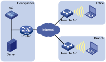
Follow these guidelines when you enable the remote AP function:
· The remote AP and mesh functions cannot be used simultaneously.
· Do not shut down all physical ports on the remote AP. Otherwise, the AP cannot perform local forwarding and logs off all online clients.
· If an AP establishes tunnels to both the primary AC and a backup AC, it uses the backup tunnel to provide wireless access for logged-on clients when the primary tunnel fails.
· Disable the online user handshake function for the service template that uses 802.1X authentication on the AP.
To enable the remote AP function:
|
Step |
Command |
Remarks |
|
1. Enter system view. |
system-view |
N/A |
|
2. Enter AP template view. |
wlan ap ap-name [ model model-name [ id ap-id ] ] |
Specify the model name only when you create an AP template. |
|
3. Enabling the remote AP function for the AP. |
hybrid-remote-ap enable |
By default, the remote AP function is disabled. |
Configuring WLAN access control
Configuring AP-based access control
Support for the AP group function depends on the device model. For more information, see About the H3C Access Controllers Configuration Guides.
Some wireless service providers need to control the access positions of clients. For example, as shown in Figure 9, the provider needs to connect wireless clients 1, 2 and 3 to the wired network through APs 1, 2, and 3, respectively. To achieve this, the provider could configure an AP group and then apply the AP group to a user profile.
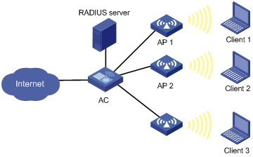
Configuring an AP group
|
Step |
Command |
Remarks |
|
1. Enter system view. |
system-view |
N/A |
|
2. Create an AP group and enter AP group view. |
wlan ap-group value |
N/A |
|
3. Add specified APs into the AP group. |
ap template-name-list |
By default, no AP is added. You can use this command repeatedly to add multiple APs, or to add up to 10 APs in one command line. A nonexistent AP can be added. |
|
4. Set a description for the AP group. |
description string |
Optional. By default, no description is configured for the AP group. |
Applying the AP group to a user profile
|
Step |
Command |
Remarks |
|
1. Enter system view. |
system-view |
N/A |
|
2. Enter user profile view. |
user-profile profile-name |
If the user profile does not exist, create it first. |
|
3. Apply the AP group to the user profile. |
wlan permit-ap-group value |
By default, no AP group is applied to the user profile. For more information about user profile, see Security Configuration Guide. |
|
4. Return to system view. |
quit |
N/A |
|
5. Enable the user profile. |
user-profile profile-name enable |
By default, the user profile is not enabled. The user profile must have the same name as the external group on the RADIUS server. To support roaming, all ACs in a mobility group must have the same profile name configured. |
Displaying and maintaining AP group
|
Command |
Remarks |
|
|
Display AP group information. |
display wlan ap-group [ group-id ] [ | { begin | exclude | include } regular-expression ] |
Available in any view. |
Configuring SSID-based access control
When a user wants to access a WLAN temporarily, the administrator can specify a permitted SSID in the corresponding user profile so that the user can only access the WLAN through the SSID.
To specify a permitted SSID:
|
Step |
Command |
Remarks |
|
||
|
1. Enter system view. |
system-view |
N/A |
|||
|
2. Enter user profile view. |
user-profile profile-name |
If the specified user profile does not exist, this command creates it and enters its view. |
|||
|
3. Set a permitted SSID. |
wlan permit-ssid ssid-name |
By default, no permitted SSID is specified, and users can access the WLAN without SSID limitation. |
|||
|
4. Return to system view. |
quit |
N/A |
|||
|
5. Enable the user profile. |
user-profile profile-name enable |
By default, the user profile is not enabled. The user profile needs to be enabled to take effect. For more information about user access control and user profile, see Security Configuration Guide. |
|||
WLAN access configuration examples
WLAN access configuration example
Network requirements
As shown in Figure 10, enable the client to access the internal network resources at any time. The manually entered serial ID of the AP is 210235A29G007C000020. The AP adopts 802.11an and provides plain-text wireless access service with SSID service1.

Configuration procedure
1. Configure the AC:
# Enable WLAN.
<AC> system-view
[AC] wlan enable
# Create a WLAN ESS interface.
<AC> system-view
[AC] interface WLAN-ESS 1
[AC-WLAN-ESS1] quit
# Create a clear-type WLAN service template, set the SSID of the service template to service, and bind the WLAN-ESS interface to this service template.
[AC] wlan service-template 1 clear
[AC-wlan-st-1] ssid service
[AC-wlan-st-1] bind WLAN-ESS 1
[AC-wlan-st-1] authentication-method open-system
[AC-wlan-st-1] client max-count 10
[AC-wlan-st-1] service-template enable
[AC-wlan-st-1] quit
# Configure a radio policy.
[AC] wlan radio-policy radpolicy1
[AC-wlan-rp-radpolicy1] beacon-interval 200
[AC-wlan-rp-radpolicy1] dtim 4
[AC-wlan-rp-radpolicy1] rts-threshold 2300
[AC-wlan-rp-radpolicy1] fragment-threshold 2200
[AC-wlan-rp-radpolicy1] short-retry threshold 6
[AC-wlan-rp-radpolicy1] long-retry threshold 5
[AC-wlan-rp-radpolicy1] max-rx-duration 500
# Create an AP template named ap1 and its model is WA3628i-AGN, and set the serial ID of the AP to 210235A29G007C000020.
[AC] wlan ap ap1 model WA3628i-AGN
[AC-wlan-ap-ap1] serial-id 210235A29G007C000020
[AC-wlan-ap-ap1] description L3office
# Set the radio type to dot11an, and channel to 161.
[AC-wlan-ap-ap1] radio 1 type dot11an
[AC-wlan-ap-ap1-radio-1] channel 161
# Bind radio policy radiopolicy1 to radio 1, and bind service template 1 to radio 1.
[AC-wlan-ap-ap1-radio-1] radio-policy radiopolicy1
[AC-wlan-ap-ap1-radio-1] service-template 1
[AC-wlan-ap-ap1-radio-1] radio enable
[AC-wlan-ap-ap1-radio-1] return
2. Verify the configuration:
¡ The clients can associate with the APs and then access the WLAN.
¡ You can use the display wlan client command to view the online clients.
Configuring the same SSID to provide different access modes
Network requirements
As shown in Figure 11, a reception room provides only one SSID. Configure users on the first floor to access the WLAN through clear-type services and users on the second floor through PSK authentication.
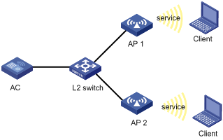
Configuration procedure
1. Configure the AC:
# Enable WLAN.
<AC> system-view
[AC] wlan enable
# Create a WLAN ESS interface.
<AC> system-view
[AC] interface WLAN-ESS 1
[AC-WLAN-ESS1] quit
# Create a clear-type WLAN service template, set the SSID of the service template to service, and bind the WLAN-ESS interface to this service template.
[AC] wlan service-template 1 clear
[AC-wlan-st-1] ssid service
[AC-wlan-st-1] bind wlan-ess 1
[AC-wlan-st-1] authentication-method open-system
[AC-wlan-st-1] description hall
[AC-wlan-st-1] service-template enable
[AC-wlan-st-1] quit
# Configure an AP template named ap1.
[AC] wlan ap ap1 model WA3628i-AGN
[AC-wlan-ap-ap1] serial-id 210235A29G007C000020
[AC-wlan-ap-ap1] radio 1 type dot11an
# Bind service template 1 to radio 1.
[AC-wlan-ap-ap1-radio-1] service-template 1
[AC-wlan-ap-ap1-radio-1] radio enable
[AC-wlan-ap-ap1-radio-1] quit
[AC-wlan-ap-ap1] quit
[AC] port-security enable
# Create a WLAN-ESS interface, configure WLAN port security, set the authentication mode to PSK, and the pre-shared key to 12345678.
[AC] interface wlan-ess 10
[AC-WLAN-ESS10] port-security port-mode psk
[AC-WLAN-ESS10] port-security preshared-key pass-phrase 12345678
[AC-WLAN-ESS10] port-security tx-key-type 11key
[AC-WLAN-ESS10] quit
# Create a crypto-type WLAN service template, set the SSID of the service template to service, and bind the WLAN-ESS interface to this service template.
[AC] wlan service-template 10 crypto
[AC-wlan-st-10] ssid service
[AC-wlan-st-10] bind WLAN-ESS 10
[AC-wlan-st-10] security-ie rsn
[AC-wlan-st-10] cipher-suite ccmp
[AC-wlan-st-10] authentication-method open-system
[AC-wlan-st-10] description office
[AC-wlan-st-10] service-template enable
[AC-wlan-st-10] quit
# Configure an AP template named ap2.
[AC] wlan ap ap2 model WA3628i-AGN
[AC-wlan-ap-ap2] serial-id 210235A29G007C000021
# Bind service template 10 to radio 1.
[AC-wlan-ap-ap2] radio 1 type dot11an
[AC-wlan-ap-ap2-radio-1] service-template 10
[AC-wlan-ap-ap2-radio-1] radio enable
2. Verify the configuration:
¡ The clients can associate with the APs and access the WLAN.
¡ You can use the display wlan client command to view the online clients.
Auto-AP configuration example
Network requirements
As shown in Figure 12, enable the auto AP function on the AC to establish connections to APs. The APs obtain their IP addresses from the DHCP server and provide clear-type WLAN access services with the SSID service1.
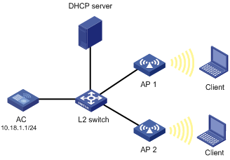
Configuration procedure
1. Configure the AC:
# Create a WLAN ESS interface.
<AC> system-view
[AC] interface WLAN-ESS 1
[AC-WLAN-ESS1] quit
# Define a clear-type WLAN service template, set its SSID to service, and bind the WLAN-ESS interface to this service template.
[AC] wlan service-template 1 clear
[AC-wlan-st-1] ssid service
[AC-wlan-st-1] bind WLAN-ESS 1
[AC-wlan-st-1] authentication-method open-system
[AC-wlan-st-1] service-template enable
[AC-wlan-st-1] quit
# Configure a radio policy.
[AC] wlan radio-policy radpolicy1
[AC-wlan-rp-radpolicy1] beacon-interval 200
[AC-wlan-rp-radpolicy1] dtim 4
[AC-wlan-rp-radpolicy1] rts-threshold 2300
[AC-wlan-rp-radpolicy1] fragment-threshold 2200
[AC-wlan-rp-radpolicy1] short-retry threshold 6
[AC-wlan-rp-radpolicy1] long-retry threshold 5
[AC-wlan-rp-radpolicy1] max-rx-duration 500
[AC-wlan-rp-radpolicy1] quit
# Enable the auto AP function.
[AC] wlan auto-ap enable
# Create an auto-AP template for model WA2610E-AGN.
[AC] wlan ap ap1 model WA2610E-AGN
[AC-wlan-ap-ap1] serial-id auto
# Bind service template 1 to radio 1 and enable the radio.
[AC-wlan-ap-ap1] radio 1 type dot11an
[AC-wlan-ap-ap1-radio-1] service-template 1
[AC-wlan-ap-ap1-radio-1] radio enable
2. Verify the configuration:
¡ You can use the display wlan ap command to view the two APs.
¡ The clients can associate with the APs and access the WLAN.
Auto-AP authentication configuration example
Network requirements
As shown in Figure 13, enable the auto-AP function, and configure auto-AP authentication on the AC to permit AP 1 and deny AP 2. Use the DHCP server to assign IP addresses to authenticated APs. Use the RADIUS server to authenticate unauthenticated APs (AP 3 in this example).
The serial IDs of AP 1, AP 2, and AP 3 are 210235A42QB095000761, 210235A42QB095000762, and 210235A42QB095000763, respectively.
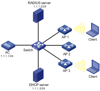
Configuration procedure
1. Configure the AC:
# Create ACL 202.
<AC> system-view
[AC] acl number 202
# Configure ACL rules to permit AP 1 with serial ID 210235A42QB095000761 and deny AP 2 with serial ID 210235A42QB095000762.
[AC-acl-ap-202] rule permit serial-id 210235A42QB095000761
[AC-acl-ap-202] rule deny serial-id 210235A42QB095000762
[AC-acl-ap-202] quit
# Enable the serial-ID authentication method.
[AC] wlan ap-authentication method serial-id
# Use ACL 202 to match auto APs.
[AC] wlan ap-authentication acl 202
# Create a RADIUS scheme rad, and specify the extended RADIUS server type.
[AC] radius scheme rad
[AC-radius-rad] server-type extended
# Set the IP address of the primary authentication server to 1.1.1.2.
[AC-radius-rad] primary authentication 1.1.1.2
# Set the shared key for RADIUS authentication packets to 12345678.
[AC-radius-rad] key authentication 12345678
[AC-radius-rad] user-name-format without-domain
[AC-radius-rad] quit
# Configure AAA domain auto by referencing RADIUS scheme rad.
[AC] domain auto
[AC-isp-auto] authentication wlan-ap radius-scheme rad
[AC-isp-auto] quit
[AC] wlan ap-authentication domain auto
# Enable the auto AP function.
[AC] wlan auto-ap enable
# Enable auto-AP authentication.
[AC] wlan ap-authentication enable
2. Verify the configuration:
¡ AP 1 matches the permit rule, so it can connect to the AC.
¡ AP 2 matches the deny rule, so it cannot connect to the AC.
¡ AP 3 does not match any rule, so it is authenticated by the remote RADIUS server. If it passes the authentication, it can connect to the AC to provide WLAN services.
Configuration example for AC-AP tunnel encryption with IPsec
Network requirements
As shown in Figure 14, the APs obtain their IP addresses from the DHCP server. The data and control packets between AP 1 and AC are transmitted in plain text, use IPsec to encrypt the AC-AP control tunnel between AP 2 and the AC, and use IPsec to encrypt the AC-AP control and data tunnels between AP 3 and the AC.
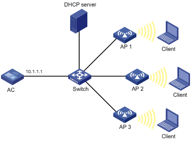
Configuration procedure
Before you configure provision function for AP 2 and AP 3, make sure AP 2 and AP 3 have established connections to the AC and are in Run state.
1. Configure the DHCP server:
Assume the DHCP server assigns IP address ranges 10.1.1.1 to 10.1.1.10 to AP 1, 10.1.1.11 to 10.1.1.20 to AP 2, and 10.1.1.21 to 10.1.1.30 to AP 3. For more information about how to configure the DHCP server, see Layer 3 Configuration Guide.
2. Configure the AC:
# Create AP 2 and enter AP configuration view, configure AP 2 to use IPsec key 12345 to encrypt the control tunnel, and save the configuration to the wlan_ap_cfg.wcfg file of AP 2.
<AC> system-view
[AC] wlan ap ap2 model WA2620E-AGN
[AC-wlan-ap-ap2] provision
[AC-wlan-ap-ap2-prvs] tunnel encryption ipsec pre-shared-key simple 12345
[AC-wlan-ap-ap2-prvs] save wlan ap provision name ap2
[AC-wlan-ap-ap2-prvs] quit
[AC-wlan-ap-ap2] quit
# Create AP 3 and enter AP configuration view, configure AP 3 to use IPsec key abcde to encrypt the control and data tunnels, and save the configuration to the wlan_ap_cfg.wcfg file of AP 3.
[AC] wlan ap ap3 model WA2620E-AGN
[AC-wlan-ap-ap3] provision
[AC-wlan-ap-ap3-prvs] tunnel encryption ipsec pre-shared-key simple abcde
[AC-wlan-ap-ap3-prvs] data-tunnel encryption enable
[AC-wlan-ap-ap3-prvs] save wlan ap provision name ap3
[AC-wlan-ap-ap3-prvs] return
# Reboot AP 2 and AP 3 to apply the configuration.
<AC> reset wlan ap name ap2
<AC> reset wlan ap name ap3
# Configure an IPsec security proposal.
<AC> system-view
[AC] ipsec transform-set tran1
[AC-ipsec-transform-set-tran1] encapsulation-mode tunnel
[AC-ipsec-transform-set-tran1] transform esp
[AC-ipsec-transform-set-tran1] esp encryption-algorithm des
[AC-ipsec-transform-set-tran1] esp authentication-algorithm aes-cbc-128
[AC-ipsec-transform-set-tran1] quit
# Create IKE proposal 1.
[AC] ike proposal 1
[AC-ike-proposal-1]encryption-algorithm aes-cbc 128
[AC-ike-proposal-1] dh group2
[AC-ike-proposal-1] quit
# Set the ISAKMP SA keepalive interval to 20 seconds.
[AC] ike sa keepalive-timer interval 20
# Set the ISAKMP SA keepalive timeout to 60 seconds.
[AC] ike sa keepalive-timer timeout 60
# Enable invalid SPI recovery.
[AC] ipsec invalid-spi-recovery enable
# Configure IKE peer ap2, set the pre-shared key to 12345 (the same as the key on AP 2), and apply IKE proposal 1 to AP 2.
[AC] ike peer ap2
[AC-ike-peer-ap2] remote-address 10.1.1.11 10.1.1.20
[AC-ike-peer-ap2] pre-shared-key 12345
[AC-ike-peer-ap2] proposal 1
[AC-ike-peer-ap2] quit
# Configure IKE peer ap3, set the pre-shared key to abcde (the same as the key on AP 3), and apply IKE proposal 1 to AP 3.
[AC] ike peer ap3
[AC-ike-peer-ap3] remote-address 10.1.1.21 10.1.1.30
[AC-ike-peer-ap3] pre-shared-key abcde
[AC-ike-peer-ap3] proposal 1
[AC-ike-peer-ap3] quit
# Create an IPsec policy template with the name pt and the sequence number 1, and configure the IPsec policy to reference IPsec transform set tran1 and IKE peer ap2.
[AC] ipsec policy-template pt 1
[AC-ipsec-policy-template-pt-1] transform-set tran1
[AC-ipsec-policy-template-pt-1] ike-peer ap2
[AC-ipsec-policy-template-pt-1] quit
# Create an IPsec policy template with the name pt and the sequence number 2, and configure the IPsec policy to reference IPsec transform set tran1 and IKE peer ap3.
[AC] ipsec policy-template pt 2
[AC-ipsec-policy-template-pt-2] transform-set tran1
[AC-ipsec-policy-template-pt-2] ike-peer ap3
[AC-ipsec-policy-template-pt-2] quit
# Reference IPsec policy template pt to create an IPsec policy with the name map and sequence number 1.
[AC] ipsec policy map 1 isakmp template pt
# Apply the IPsec policy to VLAN-interface 1. Tunnel establishment between AP 1 and the AC is not affected by this configuration.
[AC] interface vlan-interface 1
[AC-Vlan-interface-1] ip address 10.1.1.1 24
[AC-Vlan-interface-1] ipsec policy map
Verifying the configuration
Use the display ipsec sa command to display established SAs for IPsec. IKE establishes SAs after an AP sends Join requests to the AC.
Policy-based forwarding configuration example
Network requirements
As shown in Figure 15, apply the policy-based forwarding mode to the service template or the user profile on the AC.
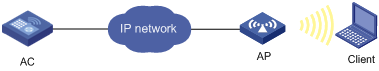
Configuration procedure
1. Edit the configuration file ACL.txt of the AP:
# ACL and the user profile configurations must be included.
acl number 3000
rule 0 permit icmp icmp-type echo
acl ipv6 number 3001
rule 0 permit icmpv6 icmp6-type echo-request
undo user-profile aaa enable
user-profile aaa
wlan forwarding-policy us
user-profile aaa enable
2. Configure the authentication server:
¡ Set the shared key for AC authentication packets to 12345678.
¡ Specify the name and password for the client.
¡ Make sure the name of the user profile is aaa. (Details not shown.)
3. Configure the AC:
# Create forwarding policy st. Configure forwarding rules to forward packets that match ACL 3000 in local forwarding mode and packets that match ACL 3001 in centralized forwarding mode.
<AC> system-view
[AC] wlan forwarding-policy st
[AC-wlan-fp-st] classifier acl 3000 behavior local
[AC-wlan-fp-st] classifier acl ipv6 3001 behavior remote
[AC-wlan-fp-st] quit
# Create forwarding policy us. Configure forwarding rules to forward packets that match ACL 3000 in centralized forwarding mode and packets that match ACL 3001 in local forwarding mode.
[AC] wlan forwarding-policy us
[AC-wlan-fp-us] classifier acl 3000 behavior remote
[AC-wlan-fp-us] classifier acl ipv6 3001 behavior local
[AC-wlan-fp-us] quit
# Enable port security.
[AC] port-security enable
# Enable EAP authentication mode.
[AC] dot1x authentication-method eap
# Create a RADIUS scheme rad, and specify the extended RADIUS server type.
[AC] radius scheme rad
[AC-radius-rad] server-type extended
# Set the IP address of the primary RADIUS authentication server and the primary accounting RADIUS server to 192.168.1.9.
[AC-radius-rad] primary authentication 192.168.1.9
[AC-radius-rad] primary accounting 192.168.1.9
# Set the shared key for RADIUS authentication packets and accounting packets to 12345678.
[AC-radius-rad] key authentication 12345678
[AC-radius-rad] key accounting 12345678
# Configure the AC to remove the domain name from the username sent to the RADIUS server.
[AC-radius-rad] user-name-format without-domain
[AC-radius-rad] quit
# Create authentication domain test, and set the RADIUS authentication, authorization, and accounting schemes to rad.
[AC] domain test
[AC-isp-test] authentication lan-access radius-scheme rad
[AC-isp-test] authorization lan-access radius-scheme rad
[AC-isp-test] accounting lan-access radius-scheme rad
[AC-isp-test] quit
# Configure mandatory authentication domain test for 802.1X clients on interface WLAN-ESS 1.
[AC] interface WLAN-ESS1
[AC-WLAN-ESS1] dot1x mandatory-domain test
# Set the port security mode to userlogin-secure-ext and enable 11key negotiation.
[AC-WLAN-ESS1] port-security port-mode userlogin-secure-ext
[AC-WLAN-ESS1] port-security tx-key-type 11key
# Disable 802.1X multicast trigger and online user handshake functions.
[AC-WLAN-ESS1] undo dot1x handshake
[AC-WLAN-ESS1] undo dot1x multicast-trigger
[AC-WLAN-ESS1] quit
# Create a crypto-type service template, set the SSID of the service template to dot1x, and set the encryption type to TKIP and AES-CCMP.
[AC] wlan service-template 1 crypto
[AC-wlan-st-1] ssid dot1x
[AC-wlan-st-1] bind WLAN-ESS 1
[AC-wlan-st-1] authentication-method open-system
[AC-wlan-st-1] cipher-suite tkip
[AC-wlan-st-1] cipher-suite ccmp
[AC-wlan-st-1] security-ie rsn
# Enable the policy-based forwarding mode and apply it to the service template.
[AC-wlan-st-1] client forwarding-mode policy-based st
# In the centralized forwarding mode, configure packets to be encapsulated in 802.3 form.
[AC-wlan-st-1] client remote-forwarding format dot3
# Enable the service template.
[AC-wlan-st-1] service-template enable
[AC-wlan-st-1] quit
# Specify the model and serial number for AP 1 in the service template.
[AC] wlan ap ap1 model WA2620E-AGN
[AC-wlan-ap-ap1] serial-id 210235A29G007C000020
# Download configuration file ACL.txt to AP 1.
[AC-wlan-ap-ap1] map-configuration ACL.txt
# Bind service template 1 to Radio 2 of AP 1, and enable the service template.
[AC-wlan-ap-ap1] radio 2 type dot11gn
[AC-wlan-ap-ap1-radio-2] service-template 1
[AC-wlan-ap-ap1-radio-2] radio enable
[AC-wlan-ap-ap1-radio-2] quit
[AC-wlan-ap-ap1] quit
# Create and enable the user profile aaa.
[AC] user-profile aaa
[AC-user-profile-aaa] quit
[AC] user-profile aaa enable
Verifying the configuration
Verify that the forwarding policy us takes effect because the forwarding policy in the user profile has a higher priority.
· Use an IPv4 client to ping the IP address that connects the AP to the AC. The ICMP packet matches ACL 3000 and is forwarded by the AC. Before the CAPWAP encapsulation, the AP transfers 802.11 frames to 802.3 frames.
· Use an IPv6 client to ping the IP address that connects the AP to the AC. The ICMPv6 packet matches ACL 3001 and is forwarded by the AP.
802.11n configuration example
Network requirements
As shown in Figure 16, deploy an 802.11n network to provide high-bandwidth access for multimedia applications. The AP provides a plain-text wireless service with SSID 11nservice. 802.11gn is used to inter-work with existing 802.11g networks.
Configuration procedure
1. Configure the AC:
# Create a WLAN-ESS interface.
<AC> system-view
[AC] interface wlan-ess 1
[AC-WLAN-ESS1] quit
# Create a service template of clear type, set the SSID of the service template to 11nservice, and bind the WLAN-ESS interface with the service template.
[AC] wlan service-template 1 clear
[AC-wlan-st-1] ssid 11nservice
[AC-wlan-st-1] bind WLAN-ESS 1
[AC-wlan-st-1] authentication-method open-system
[AC-wlan-st-1] service-template enable
[AC-wlan-st-1] quit
# Configure the AP on the AC, and the AP must support 802.11n.
[AC] wlan ap ap1 model WA2610E-AGN
[AC-wlan-ap-ap1] serial-id 210235A29G007C000020
# Configure the radio of the AP to operate in 802.11g/n mode.
[AC-wlan-ap-ap1] radio 1 type dot11gn
# Bind the service template to radio 1.
[AC-wlan-ap-ap1-radio-1] service-template 1
[AC-wlan-ap-ap1-radio-1] radio enable
2. Verify the configuration:
¡ The clients can associate with the APs and access the WLAN.
¡ You can use the display wlan client verbose command to view the online clients. The command output displays information about 802.11n clients.
802.11ac configuration example
Network requirements
As shown in Figure 17, deploy an 802.11ac network to provide high-bandwidth access for multimedia applications. The AP provides a plain-text wireless service with SSID 11acservice.
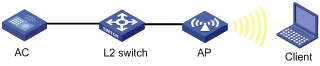
Configuration procedure
1. Configure the AC:
# Create a WLAN-ESS interface.
<AC> system-view
[AC] interface wlan-ess 1
[AC-WLAN-ESS1] quit
# Configure a clear-type service template, set the SSID of the service template to 11acservice, and bind the WLAN-ESS interface to the service template.
[AC] wlan service-template 1 clear
[AC-wlan-st-1] ssid 11acservice
[AC-wlan-st-1] bind WLAN-ESS 1
[AC-wlan-st-1] authentication-method open-system
[AC-wlan-st-1] service-template enable
[AC-wlan-st-1] quit
# Specify the model and serial ID for the AP. The AP you choose must support 802.11ac.
[AC] wlan ap ap1 model WA4620i-ACN
[AC-wlan-ap-ap1] serial-id 210236A35VA10A48231
# Configure the radio of AP 1 to operate in 802.11ac mode.
[AC-wlan-ap-ap1] radio 1 type dot11ac
# Bind the service template to the radio.
[AC-wlan-ap-ap1-radio-1] service-template 1
[AC-wlan-ap-ap1-radio-1] radio enable
2. Verify the configuration:
¡ The client can associate with the AP and then access the WLAN.
¡ You can use the display wlan client verbose command to view the online clients of 802.11ac.
Backup client authentication configuration example
Network requirements
As shown in Figure 18, configure backup client authentication on the AC to achieve the following purposes:
· The AC authenticates clients in the branch.
· When the AC-AP connection fails, the AP authenticates clients and does not log off online clients. A new client can come online by using local authentication.
· When the connection recovers, the AP logs off all clients and the AC re-authenticates clients.
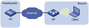
Configuration procedure
1. Add the following commands to the configuration file of the AP:
port-security enable
domain branch.net
authentication lan-access local
authorization lan-access local
accounting lan-access local
local-user 00-14-6c-8a-43-ff
password simple 00-14-6c-8a-43-ff
service-type lan-access
mac-authentication user-name-format mac-address with-hyphen lowercase
Save the configuration file, name it as map.cfg, and put it to the storage media of the AC.
2. Configure the AC:
# Create an access user. Set both the username and password to the MAC address of the client: 00-14-6c-8a-43-ff. Set the service type to lan-access.
<AC> system-view
[AC] local-user 00-14-6c-8a-43-ff
[AC-luser-00-14-6c-8a-43-ff] password simple 00-14-6c-8a-43-ff
[AC-luser-00-14-6c-8a-43-ff] service-type lan-access
[AC-luser-00-14-6c-8a-43-ff] quit
# Configure ISP domain branch.net to use local authentication for LAN access users.
[AC] domain branch.net
[AC-isp-branch.net] authentication lan-access local
[AC-isp-branch.net] quit
# Enable port security.
[AC] port-security enable
# Enable MAC authentication and set branch.net to the authentication domain. The authentication domain must be the same as the domain created in the configuration file of the AP.
[AC] interface wlan-ess 1
[AC-WLAN-ESS1] port-security port-mode mac-authentication
[AC-WLAN-ESS1] mac-authentication domain branch.net
[AC-WLAN-ESS1] quit
# Configure the type of user accounts for MAC authentication users.
[AC] mac-authentication user-name-format mac-address with-hyphen lowercase
# Create a clear-type service template, set the SSID of the service template to backup, and bind the WLAN-ESS interface to the service template.
[AC] wlan service-template 1 clear
[AC-wlan-st-1] ssid backup
[AC-wlan-st-1] bind WLAN-ESS 1
# Specify the backup authentication mode.
[AC-wlan-st-1] authentication-mode backup
[AC-wlan-st-1] service-template enable
[AC-wlan-st-1] quit
# Create an AP template named ap1 and specify the serial ID for the AP.
[AC] wlan ap ap1 model WA2620E-AGN
[AC-wlan-ap-ap1] serial-id 210235A29G007C000020
# Enable the remote AP function.
[AC-wlan-ap-ap1] hybrid-remote-ap enable
# Download configuration file map.cfg to AP 1.
[AC-wlan-ap-ap1] map-configuration map.cfg
# Bind service template 1 to radio 2 of AP 1.
[AC-wlan-ap-ap1] radio 2 type dot11gn
[AC-wlan-ap-ap1-radio-2] service-template 1
[AC-wlan-ap-ap1-radio-2] radio enable
3. Verify the configuration:
¡ Clients associated with the AP can access the network after passing central authentication. In the output of the display wlan client verbose command, the Central field shows that the AC authenticates the clients.
¡ When the connection between AC and AP fails, clients associated with the AP are not logged off. If a new client wants to associate with the AP, local authentication is used.
¡ When the connection between AC and AP recovers, the AP logs off all associated clients. The clients can associate with the AP again after authenticated by the AC. In the output of the display wlan client verbose command, the authentication-mode field displays Central.
Local client authentication configuration example
Network requirements
As shown in Figure 19, configure local client authentication on the AC so the AP performs 802.1X authentication on clients through the RADIUS server.
Deploy the RADIUS server at the AP side so associated 802.1X clients are not logged off when the connection between the branch and headquarters fails.
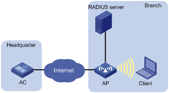
Configuration procedure
1. Add the following commands to the configuration file of the AP:
port-security enable
dot1x authentication-method eap
radius scheme rad
primary authentication 192.168.100.254
primary accounting 192.168.100.254
key authentication simple 123456
key accounting simple 123456
user-name-format without-domain
domain cams
authentication default radius-scheme rad
authorization default radius-scheme rad
accounting default radius-scheme rad
Then, save the configuration file, name it as map.cfg, and put it the storage media of the AC.
2. Configure the AC:
# Specify mandatory 802.1X authentication domain cams on WLAN-ESS1. This domain must the same as the ISP domain created in the configuration file.
<AC> system-view
[AC] interface WLAN-ESS 1
[AC-WLAN-ESS1] dot1x mandatory-domain cams
# Configure the port security mode as userlogin-secure-ext and enable 11key negotiation.
[AC-WLAN-ESS1] port-security port-mode userlogin-secure-ext
[AC-WLAN-ESS1] port-security tx-key-type 11key
# Disable 802.1X multicast trigger and online user handshake functions.
[AC-WLAN-ESS1] undo dot1x multicast-trigger
[AC-WLAN-ESS1] undo dot1x handshake
[AC-WLAN-ESS1] quit
# Configure a crypto-type service template, set the SSID of the service template to local1x, and set the encryption type to AES-CCMP.
[AC] wlan service-template 1 crypto
[AC-wlan-st-1] ssid local1x
[AC-wlan-st-1] bind WLAN-ESS 1
[AC-wlan-st-1] cipher-suite ccmp
[AC-wlan-st-1] security-ie rsn
# Set the local authentication mode.
[AC-wlan-st-1] authentication-mode local
[AC-wlan-st-1] service-template enable
[AC-wlan-st-1] quit
# Create an AP template named ap1 and specify the serial ID for the AP.
[AC] wlan ap ap1 model WA2620E-AGN
[AC-wlan-ap-ap1] serial-id 210235A29G007C000020
# Enable the remote AP function.
[AC-wlan-ap-ap1] hybrid-remote-ap enable
# Download configuration file map.cfg to AP 1.
[AC-wlan-ap-ap1] map-configuration map.cfg
# Bind service template 1 to radio 2 of AP 1.
[AC-wlan-ap-ap1] radio 2 type dot11gn
[AC-wlan-ap-ap1-radio-2] service-template 1
[AC-wlan-ap-ap1-radio-2] radio enable
3. Verify the configuration:
¡ The AP performs 802.1X authentication on clients through the RADIUS server. Execute the display wlan client verbose command on the AC to view detailed client information. The Local field in the output shows that the AP authenticates clients.
¡ The output from the display connection, display dot1x, and display port-security commands on the AC does not contain client information because the AP authenticates clients.
AP upgrade configuration example
Network requirements
As shown in Figure 20, configure the AP version upgrade function to upgrade AP 1 and AP 2. The AC has established an LWAPP tunnel with AP 1, AP 2, and AP 3, respectively.
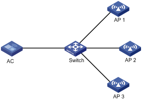
Configuration procedure
Before the following configurations, assume that you have configured AP templates for the three APs on the AC.
# Create AP group update, and add AP 1 and AP 2 to it.
<AC> system-view
[AC] wlan ap-group update
[AC-ap-group-update] ap ap1 ap2
# Enable the AP version update function for the AP group.
[AC-ap-group-update] firmware-update enable
[AC-ap-group-update] quit
[AC] quit
# Enter the template view of AP 3, and disable the version update function.
[AC] wlan ap ap3 model WA2620i-AGN
[AC-wlan-ap-ap3] firmware-update disable
# Download the AP version B109D031 to the AC. (Details not shown.)
# Upgrade the AC's version to B109D031 and reset the AC. AP 1 and AP 2 will try to establish tunnels with the AC of the new version:
· AP 1 and AP 2 compare their versions with that the version of the AC, download the AP version B109D031 from the AC and restart. After reboot, they use version B109D031 to establish LWAPP tunnels with the AC.
· AP 3 does not compare its version with the AC, and uses version B109D001 to establish an LWAPP tunnel with the AC.
Verifying the configuration
Execute the display wlan ap verbose command. The output shows that the versions of AP 1 and AP 2 are B109D031, and the version of AP 3 is B109D001.
AP version rollback configuration example
Network requirements
As shown in Figure 21, the AC has established an LWAPP tunnel with AP 1, AP 2, and AP 3, respectively. Configure AP version rollback so that versions of AP 1 and AP 2 can roll back to B109001.
The AC use the version B109D001, and the three APs are use the version B109D031.
Configuration procedure
Assume that you have completed the following configurations:
· Configure AP templates for the three APs on the AC.
· Enable the AC to accept AP 1, AP 2, and AP 3 with the software version wa2620x Ver.C V100R001B109D031, wa2620x-agnp Ver.C V100R001B109D031, and wa2620i-agn Ver.C V100R001B109D031, respectively.
To configure AP version rollback:
# Create AP group switchback, and add AP 1 and AP 2 to the group.
<AC> system-view
[AC] wlan ap-group switchback
[AC-ap-group-switchback] ap ap1 ap2
[AC-ap-group-switchback] quit
[AC] quit
# Configure AP 1 and AP 2 to use the same software version as the AC.
[AC] undo wlan apdb wa2620x Ver.A V100R001B109D031
[AC] undo wlan apdb wa2620x-agnp Ver.A V100R001B109D031
[AC] quit
# Download the AP version B109D001 to the AC. (Details not shown.)
# Reset all APs in the AP group.
<AC> reset wlan ap ap-group switchback
Verifying the configuration
Execute the display wlan ap verbose command. The output shows that the versions of AP 1 and AP 2 are B109D001, and the version of AP 3 remains as B109D031.
AC and AP version rollback configuration example
Network requirements
As shown in Figure 22, the AC has established an LWAPP tunnel with AP 1, AP 2 and AP 3, respectively. Configure AC and AP version rollback so that versions of the AC, AP 1 and AP 2 can roll back to B109001.
The AC and the three APs use the version B109D031.
Configuration procedure
Before the following configurations, assume that you have configured AP templates for the three APs on the AC.
To configure AC and AP version rollback:
# Download the AC version B109D001 to the AC.
# Download the AP version B109D001 to the AC.
# Enable the AC to accept AP 3 with the software version wa2620i-agn Ver.C V100R001B108D001.
[AC] wlan apdb wa2620i-agn Ver.A V100R001B109D031
# Restart the AC.
Verifying the configuration
Execute the display wlan ap verbose command. The output shows that the versions of AP 1 and AP 2 are B109D001, and the version of AP 3 remains as B109D031.
AP group configuration without roaming
Network requirements
As shown in Figure 23, configure an AP group and apply it in a user profile on the AC so a client can only access the WLAN through AP 1.
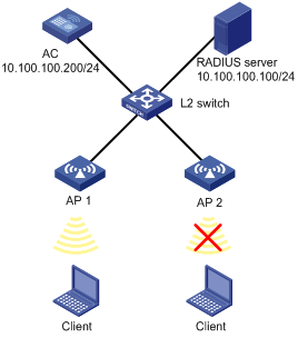
Configuration procedure
1. Configure the AC:
# Enable port security.
<AC> system-view
[AC] port-security enable
# Enable EAP authentication mode.
[AC] dot1x authentication-method eap
# Create a RADIUS scheme.
[AC] radius scheme wlan-user-policy
# Set the RADIUS server and keys for authentication and accounting.
[AC-radius-wlan-user-policy] server-type extended
[AC-radius-wlan-user-policy] primary authentication 10.100.100.100
[AC-radius-wlan-user-policy] primary accounting 10.100.100.100
[AC-radius-wlan-user-policy] key authentication wlan
[AC-radius-wlan-user-policy] key accounting wlan
# Set the IP address of the AC.
[AC-radius-wlan-user-policy] nas-ip 10.100.100.200
[AC-radius-wlan-user-policy] quit
# Configure an ISP domain named universal by referencing the configured RADIUS scheme.
[AC] domain universal
[AC-isp-universal] authentication default radius-scheme wlan-user-policy
[AC-isp-universal] authorization default radius-scheme wlan-user-policy
[AC-isp-universal] accounting default radius-scheme wlan-user-policy
[AC-isp-universal] quit
# Set the default domain to domain universal.
[AC] domain default enable universal
# Configure port security on interface WLAN-ESS 1.
[AC] interface wlan-ess 1
[AC-WLAN-ESS1] port-security port-mode userlogin-secure-ext
[AC-WLAN-ESS1] port-security tx-key-type 11key
[AC-WLAN-ESS1] undo dot1x multicast-trigger
[AC-WLAN-ESS1] undo dot1x handshake
[AC-WLAN-ESS1] quit
# Configure a service template.
[AC] wlan service-template 1 crypto
[AC-wlan-st-1] ssid test
[AC-wlan-st-1] bind wlan-ess 1
[AC-wlan-st-1] authentication-method open-system
[AC-wlan-st-1] cipher-suite ccmp
[AC-wlan-st-1] security-ie rsn
[AC-wlan-st-1] service-template enable
[AC-wlan-st-1] quit
# Create an AP template, select the model wa2100, and set the serial ID of the AP to 210235A29G007C000020.
[AC] wlan ap ap1 model wa2100
[AC-wlan-ap-ap1] serial-id 210235A29G007C000020
# Bind the service template to radio 1 and enable radio 1.
[AC-wlan-ap-ap1] radio 1 type dot11g
[AC-wlan-ap-ap1-radio1] service-template 1
[AC-wlan-ap-ap1-radio1] radio enable
[AC-wlan-ap-ap1-radio1] return
# Add AP 1 to AP group 11, apply the AP group to user profile management and enable the user profile.
<AC> system-view
[AC] wlan ap-group 11
[AC-ap-group11] ap ap1
[AC-ap-group11] quit
[AC] user-profile management
[AC-user-profile-management] wlan permit-ap-group 11
[AC-user-profile-management] quit
[AC] user-profile management enable
2. Configure the RADIUS server:
# Deploy a user profile on the RADIUS server.
Log in to IMC. On the left navigation tree, select Service Management > Service Config. Click Add on the page to enter the following configuration page. Select Deploy User Profile.
Figure 24 Deploying a user profile
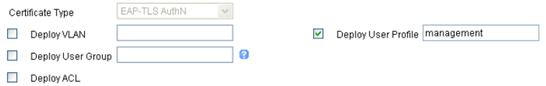
3. Verify the configuration:
The AP group applied in the user profile contains only AP 1, so a client can only access the WLAN through AP 1.
AP group configuration for inter-AC roaming
Network requirements
As shown in Figure 25, AC 1 and AC 2 belong to the same mobility group. Configure an AP group on the ACs so a client can still access the WLAN when it moves between APs.

Configuration procedure
Configuration on the RADIUS server is similar with that in Configure the RADIUS server: and is omitted.
1. Configure AC 1:
# Enable port security.
<AC1> system-view
[AC1] port-security enable
# Enable EAP authentication mode.
[AC1] dot1x authentication-method eap
# Configure port security on interface WLAN-ESS 1.
[AC1] interface wlan-ess 1
[AC1-WLAN-ESS1] port-security port-mode userlogin-secure-ext
[AC1-WLAN-ESS1] port-security tx-key-type 11key
[AC1-WLAN-ESS1] undo dot1x multicast-trigger
[AC1-WLAN-ESS1] undo dot1x handshake
[AC1-WLAN-ESS1] quit
# Define a crypto type WLAN service template, configure the SSID as abc, and bind the WLAN-ESS interface to this service template.
[AC1] wlan service-template 1 crypto
[AC1-wlan-st-1] ssid abc
[AC1-wlan-st-1] bind wlan-ess 1
[AC1-wlan-st-1] authentication-method open-system
[AC1-wlan-st-1] cipher-suite ccmp
[AC1-wlan-st-1] security-ie rsn
[AC1-wlan-st-1] service-template enable
[AC1-wlan-st-1] quit
# Create an AP template named ap1, and set its model to WA3628i-AGN, and serial ID to 210235A045B05B1236548.
[AC1] wlan ap ap1 model WA3628i-AGN
[AC1-wlan-ap-ap1] serial-id 210235A045B05B1236548
[AC1-wlan-ap-ap1] radio 1 type dot11an
# Bind service template 1 to radio 1.
[AC1-wlan-ap-ap1-radio-1] service-template 1
[AC1-wlan-ap-ap1-radio-1] radio enable
[AC1-wlan-ap-ap1-radio-1] quit
[AC1-wlan-ap-ap1] quit
# Configure mobility group abc and enable the mobility group.
[AC1] wlan mobility-group abc
[AC1-wlan-mg-abc] source ip 10.18.1.1
[AC1-wlan-mg-abc] member ip 10.18.1.2
[AC1-wlan-mg-abc] mobility-group enable
[AC1-wlan-mg-abc] return
# Configure AP group 1, add AP 1 and AP 2 in it, apply it to user profile management, and enable the user profile.
<AC1> system-view
[AC1] wlan ap-group 1
[AC1-ap-group1] ap ap1 ap2
[AC1-ap-group1] quit
[AC1] user-profile management
[AC1-user-profile-management] wlan permit-ap-group 1
[AC1-user-profile-management] quit
[AC1] user-profile management enable
2. Configure AC 2:
# Enable port security.
<AC2> system-view
[AC2] port-security enable
# Enable EAP authentication mode.
[AC2] dot1x authentication-method eap
# Configure port security on interface WLAN-ESS 1.
[AC2] interface wlan-ess 1
[AC2-WLAN-ESS1] port-security port-mode userlogin-secure-ext
[AC2-WLAN-ESS1] port-security tx-key-type 11key
[AC2-WLAN-ESS1] undo dot1x multicast-trigger
[AC2-WLAN-ESS1] undo dot1x handshake
[AC2-WLAN-ESS1] quit
# Create a crypto type WLAN service template, set the SSID to abc, and bind the WLAN-ESS interface to this service template.
[AC2] wlan service-template 1 crypto
[AC2-wlan-st-1] ssid abc
[AC2-wlan-st-1] bind wlan-ess 1
[AC2-wlan-st-1] authentication-method open-system
[AC2-wlan-st-1] cipher-suite ccmp
[AC2-wlan-st-1] security-ie rsn
[AC2-wlan-st-1] service-template enable
[AC2-wlan-st-1] quit
# Create an AP template named ap2, and set its model to WA3628i-AGN, and serial ID to 210235A22W0076000103.
[AC2] wlan ap ap2 model WA3628i-AGN
[AC2-wlan-ap-ap2] serial-id 210235A22W0076000103
[AC2-wlan-ap-ap2] radio 1 type dot11an
[AC2-wlan-ap-ap2-radio-1] service-template 1
[AC2-wlan-ap-ap2-radio-1] radio enable
[AC2-wlan-ap-ap2-radio-1] quit
[AC2-wlan-ap-ap2] quit
# Configure mobility group abc and enable the mobility group.
[AC2] wlan mobility-group abc
[AC2-wlan-mg-abc] source ip 10.18.1.2
[AC2-wlan-mg-abc] member ip 10.18.1.1
[AC2-wlan-mg-abc] mobility-group enable
[AC2-wlan-mg-abc] quit
# Configure AP group 1, add AP 1 and AP 2 in it, apply the AP group to user profile management, and enable the user profile.
[AC2] wlan ap-group 1
[AC2-ap-group1] ap ap1 ap2
[AC2-ap-group1] quit
[AC2] user-profile management
[AC2-user-profile-management] wlan permit-ap-group 1
[AC2-user-profile-management] quit
[AC2] user-profile management enable
3. Verify the configuration:
AP 1 and AP 2 are permitted in the AP group and a client can roam between them.
Client IP address monitoring configuration example
Network requirements
As shown in Figure 26, the AC acts as the DHCP server. The AP and the client obtain IP addresses from the DHCP server. Configure the client IP address monitoring function on the AC to monitor the IP address changes of the client.
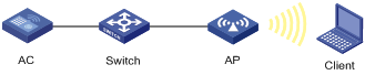
Configuration procedure
1. Configure the DHCP service on the AC:
# Enable the DHCP service.
<AC> system-view
[AC] dhcp enable
[AC] interface vlan 1
[AC-Vlan-interface1] ip address 192.168.0.1 16
[AC-Vlan-interface1] quit
# Create DHCP address pool 1, and specify the subnet for dynamic allocation in the DHCP address pool.
[AC] dhcp server ip-pool 1
[AC-dhcp-pool-1] network 192.168.0.0 16
[AC-dhcp-pool-1] quit
2. Enable client IP address monitoring:
[AC]wlan client learn-ipaddr enable
Verifying the configuration
1. The AC prints a Syslog message when the IP address of the client changes.
When the client comes online, goes offline, fails the authentication, or updates the IP address, the AC prints a Syslog message with the new IP address in it.
2. You can use the display command to view IP addresses of clients offered by the DHCP server.
# Display the client IP address assigned by the DHCP server on the AC.
[AC]display wlan client ip source binding
Total Number of Clients : 1
IP Source Binding Information
------------------------------------------------------------
MAC Address APID/RID Type Binding IP Address
------------------------------------------------------------
001c-f08f-f7f1 20/2 DHCP 192.168.0.6
------------------------------------------------------------