- Table of Contents
-
- 02-WLAN Configuration Guide
- 00-Preface
- 01-WLAN Interface Configuration
- 02-WLAN Access Configuration
- 03-WLAN Security Configuration
- 04-IACTP Tunnel and WLAN Roaming Configuration
- 05-WLAN RRM Configuration
- 06-WLAN IDS Configuration
- 07-WLAN QoS Configuration
- 08-WLAN Mesh Link Configuration
- 09-Advanced WLAN Configuration
- 10-WLAN High Availability Configuration
- 11-WLAN IPS Configuration
- 12-WLAN Optimization Configuration
- Related Documents
-
| Title | Size | Download |
|---|---|---|
| 05-WLAN RRM Configuration | 791.21 KB |
Configuring data transmit rates
Configuring 802.11a/802.11b/802.11g rates
Configuring a channel utilization alarm threshold
Configuring the maximum bandwidth
Configuring 802.11g protection
Configuring 802.11g protection mode
Configuring 802.11n protection
Configuring 802.11n protection mode
Configuring DFS trigger parameters
Configuring automatic mesh DFS
Configuring TPC trigger parameters
Configuring the minimum transmission power
Configuring interference trap thresholds
Displaying and maintaining WLAN RRM
Load balancing configuration task list
Configuring a load balancing mode
Configuring group-based load balancing
Configuring parameters that affect load balancing
Displaying and maintaining load balancing
Enabling band navigation globally
Enabling band navigation for an AP
Configuring band navigation parameters
WLAN RRM configuration examples
Load balancing configuration examples
Configuring session-mode load balancing
Configuring traffic-mode load balancing
Configuring group-based session-mode load balancing
Configuring group-based traffic-mode load balancing
Band navigation configuration example
Configuring WLAN RRM
Overview
Radio signals are susceptible to surrounding interference. The causes of radio signal attenuation in different directions are very complex. Make careful plans before deploying a WLAN network. After WLAN deployment, the running parameters must still be adjusted because the radio environment is always varying due to interference from mobile obstacles, microwave ovens and so on. To adapt to environment changes, radio resources such as working channels and transmit power should be adjusted dynamically. Such adjustments are complex and require experienced personnel to implement regularly, which brings high maintenance costs.
WLAN radio resource management (RRM) is a scalable radio resource management solution. APs collect radio environment information in real time. The AC analyzes the collected information. The AC makes radio resource adjustment configuration according to analysis results. APs implement the configuration made by the AC for radio resource optimization. Therefore, through information collection, information analysis, decision-making, and implementation, WLAN RRM delivers a real-time, intelligent, and integrated radio resource management solution. This enables a WLAN network to quickly adapt to radio environment changes and remain in a healthy state.
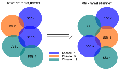
Dynamic frequency selection
A WLAN has limited working channels. Channel overlapping occurs very easily. In addition, other radio sources such as radar and microwave ovens might interfere with the operation of APs. Dynamic frequency selection (DFS) can solve these problems.
With DFS, the AC selects an optimal channel for each AP in real time to avoid co-channel interference and interference from other radio sources.
The following conditions determine DFS:
· Error code rate—Physical layer error code and CRC errors.
· Interference—Influence of 802.11 and non-802.11 wireless signals on wireless services.
· Retransmission—APs retransmit data if they do not receive ACK messages from the AC.
· Radar signal detected on a working channel—The AC immediately notifies the AP to change its working channel.
If any of the first three conditions is met, the AC selects a new channel for the AP. However, the AP does not use the new channel until the channel quality difference between the new and old channels exceeds the tolerance level.
Figure 1 Dynamic channel adjustment
Transmit power control
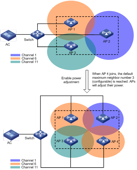
Traditionally, an AP uses the maximum power to cover an area as large as possible. This method, however, affects the operation of surrounding wireless devices. Transmit power control (TPC) is used to select a proper transmission power for each AP to satisfy both coverage and usage requirements.
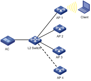
Whether the transmission power of an AP is increased or decreased is determined by these factors: the maximum number of neighbors (detected neighbors that are managed by the same AC), the neighbor AP that performs power detection, and the power adjustment threshold.
As shown in Figure 2, APs 1, 2 and 3 cover an area. When AP 4 joins, the default maximum neighbor number 3 (configurable) is reached. Among all the neighbors AP 2, AP 3, and AP 4 of AP 1, the signal strength of AP 4 is the third, so AP 4 becomes the AP that performs power detection. If AP 4 detects that the power of AP 1 is –75 dBm, which is lower than the default power adjustment threshold –65 dBm (configurable), AP 1 increases its transmission power. If AP 4 detects that the power of AP 1 is –55 dBm, which is higher than the power adjustment threshold –65 dBm, AP 1 decreases its transmission power.
The maximum number of neighbors and the neighbor AP that performs power detection are configured with the dot11a adjacency-factor or dot11bg adjacency-factor command.
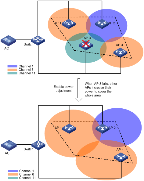
The adjusted transmission power cannot be smaller than the minimum transmission power.
As shown in Figure 3, when AP 3 fails or goes offline, the other APs increase their transmission power to cover the signal blackhole.
Configuration task list
|
Task |
Remarks |
|
Optional |
|
|
Optional |
|
|
Optional |
|
|
Optional |
|
|
Optional |
|
|
Optional |
|
|
Optional |
|
|
Optional |
|
|
Optional |
|
|
Optional |
|
|
Optional |
|
|
Optional |
|
|
Optional |
|
|
Optional |
|
|
Optional |
Configuring data transmit rates
Configuring 802.11a/802.11b/802.11g rates
|
Step |
Command |
Remarks |
|
1. Enter system view. |
system-view |
N/A |
|
2. Enter WLAN RRM view. |
wlan rrm |
N/A |
|
3. Configure rates (in Mbps) for 802.11a. |
dot11a { disabled-rate | mandatory-rate | multicast-rate | supported-rate } rate-value |
Optional. By default: · Disabled rates—None. · Mandatory rates—6, 12, and 24. · Multicast rates—Automatically selected from mandatory rates supported by all clients. · Supported rates—9, 18, 36, 48, and 54. |
|
4. Configure rates for 802.11b. |
dot11b { disabled-rate | mandatory-rate | multicast-rate | supported-rate } rate-value |
Optional. By default: · Disabled rates—None. · Mandatory rates—1 and 2. · Multicast rates—Automatically selected from mandatory rates supported by all clients. · Supported rates—5.5 and 11. |
|
5. Configure rates for 802.11g. |
dot11g { disabled-rate | mandatory-rate | multicast-rate | supported-rate } rate-value |
Optional. By default: · Disabled rates—None. · Mandatory rates—1, 2, 5.5, and 11. · Multicast rates—Automatically selected from mandatory rates supported by all clients. · Supported rates—6, 9, 12, 18, 24, 36, 48, and 54. |
Configuring 802.11n rates
Configuration of mandatory and supported 802.11n rates is achieved by specifying the maximum Modulation and Coding Scheme (MCS) index. The MCS data rate table shows relations between data rates, MCS indexes, and parameters that affect data rates. A sample MCS data rate table (20 MHz) is shown in Table 1, and a sample MCS data rate table (40 MHz) is shown in Table 2. For the whole table, see IEEE 802.11n-2009. Support for MCS indexes depends on the device model.
As shown in the two tables:
· MCS 0 through MCS 7 use one spatial stream, and the data rate corresponding to MCS 7 is the highest.
· MCS 8 through MCS 15 use two spatial streams, and the data rate corresponding to MCS 15 is the highest.
· MCS 16 through MCS 23 use three spatial streams, and the data rate corresponding to MCS 23 is the highest.
Table 1 MCS data rate table (20 MHz)
|
MCS index |
Number of spatial streams |
Modulation |
Data rate (Mbps) |
|
|
800ns GI |
400ns GI |
|||
|
0 |
1 |
BPSK |
6.5 |
7.2 |
|
1 |
1 |
QPSK |
13.0 |
14.4 |
|
2 |
1 |
QPSK |
19.5 |
21.7 |
|
3 |
1 |
16-QAM |
26.0 |
28.9 |
|
4 |
1 |
16-QAM |
39.0 |
43.3 |
|
5 |
1 |
64-QAM |
52.0 |
57.8 |
|
6 |
1 |
64-QAM |
58.5 |
65.0 |
|
7 |
1 |
64-QAM |
65.0 |
72.2 |
|
8 |
2 |
BPSK |
13.0 |
14.4 |
|
9 |
2 |
QPSK |
26.0 |
28.9 |
|
10 |
2 |
QPSK |
39.0 |
43.3 |
|
11 |
2 |
16-QAM |
52.0 |
57.8 |
|
12 |
2 |
16-QAM |
78.0 |
86.7 |
|
13 |
2 |
64-QAM |
104.0 |
115.6 |
|
14 |
2 |
64-QAM |
117.0 |
130.0 |
|
15 |
2 |
64-QAM |
130.0 |
144.4 |
|
16 |
3 |
BPSK |
19.5 |
21.7 |
|
17 |
3 |
QPSK |
39.0 |
43.3 |
|
18 |
3 |
QPSK |
58.5 |
65.0 |
|
19 |
3 |
16-QAM |
78.0 |
86.7 |
|
20 |
3 |
16-QAM |
117.0 |
130.0 |
|
21 |
3 |
64-QAM |
156.0 |
173.3 |
|
22 |
3 |
64-QAM |
175.5 |
195.0 |
|
23 |
3 |
64-QAM |
195.0 |
216.7 |
Table 2 MCS data rate table (40 MHz)
|
MCS index |
Number of spatial streams |
Modulation |
Data rate (Mbps) |
|
|
800ns GI |
400ns GI |
|||
|
0 |
1 |
BPSK |
13.5 |
15.0 |
|
1 |
1 |
QPSK |
27.0 |
30.0 |
|
2 |
1 |
QPSK |
40.5 |
45.0 |
|
3 |
1 |
16-QAM |
54.0 |
60.0 |
|
4 |
1 |
16-QAM |
81.0 |
90.0 |
|
5 |
1 |
64-QAM |
108.0 |
120.0 |
|
6 |
1 |
64-QAM |
121.5 |
135.0 |
|
7 |
1 |
64-QAM |
135.0 |
150.0 |
|
8 |
2 |
BPSK |
27.0 |
30.0 |
|
9 |
2 |
QPSK |
54.0 |
60.0 |
|
10 |
2 |
QPSK |
81.0 |
90.0 |
|
11 |
2 |
16-QAM |
108.0 |
120.0 |
|
12 |
2 |
16-QAM |
162.0 |
180.0 |
|
13 |
2 |
64-QAM |
216.0 |
240.0 |
|
14 |
2 |
64-QAM |
243.0 |
270.0 |
|
15 |
2 |
64-QAM |
270.0 |
300.0 |
|
16 |
3 |
BPSK |
40.5 |
45 |
|
17 |
3 |
QPSK |
81.0 |
90.0 |
|
18 |
3 |
QPSK |
121.5 |
135.0 |
|
19 |
3 |
16-QAM |
162.0 |
180.0 |
|
20 |
3 |
16-QAM |
243.0 |
270.0 |
|
21 |
3 |
64-QAM |
324.0 |
360.0 |
|
22 |
3 |
64-QAM |
364.5 |
405.0 |
|
23 |
3 |
64-QAM |
405.0 |
450.0 |
802.11 rates fall into three types: mandatory rates, supported rates, and multicast rates.
· Mandatory rates—The AP must support mandatory rates. Clients can only associate with the 802.11n AP when they support the mandatory rates.
· Supported rates—These are higher rates supported by the AP besides the mandatory rates. Supported rates allow some clients that support both mandatory and supported rates to choose higher rates when communicating with the AP.
· Multicast rates—These are rates that are supported by the AP besides the mandatory rates. Multicast rates allow clients to send multicast packets at the multicast rates.
When you specify the maximum MCS index, you actually specify a range. For example, if you specify the maximum MCS index as 5 for mandatory rates, rates corresponding to MCS indexes 0 through 5 are configured as 802.11n mandatory rates.
To configure 802.11n rates:
|
Step |
Command |
Remarks |
|
1. Enter system view. |
system-view |
N/A |
|
2. Enter RRM view. |
wlan rrm |
N/A |
|
3. Specify the maximum MCS index for 802.11n mandatory rates. |
dot11n mandatory maximum-mcs index |
Optional. By default, no maximum MCS index is specified for 802.11n mandatory rates. If you configure the client dot11n-only command, you must specify the maximum MCS index. |
|
4. Specify the maximum MCS index for 802.11n supported rates. |
dot11n support maximum-mcs index |
Optional. By default, the maximum MCS index for 802.11n supported rates is 76. |
|
5. Specify the MCS index for 802.11n multicast rates. |
dot11n multicast-rate index |
Optional. By default, the MCS index for 802.11n multicast rates is not specified. Configure the same MCS index settings for APs using 802.11n radios in a mesh network. |
Configuring 802.11ac rates
Configuration of 802.11ac radio rate is achieved by specifying the number of spatial streams (NSS). 802.11ac uses very high throughput modulation and coding scheme (VHT-MCS) to indicate WLAN data rates. A VHT-MCS data rate table shows relations between data rates, VHT-MCSindexes, and parameters that affect data rates. In 802.11ac, the physical transmission rate upon specific parameters corresponding to the VHT-MCS index is determined by the VHT-MCS rate table and NSS. Sample VHT-MCS data rate tables for 20 MHz, 40 MHz, and 80 MHz are shown in Table 3, Table 4, and Table 5, respectively. For the entire table, see IEEE Draft P802.11ac_D5.0.
The value range for NSS is 1 to 8, and the value range for VHT-MCS index in each NSS is 0 to 9.
|
|
NOTE: Support for NSS depends on the device model. |
Table 3 VHT-MCS rate table (20 MHz Nss =1)
|
VHT-MCS Index |
Modulation |
Data Rate (Mbps) |
|
|
800ns GI |
400ns GI |
||
|
0 |
BPSK |
6.5 |
7.2 |
|
1 |
QPSK |
13.0 |
14.4 |
|
2 |
QPSK |
19.5 |
21.7 |
|
3 |
16-QAM |
26.0 |
28.9 |
|
4 |
16-QAM |
39.0 |
43.3 |
|
5 |
64-QAM |
52.0 |
57.8 |
|
6 |
64-QAM |
58.5 |
65.0 |
|
7 |
64-QAM |
65.0 |
72.2 |
|
8 |
256-QAM |
78.0 |
86.7 |
|
9 |
not valid |
||
Table 4 VHT-MCS rate table (40 MHz Nss =1)
|
MCS Index |
Modulation |
Data Rate (Mbps) |
|
|
800ns GI |
400ns GI |
||
|
0 |
BPSK |
13.5 |
15.0 |
|
1 |
QPSK |
27.0 |
30.0 |
|
2 |
QPSK |
40.5 |
45.0 |
|
3 |
16-QAM |
54.0 |
60.0 |
|
4 |
16-QAM |
81.0 |
90.0 |
|
5 |
64-QAM |
108.0 |
120.0 |
|
6 |
64-QAM |
121.5 |
135.0 |
|
7 |
64-QAM |
135.0 |
150.0 |
|
8 |
256-QAM |
162.0 |
180.0 |
|
9 |
256-QAM |
180.0 |
200.0 |
Table 5 VHT-MCS rate table (80 MHz Nss =1)
|
MCS Index |
Modulation |
Data Rate (Mbps) |
|
|
800ns GI |
400ns GI |
||
|
0 |
BPSK |
29.3 |
32.5 |
|
1 |
QPSK |
58.5 |
65.0 |
|
2 |
QPSK |
87.8 |
97.5 |
|
3 |
16-QAM |
117.0 |
130.0 |
|
4 |
16-QAM |
175.5 |
195.0 |
|
5 |
64-QAM |
234.0 |
260.0 |
|
6 |
64-QAM |
263.3 |
292.5 |
|
7 |
64-QAM |
292.5 |
325.0 |
|
8 |
256-QAM |
351.0 |
390.0 |
|
9 |
256-QAM |
390.0 |
433.3 |
NSS is divided into the following types:
· Mandatory NSS—Mandatory rates must be supported by the AP and the clients that want to associate with the 802.11ac AP.
· Supported NSS—Supported NSS allow some clients that support both mandatory and supported NSS to choose higher rates when communicating with the AP.
· Multicast NSS—Multicast NSS allow some devices that support both mandatory and multicast NSS to transmit multicast data with configured multicast NSS.
The NSS value refers to a value range, starting from 0 and ending with the configured value. For example, if you enter 5, the value range for NSS is 0 to 5.
When configuring multicast rate for 802.11ac radio, you need to specify the multicast NSS and multicast VHT-MCS.
To configure 802.11ac rates:
|
Step |
Command |
Remarks |
|
1. Enter system view. |
system-view |
N/A |
|
2. Enter RRM view. |
wlan rrm |
N/A |
|
3. Specify the maximum NSS for 802.11ac mandatory rates. |
dot11ac mandatory maximum-nss number |
Optional. By default, no maximum mandatory NSS specified. If you configure the client { dot11n-only | dot11ac-only } command, you must specify the maximum mandatory NSS. |
|
4. Specify the maximum NSS for 802.11ac supported rates. |
dot11ac support maximum- nss number |
Optional. By default, the maximum supported NSS is 8. |
|
5. Specify the 802.11ac multicast rate. |
dot11ac multicast-rate nss number vht-mcs index |
Optional. By default, no 802.11ac multicast rate is specified. |
Configuring channel exclusion
To avoid selecting improper channels, you can exclude specific channels from automatic channel selection. The excluded channels will not be available for initial automatic channel selection, DFS, and mesh DFS. This feature does not affect rogue detection and WIDS.
Follow these guidelines when you configure channel exclusion:
· The channel exclusion list is not restricted by the country code. You can add channels not supported by the country code to the list, and changing the country code does not change the channel list. The device will select an available channel from the channels supported by the country code and not in the channel exclusion list. When you configure this feature, do not add all channels supported by the country code to the channel exclusion list.
· If you use the dot11a/dot11bg exclude-channel command to add an automatically selected channel into the channel exclusion list, the AC disables the radio, enables the radio, and then selects an available channel from the channels supported by the country code and not in the channel exclusion list.
· For 40 MHz 802.11n radios and 80 MHz or 40 MHz 802.11ac radios, if you add an automatically selected primary channel to the channel exclusion list, the AC will select another available primary channel. If you add a secondary channel into the channel exclusion list in this case, the AC will select another secondary channel. If the AC cannot find an available primary or secondary channel, no channels will be available for the WLAN access and mesh services.
To configure channel exclusion:
|
Step |
Command |
Remarks |
|
1. Enter system view. |
system-view |
N/A |
|
2. Enter WLAN RRM view. |
wlan rrm |
N/A |
|
3. Configure channel exclusion. |
· dot11a exclude-channel channel-list · dot11bg exclude-channel channel-list |
By default, no channel exists in the channel exclusion list. |
Configuring a channel utilization alarm threshold
Perform this task to configure a channel utilization alarm threshold. When the channel utilization reaches the specified threshold, the AC prints logs.
To configure a channel utilization alarm threshold:
|
Step |
Command |
Remarks |
|
1. Enter system view. |
system-view |
N/A |
|
2. Enter RRM view. |
wlan rrm |
N/A |
|
3. Configure a channel utilization alarm threshold. |
channel-utilization threshold threshold |
Optional. By default, the channel utilization alarm threshold is 90%. |
Configuring the maximum bandwidth
The configured maximum bandwidth is used by the load balancing mandatory bandwidth and intelligent bandwidth assurance function. For more information about intelligent bandwidth assurance, see "Configuring WLAN QoS." To apply the configured maximum bandwidth on a radio, you must disable and then enable it.
To configure the maximum bandwidth:
|
Step |
Command |
Remarks |
|
1. Enter system view. |
system-view |
N/A |
|
2. Enter WLAN RRM view. |
wlan rrm |
N/A |
|
3. Configure the maximum bandwidth. |
· 802.11a: · 802.11b: · 802.11g: · 802.11n: |
By default: · The maximum bandwidth for 802.11a is 30000 kbps. · The maximum bandwidth for 802.11b is 7000 kbps. · The maximum bandwidth for 802.11g is 30000 kbps. · The maximum bandwidth for 802.11n is 250000 kbps. Configure the maximum bandwidth close to and smaller than the upper limit of the actual traffic. |
Configuring 802.11g protection
Enabling 802.11g protection
When both 802.11b and 802.11g clients access a WLAN network, their access rates are degraded because they adopt different modulation modes. To enable them to operate correctly, enable 802.11g protection for an 802.11g AP to send RTS/CTS or CTS-to-self packets (the destination of the CTS packets is the device that sends them) so 802.11b devices defer access to the medium.
802.11g protection applies to the following scenarios:
· An 802.11b client associates with the 802.11g/802.11gn AP. In this case, 802.11g protection is always enabled without manual intervention.
· The 802.11g/802.11gn AP detects an overlapping 802.11b BSS or some 802.11b packets that are not destined to it. To enable 802.11g protection, issue the dot11g protection enable command.
To enable 802.11g protection:
|
Step |
Command |
Remarks |
|
1. Enter system view. |
system-view |
N/A |
|
2. Enter WLAN RRM view. |
wlan rrm |
N/A |
|
3. Enable 802.11g protection. |
dot11g protection enable |
Optional. By default, 802.11g protection is disabled. Enabling 802.11g protection reduces network performance. |
Configuring 802.11g protection mode
802.11g protection modes include RTS/CTS and CTS-to-self:
· RTS/CTS—An AP sends an RTS packet before sending data to a client. After receiving the RTS packet, all devices within the coverage of the AP do not send data within the specified time. Upon receiving the RTS packet, the client sends a CTS packet. This makes sure all devices within the coverage of the client do not send data within the specified time.
· CTS-to-Self—An AP uses its IP address to send a CTS packet before it sends data to a client. This ensures that all devices within the coverage of the AP do not send data within the specified time.
To configure the 802.11g protection mode:
|
Step |
Command |
Remarks |
|
1. Enter system view. |
system-view |
N/A |
|
2. Enter WLAN RRM view. |
wlan rrm |
N/A |
|
3. Configure the 802.11g protection mode. |
dot11g protection-mode { cts-to-self | rts-cts } |
Optional. By default, the 802.11g protection mode is CTS-to-Self. |
Configuring 802.11n protection
Enabling 802.11n protection
The 802.11n protection is similar to 802.11g protection. When both 802.11n and non 802.11n devices exist in a WLAN network, enable RTS/CTS or CTS-to-self on 802.11n devices to reduce or avoid collisions on the shared medium.
802.11n protection defines the following different scenarios:
· no protection—The clients associated with the AP and the surrounding wireless devices are operating in 802.11n mode, and all associated clients use the same bandwidth mode, either 40 MHz or 20 MHz.
· Non-member—The clients associated with the AP are operating in 802.11n mode, but non-802.11n wireless devices exist.
· 20 MHz—The bandwidth mode of the AP is 40 MHz, the clients associated with the AP and the surrounding wireless devices are operating in 802.11n mode, and at least one 802.11n client operating in 20 MHz mode is associated with the AP.
· Non-HT mix—Other scenarios.
Follow these guidelines to configure 802.11n protection:
· In a no protection or 20 MHz scenario where all associated clients support greenfield format, no 802.11n protection is needed, because all wireless devices can process all packets.
· In a no protection or 20 MHz scenario where not all associated clients support greenfield format, enable 802.11n protection on the wireless devices that use the HT_GF format to transmit frames.
· In a non-member or non-HT mix scenario where 802.11g or 802.11a wireless devices exist, enable 802.11n protection on the wireless devices that use the HT_GF format to transmit frames and do not enable 802.11n on the wireless devices that use the HT_MF format to transmit frames.
To enable 802.11n protection:
|
Step |
Command |
Remarks |
|
1. Enter system view. |
system-view |
N/A |
|
2. Enter WLAN RRM view. |
wlan rrm |
N/A |
|
3. Enable 802.11n protection. |
dot11n protection enable |
Optional. By default, 802.11n protection is disabled. Enabling 802.11n protection reduces network performance. |
Configuring 802.11n protection mode
802.11n protection modes include RTS/CTS and CTS-to-self:
· RTS/CTS—An AP sends an RTS packet before sending data to a client. After receiving the RTS packet, all devices within the coverage of the AP do not send data within the specified time. Upon receiving the RTS packet, the client sends a CTS packet. This makes sure all devices within the coverage of the client do not send data within the specified time.
· CTS-to-Self—An AP uses its IP address to send a CTS packet before it sends data to a client. This ensures that all devices within the coverage of the AP do not send data within the specified time.
To configure the 802.11n protection mode:
|
Step |
Command |
Remarks |
|
1. Enter system view. |
system-view |
N/A |
|
2. Enter WLAN RRM view. |
wlan rrm |
N/A |
|
3. Configure the 802.11n protection mode. |
dot11n protection-mode { cts-to-self | rts-cts } |
Optional. By default, the 802.11n protection mode is CTS-to-Self. |
Configuring DFS
Follow these guidelines when you configure DFS:
· Before you configure DFS, make sure the AC uses the auto mode (configured by using the channel auto command); otherwise DFS does not work.
· Before you enable DFS, make sure the channel is not locked. If you configure the channel lock command first, and then enable DFS, DFS does not work because the channel is locked. If you enable DFS, and then configure the channel lock command, the last selected channel is locked. For more information about the channel and channel lock commands, see WLAN Command Reference.
· In an AC backup application, the DFS result cannot be synchronized between the primary and backup ACs.
· The commands in this section take effect only on wireless access channels.
Configuring auto-DFS
With auto DFS enabled, an AC performs DFS when the working channel of an AP meets a trigger condition and informs the adjusted channel to the AP after a calibration interval. After that, the AC automatically makes DFS decisions at the calibration interval.
To configure auto DFS:
|
Step |
Command |
Remarks |
|
1. Enter system view. |
system-view |
N/A |
|
2. Enter WLAN RRM view. |
wlan rrm |
N/A |
|
3. Enable auto DFS. |
· dot11a calibrate-channel self-decisive · dot11bg calibrate-channel self-decisive |
By default, auto DFS is disabled. |
|
4. Specify the calibration interval. |
· dot11a calibration-interval minutes · dot11bg calibration-interval minutes |
By default, the calibration interval is 8 minutes. |
Executing one-time DFS
This feature enables the AC to perform DFS when the working channel of the AP meets a trigger condition, and informs the adjusted channel to the AP after a calibration interval. If you want the AC to perform DFS for the AP, you must perform this task again.
To execute one-time DFS:
|
Step |
Command |
Remarks |
|
1. Enter system view. |
system-view |
N/A |
|
2. Enter WLAN RRM view. |
wlan rrm |
N/A |
|
3. Enable channel monitoring. |
· dot11a calibrate-channel · dot11bg calibrate-channel |
Optional. By default, channel monitoring is disabled. |
|
4. Execute one-time DFS. |
· dot11a calibrate-channel pronto ap { all | name apname radio radionum } · dot11bg calibrate-channel pronto ap { all | name apname radio radionum } |
Optional. By default, one-time DFS is not executed. |
|
5. Specify the calibration interval. |
· dot11a calibration-interval minutes · dot11bg calibration-interval minutes |
Optional. By default, the calibration interval is 8 minutes. |
Configuring DFS trigger parameters
The CRC error threshold, interference threshold, and tolerance level determine DFS.
A new channel is selected when either the CRC error threshold or interference threshold is exceeded on the current channel. However, the new channel is not applied until the quality of the current channel is worse than that of the new channel by the tolerance threshold.
To set DFS trigger parameters:
|
Step |
Command |
Remarks |
|
1. Enter system view. |
system-view |
N/A |
|
2. Enter WLAN RRM view. |
wlan rrm |
N/A |
|
3. Configure the CRC error threshold. |
· dot11a crc-error-threshold percent · dot11bg crc-error-threshold percent |
Optional. The default is 20. |
|
4. Configure the interference threshold. |
· dot11a interference-threshold percent · dot11bg interference-threshold percent |
Optional. The default is 50. |
|
5. Configure the tolerance level. |
· dot11a tolerance-level percentage · dot11bg tolerance-level percentage |
Optional. The default is 20 percent. |
Configuring mesh DFS
Before configuring mesh DFS, make sure the AC uses the auto mode (configured by using the channel auto command); otherwise DFS does not work.
In an AC backup application, the mesh DFS result cannot be synchronized between the primary and backup ACs.
The commands in this section take effect only on mesh channels.
Configuring automatic mesh DFS
With mesh auto DFS enabled, an AC performs DFS when the working channel of an AP meets a trigger condition and informs the adjusted channel to the AP after a calibration interval. After that, the AC automatically makes DFS decisions at the calibration interval.
To configure mesh auto DFS:
|
Step |
Command |
Remarks |
|
1. Enter system view. |
system-view |
N/A |
|
2. Enter WLAN RRM view. |
wlan rrm |
N/A |
|
3. Enable mesh auto DFS. |
mesh calibrate-channel self-decisive |
By default, auto DFS is disabled. |
|
4. Specify the calibration interval. |
· dot11a calibration-interval minutes · dot11bg calibration-interval minutes |
By default, the calibration interval is 8 minutes. |
Configuring one-time mesh DFS
With one-time mesh DFS configured for an AP, the AC performs DFS when the working channel of the AP meets a trigger condition, and informs the adjusted channel to the AP after a calibration interval. If you want the AC to perform DFS for the AP, you must make this configuration again.
To configure one-time mesh DFS:
|
Step |
Command |
Remarks |
|
1. Enter system view. |
system-view |
N/A |
|
2. Enter WLAN RRM view. |
wlan rrm |
N/A |
|
3. Enable dynamic mesh channel selection. |
mesh calibrate-channel |
By default, dynamic mesh channel selection is disabled. |
|
4. Configure one-time mesh DFS. |
mesh calibrate-channel pronto mesh-profile { all | mesh-profile-number } |
By default, one-time mesh DFS is not configured. |
|
5. Specify the calibration interval. |
· dot11a calibration-interval minutes · dot11bg calibration-interval minutes |
By default, the calibration interval is 8 minutes. |
Executing channel persistence
This feature enables the device to execute channel persistence on all radios on the AP. After the AC reboots, the AP continues to use the persistent channel.
Channel persistence is applicable to radios used for wireless access, not to auto APs or APs operating in monitor mode.
To execute channel persistence:
|
Step |
Command |
|
1. Enter system view. |
system-view |
|
2. Enter WLAN RRM view. |
wlan rrm |
|
3. Execute channel persistence on all radios. |
dot11a calibrate-channel persistent |
|
dot11bg calibrate-channel persistent |
Configuring TPC
Before enabling TPC, make sure the power is not locked with the power lock command. Otherwise, TPC does not work. If you enable TPC, and then configure the power lock command, the last selected power is locked. For more information about the power lock command, see WLAN Command Reference.
In an AC backup application, the TPC result cannot be synchronized between the primary and backup ACs.
Configuring auto-TPC
With auto TPC enabled, the AC performs TPC for an AP upon certain interference and informs the adjusted power to the AP after a calibration interval. After that, the AC makes TPC decisions at the calibration interval automatically.
To configure auto TPC:
|
Step |
Command |
Remarks |
|
1. Enter system view. |
system-view |
N/A |
|
2. Enter WLAN RRM view. |
wlan rrm |
N/A |
|
3. Enable auto TPC for the band. |
· dot11a calibrate-power self-decisive · dot11bg calibrate-power self-decisive |
Optional. By default, auto TPC for the band is disabled. |
|
4. Specify the calibration interval. |
· dot11a calibration-interval minutes · dot11bg calibration-interval minutes |
Optional. By default, the power calibration interval is 8 minutes. |
Executing one-time TPC
This feature enables the AC to perform TPC for the AP upon certain interference, and informs the adjusted power to the AP after a calibration interval. After that, if you want the AC to perform TPC for the AP, you have to perform this task again.
To execute one-time TPC:
|
Step |
Command |
Remarks |
|
1. Enter system view. |
system-view |
N/A |
|
2. Enter WLAN RRM view. |
wlan rrm |
N/A |
|
3. Enable TPC. |
· dot11a calibrate-power · dot11bg calibrate-power |
Optional. By default, TPC is disabled. |
|
4. Execute one-time TPC. |
· dot11a calibrate-power pronto ap { all | name apname radio radionum } · dot11bg calibrate-power pronto ap { all | name apname radio radionum } |
Optional. By default, one-time TPC for the band is not executed. |
|
5. Specify the calibration interval. |
· dot11a calibration-interval minutes · dot11bg calibration-interval minutes |
By default, the power calibration interval is 8 minutes. |
Configuring TPC trigger parameters
|
Step |
Command |
Remarks |
|
1. Enter system view. |
system-view |
N/A |
|
2. Enter WLAN RRM view. |
wlan rrm |
N/A |
|
3. Configure the maximum number of neighbors and specify the neighbor AP that performs power detection. |
· dot11a adjacency-factor neighbor · dot11bg adjacency-factor neighbor |
Optional. By default, the maximum number of neighbors is 3, and the neighbor AP that performs power detection is the AP whose signal strength is the third among all neighbors. |
|
4. Configure the power adjustment threshold. |
· dot11a calibrate-power threshold value · dot11bg calibrate-power threshold value |
Optional. By default, the power adjustment threshold is 80. |
Configuring the minimum transmission power
The transmission power adjusted by auto-TPC or one-time TPC for an AP cannot be lower than the minimum transmission power set by the dot11a/dot11bg calibrate-power min command to avoid a situation where the AP's signals cannot be detected.
To configure the minimum transmission power level:
|
Step |
Command |
Remarks |
|
1. Enter system view. |
system-view |
N/A |
|
2. Enter WLAN RRM view. |
wlan rrm |
N/A |
|
3. Configure the minimum transmission power. |
· dot11a calibrate-power min tx-power · dot11bg calibrate-power min tx-power |
Optional. By default, the minimum transmission power is 1 dBm. |
Executing power persistence
This feature enables the device to execute power persistence on all radios on the AP. After the AC reboots, the AP continues to use the persistent power.
Power persistence is applicable to radios used for wireless access, not to auto APs or APs operating in monitor mode.
To execute power persistence:
|
Step |
Command |
|
1. Enter system view. |
system-view |
|
2. Enter WLAN RRM view. |
wlan rrm |
|
3. Execute power persistence on all radios. |
· Execute power persistence on all
802.11a radios: · Execute power persistence on all
802.11bg radios: |
Configuring a radio group
With DFS or TPC configured for a radio, the AC calculates the channel quality or power of the radio at the calibration interval. When the result meets a trigger condition, the AC selects a new channel or power for the radio. In an environment where interference is serious, frequent channel or power adjustments might affect user access to the WLAN network. In this case, you can configure a radio group to keep the channel or power of radios in the group unchanged within the specified holddown time. The channel and power of radios not in the radio group are adjusted correctly.
When the holddown time expires, the AC calculates the channel or power again. If the result meets a trigger condition, the channel or power is changed, and the new channel or power remains unchanged within the specified holddown time.
To configure a radio group:
|
Step |
Command |
Remarks |
|
1. Enter system view. |
system-view |
N/A |
|
2. Create a radio group and enter radio group view. |
wlan rrm-calibration-group group-id |
By default, no radio group exists. |
|
3. Configure a description for the radio group. |
description text |
Optional. By default, no description is configured for the radio group. |
|
4. Add a radio of an AP to the radio group. |
ap ap-name radio radio-number |
By default, no radio exists in the radio group. · A member of a radio group is a radio. · One radio can belong to only one radio group. |
|
5. Configure the holddown time for DFS. |
channel holddown-time minutes |
Optional. The default is 720 minutes. If the AC detects any radar signals on the channel within the specified holddown time, the AC immediately selects a new channel and resets the holddown timer. |
|
6. Configure the holddown time for TPC. |
power holddown-time minutes |
Optional. The default is 60 minutes. |
Configuring scan parameters
The scan channel, scan type, and scan report-interval commands apply to rogue device detection, WIDS, and WIPS.
The autochannel-set avoid-dot11h command applies to channel adjustment.
To configure scan parameters:
|
Step |
Command |
Remarks |
|
1. Enter system view. |
system-view |
N/A |
|
2. Enter WLAN RRM view. |
wlan rrm |
N/A |
|
3. Set the scan mode. |
scan channel { auto | all } |
Optional. By default, the scan mode is auto. |
|
4. Set the scan type. |
scan type { active | passive } |
Optional. By default, the scan type is passive. |
|
5. Set the scan report interval. |
scan report-interval seconds |
Optional. By default, the scan report interval is 10 seconds. |
|
6. Configure only non-dot11h channels to be scanned. |
autochannel-set avoid-dot11h |
Optional. By default, all channels supported by the country code are scanned. |
Configuring power constraint
|
Step |
Command |
Remarks |
|
1. Enter system view. |
system-view |
N/A |
|
2. Enter WLAN RRM view. |
wlan rrm |
N/A |
|
3. Enable spectrum management for 802.11a radios. |
spectrum-management enable |
By default, spectrum management is disabled. |
|
4. Configure the power constraint for all 802.11a radios. |
power-constraint power-constraint |
The default power constraint is 0 dBm. |
Configuring interference trap thresholds
Before you configure interference trap thresholds, use the snmp-agent trap enable wlan command to enable WLAN trap function. For more information about the snmp-agent trap enable wlan command, see Network Management and Monitoring Command Reference.
To configure interference trap thresholds:
|
Step |
Command |
Remarks |
|
1. Enter system view. |
system-view |
N/A |
|
2. Enter WLAN RRM view. |
wlan rrm |
N/A |
|
3. Configure the adjacent channel interference trap threshold. |
adjacent-channel interference trap threshold value |
Optional. By default, the adjacent channel interference trap threshold is 60 dBm. |
|
4. Configure the co-channel interference trap threshold. |
co-channel interference trap threshold value |
Optional. By default, the co-channel interference trap threshold is 60 dBm. |
Displaying and maintaining WLAN RRM
|
Task |
Command |
Remarks |
|
Display WLAN RRM information. |
display wlan rrm [ | { begin | exclude | include } regular-expression ] |
Available in any view. |
|
Display the WLAN RRM status of the APs. |
display wlan ap { all | name ap-name } rrm-status [ | { begin | exclude | include } regular-expression ] |
Available in any view. |
|
Display the channel and power change history for APs. |
display wlan ap { all | name ap-name } rrm-history [ | { begin | exclude | include } regular-expression ] |
Available in any view. |
|
Display WLAN RRM information for the APs. |
display wlan ap { all | name ap-name } [ verbose ] [ | { begin | exclude | include } regular-expression ] |
Available in any view. |
|
Display radio group configuration. |
display wlan rrm-calibration-group { group-id | all } [ | { begin | exclude | include } regular-expression ] |
Available in any view. |
|
Display mesh channel adjustment history. |
display wlan mesh calibrate-channel history [ | { begin | exclude | include } regular-expression ] |
Available in any view. |
Load balancing
Overview
WLAN load balancing dynamically adjusts loads among APs to ensure adequate bandwidth for clients. It is mainly used in high-density WLAN networks.
Requirement of WLAN load-balancing implementation
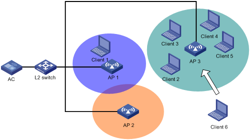
As shown in Figure 4, Client 6 wants to associate with AP 3. AP 3 has reached its maximum load, so it rejects the association request. Client 6 tries to associate with AP 1 or AP 2, but it cannot receive signals from these two APs, so it has to resend an association request to AP 3.
Therefore, to implement load-balancing, the APs must be managed by the same AC, and the clients can find the APs.
Figure 4 Requirement of WLAN load-balancing implementation
Load-balancing modes
The AC supports two load balancing modes, session mode and traffic mode.
· Session mode load-balancing:
Session-mode load balancing is based on the number of clients associated with the AP/radio.
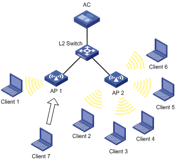
As shown in Figure 5, Client 1 is associated with AP 1, and Client 2 through Client 6 are associated with AP 2. The AC has session-mode load balancing configured: the maximum number of sessions is 5 and the maximum session gap is 4. Then, Client 7 sends an association request to AP 2. The maximum session threshold and session gap have been reached on AP 2, so it rejects the request. Instead, Client 7 associates with AP 1.

· Traffic mode load-balancing:
Traffic snapshot is considered for traffic mode load balancing.
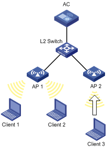
As shown in Figure 6, Client 1 and Client 2 that run 802.11g are associated with AP 1. The AC has traffic-mode load balancing configured: the maximum traffic threshold is 10% and the maximum traffic gap is 20%. Then, Client 3 wants to access the WLAN through AP 1. The maximum traffic threshold and traffic gap (between AP 1 and AP 2) have been reached on AP 1, so it rejects the request. Instead, Client 3 associates with AP 2.
Load-balancing methods
The AC supports AP-based load balancing and group-based load balancing.
AP-based load balancing can be either implemented among APs or among the radios of an AP.
¡ AP-based load balancing
APs can carry out either session-mode or traffic-mode load balancing as configured. An AP starts load balancing when the maximum threshold and gap are reached. It does not accept any association requests unless the load decreases below the maximum threshold or the gap is less than the maximum gap. However, if a client has been denied more than the specified maximum times, the AP considers that the client is unable to associate with any other AP and accepts the association request from the client.
¡ Radio-based load balancing
The radios of an AP that is balanced can carry out either session-mode or traffic-mode load balancing as configured. A radio starts load balancing when the maximum threshold and gap are reached. It rejects any association requests unless the load decreases below the maximum threshold or the gap is less than the maximum gap. However, if a client has been denied more than the specified maximum times, the AP considers that the client is unable to associate with any other AP and accepts the association request from the client.
To balance loads among the radios of different APs, you can add them to the same load balancing group.
The radios in a load balancing group can carry out either session-mode or traffic-mode load balancing as configured. The radios that are not added to any load balancing group do not carry out load balancing. A radio in a load balancing group starts load balancing when the maximum threshold and gap are reached on it. The radio does not accept any association requests unless the load decreases below the maximum threshold or the gap is less than the maximum gap. However, if a client has been denied more than the specified maximum times, the AP considers that the client is unable to associate with any other AP and accepts the association request from the client.
Load balancing configuration task list
If the AC has a load balancing mode configured but has no load balancing group created, it adopts AP-based load balancing by default. As long as a load balancing group is created, the AC adopts Group-based load balancing by default.
|
Task |
Remarks |
|
|
Required Use either approach. |
||
|
Configuring AP-based load balancing |
Required. Use either approach. · AP-based load balancing—After you complete Configuring a load balancing mode, the AC adopts AP-based load balancing by default. · Group-based load balancing—Complete Configuring a load balancing mode first. A load balancing group takes effect only when the load balancing mode is configured. |
|
|
Optional. This configuration takes effect for both AP-based load balancing and radio group load balancing. |
||
|
Optional. |
||
Configuring a load balancing mode
Prerequisites
Before you configure load balancing, make sure of the following:
· The target APs are associated with the same AC.
· The clients can find the APs.
· The fast association function is disabled. By default, the fast association function is disabled. For more information about fast association, see "Configuring WLAN services."
Configuring session mode load balancing
If the AC has a load balancing mode configured but has no load balancing group created, it adopts AP-based load balancing by default.
To configure session mode load balancing:
|
Step |
Command |
Remarks |
|
1. Enter system view. |
system-view |
N/A |
|
2. Enter RRM view. |
wlan rrm |
N/A |
|
3. Configure session mode load balancing. |
load-balance session value [ gap gap-value ] |
By default, no session threshold is set. |
Configuring traffic mode load balancing
If the AC has a load balancing mode configured but has no load balancing group created, it adopts AP-based load balancing by default.
To configure traffic mode load balancing:
|
Step |
Command |
Remarks |
|
1. Enter system view. |
system-view |
N/A |
|
2. Enter RRM view. |
wlan rrm |
N/A |
|
3. Configure traffic mode load balancing. |
load-balance traffic value [ gap gap-value ] |
By default, no traffic threshold is set. |
Configuring group-based load balancing
Prerequisites
Before you configure load balancing, make sure of the following:
· The target APs are associated with the same AC.
· The clients can find the APs.
· The fast association function is disabled. By default, the fast association function is disabled. For more information about fast association, see "Configuring WLAN access."
· A load balancing mode has been configured. For more information, see "Configuring a load balancing mode."
Configuring a load balancing group
|
Step |
Command |
Remarks |
|
1. Enter system view. |
system-view |
N/A |
|
2. Create a load balancing group and enter its view. |
wlan load-balance-group group-id |
By default, no load balancing group exists. |
|
3. Configure a description for the load balancing group. |
description text |
Optional. By default, a load balancing group has no description. |
|
4. Add a radio of an AP to the load balancing group. |
ap ap-name radio radio-number |
By default, no radio exists in a load balancing group. · A member of a load balancing group is a radio. · One radio can belong to only one load balancing group. |
Configuring parameters that affect load balancing
The following parameters affect load balancing calculation:
· Load balancing RSSI threshold—A client may be detected by multiple APs. An AP considers a client whose RSSI is lower than the load balancing RSSI threshold as not detected. If only one AP can detect the client, the AP increases the access probability for the client even if it is overloaded.
· Maximum denial count of client association requests—If the times that a client has been denied reach the specified maximum times, the AP considers that the client is unable to associate with any other AP and accepts the association request from the client.
To configure parameters that affect load balancing:
|
Step |
Command |
Remarks |
|
1. Enter system view. |
system-view |
N/A |
|
2. Enter RRM view. |
wlan rrm |
N/A |
|
3. Configure the load balancing RSSI threshold. |
load-balance rssi-threshold rssi-threshold |
Optional. The default load balancing RSSI threshold is 25. |
|
4. Configure the maximum denial count of client association requests. |
load-balance access-denial access-denial |
Optional. The default value is 10. |
Displaying and maintaining load balancing
|
Task |
Command |
Remarks |
|
Display load balancing configuration. |
display wlan load-balance-group { group-id | all } [ | { begin | exclude | include } regular-expression ] |
Available in any view. |
|
Display basic RRM configurations. |
display wlan rrm [ | { begin | exclude | include } regular-expression ] |
Available in any view. |
|
Display the MAC addresses of all neighbors of the specified AP. |
display wlan load-balance neighbor-list ap ap-name |
Available in any view. |
|
Display the radios that are detected by the specified client and are associated with the same AC. |
display wlan load-balance neighbor-list client mac-address |
Available in any view. |
|
Display clients rejected by load balancing on the specified AP. |
display wlan load-balance reject-client ap ap-name |
Available in any view. |
|
Display the rejection history of the specified client due to load balancing. |
display wlan load-balance reject-client client mac-address |
Available in any view. |
Configuring band navigation
Band navigation enables APs to prefer accepting dual-band (2.4 GHz and 5 GHz) clients on their 5 GHz radio because the 2.4 GHz band is often congested, increasing overall network performance.
When band navigation is enabled, the AP directs clients to its 2.4 GHz or 5 GHz radio by following these principles:
· The AP associates with a 2.4 GHz client on its 2.4 GHz radio after rejecting it several times.
· The AP directs a dual-band client to its 5 GHz radio.
· The AP associates with a 5 GHz- client on its 5 GHz radio.
The AP checks the RSSI of a dual-band client before directing the client to the 5 GHz radio. If the RSSI is lower than the value specified by the band-navigation rssi-threshold command, the AP does not direct the client to the 5 GHz band.
If the number of clients on the 5 GHz radio has reached the upper limit, and the gap between the number of clients on the 5 GHz radio and that on the 2.4 GHz radio has reached the upper limit (the two thresholds are specified by the band-navigation balance session session [ gap gap ] command), the AP denies the client’s association to the 5 GHz radio, and allows new clients to associate with the 2.4 GHz radio. If a client has been denied more than the maximum times on the 5 GHz radio (specified by the band-navigation balance access-denial command), the AP considers that the client is unable to associate with the 2.4 GHz radio, and allows the 5 GHz radio to accept the client.
Configuration guidelines
Follow these guidelines when you configure band navigation:
· When band navigation is enabled, the client association efficiency is affected, so this feature is not recommended in a scenario where most clients use 2.4 GHz.
· Band navigation is not recommended in a delay-sensitive network.
Configuration prerequisites
To enable band navigation to operate correctly, make sure of the following:
· The fast association function is disabled. By default, the fast association function is disabled. For more information about fast association, see "Configuring WLAN access."
· Band navigation is enabled for the AP. By default, band navigation is enabled for the AP.
· The SSID is bound to the 2.4 GHz and 5 GHz radios of the AP.
Enabling band navigation globally
|
Step |
Command |
Remarks |
|
1. Enter system view. |
system-view |
N/A |
|
2. Enter RRM view. |
wlan rrm |
N/A |
|
3. Enable band navigation globally. |
band-navigation enable |
By default, band navigation is disabled globally. Band navigation takes effect for the specified AP only when band navigation is enabled both globally and for the AP. |
Enabling band navigation for an AP
|
Step |
Command |
Remarks |
|
1. Enter system view. |
system-view |
N/A |
|
2. Enter AP template view. |
wlan ap ap-name [ model model-name [ id ap-id ] ] |
N/A |
|
3. Enable band navigation for the AP. |
band-navigation enable |
By default, band navigation is enabled for an AP. Band navigation takes effect for an AP only when band navigation is enabled both globally and for the AP. |
Configuring band navigation parameters
|
Step |
Command |
Remarks |
|
1. Enter system view. |
system-view |
N/A |
|
2. Enter RRM view. |
wlan rrm |
N/A |
|
3. Configure load balancing session threshold and session gap. |
band-navigation balance session session [ gap gap ] |
Optional. By default, band navigation load balancing is disabled. |
|
4. Configure the maximum denial count of association requests sent by a 5 GHz- client. |
band-navigation balance access-denial access-denial |
Optional. By default, the AP does not deny the association requests sent by a 5 GHz- client. |
|
5. Configure the client RSSI threshold. |
band-navigation rssi-threshold rssi-threshold |
Optional. The default RSSI threshold is 15. |
|
6. Configure the client information aging time. |
band-navigation aging-time aging-time |
Optional. The default aging time is 180 seconds. The AP records the client information when a client tries to associate with it. If the AP receives the probe request or association request sent by the client before the aging time expires, the AP refreshes the client information and restarts the aging timer. If not, the AP removes the client information, and does not count the client during band navigation. |
WLAN RRM configuration examples
Configuring auto DFS
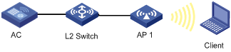
Network requirements
As shown in Figure 7, configure auto DFS on AC so that the AC can perform channel adjustment when the channel of AP 1 is unavailable.
Configuration procedure
# Create a WLAN ESS interface.
<AC> system-view
[AC] interface wlan-ess 1
[AC-WLAN-ESS1] port link-type hybrid
[AC-WLAN-ESS1] quit
# Create service template 1 of clear type, configure its SSID as channel-adjust, and bind WLAN-ESS1 to channel-adjust.
[AC] wlan service-template 1 clear
[AC-wlan-st-1] ssid channel-adjust
[AC-wlan-st-1] bind wlan-ess 1
[AC-wlan-st-1] authentication-method open-system
[AC-wlan-st-1] service-template enable
[AC-wlan-st-1] quit
# Create an AP template named ap1 and its model is WA3628i-AGN, and configure the serial ID of AP 1 as 210235A045B05B1236548.
[AC] wlan ap ap1 model WA3628i-AGN
[AC-wlan-ap-ap1] serial-id 210235A045B05B1236548
[AC-wlan-ap-ap1] radio 2 type dot11gn
# Bind service template 1 to radio 2 of AP 1.
[AC-wlan-ap-ap1-radio-2] service-template 1
[AC-wlan-ap-ap1-radio-2] radio enable
[AC-wlan-ap-ap1-radio-2] quit
[AC-wlan-ap-ap1] quit
# Enable auto DFS.
[AC] wlan rrm
[AC-wlan-rrm] dot11bg calibrate-channel self-decisive
# Configure auto DFS trigger parameters.
[AC-wlan-rrm] dot11bg crc-error-threshold 20
[AC-wlan-rrm] dot11bg interference-threshold 50
[AC-wlan-rrm] dot11bg tolerance-level 20
Verifying the configuration
You can use the display wlan ap { all | name apname } rrm-status command to display the channel information of the AP. When the channel is unavailable, AC will change it, for example, from channel 1 to channel 6 after the calibration interval (configured with the dot11bg calibration-interval command and defaulting to 8 minutes). After the channel change, you can use the display wlan ap { all | name apname } rrm-history command to check the specific reason.
Configuring mesh auto DFS
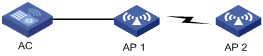
Network requirements
As shown in Figure 8, configure mesh auto DFS on the AC, so that the AC can perform channel adjustment when the mesh channel between AP 1 and AP 2 is unavailable.
Configuration procedure
1. Configure mesh:
For the detailed configuration procedures, see "Configuring WLAN mesh link."
Configure the radio that provides mesh services to automatically select its channel.
2. Configure mesh auto DFS:
# Enable mesh auto DFS.
<AC> system-view
[AC] wlan rrm
[AC-wlan-rrm] mesh calibrate-channel self-decisive
Verifying the configuration
Use the display wlan mesh calibrate-channel history command to view channel adjustment history information. When a trigger condition is met, the AC changes the channel, for example, from channel 149 to channel 153 after the calibration interval.
Configuring auto TPC
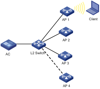
Network requirements
As shown in Figure 9, configure auto TPC and specify the maximum number of neighbors as 3 on the AC so the AC performs auto TPC when AP 4 joins.
Configuration procedure
# Create a WLAN ESS interface.
<AC> system-view
[AC] interface wlan-ess 1
[AC-WLAN-ESS1] port link-type hybrid
[AC-WLAN-ESS1] quit
# Create service template 1 of clear type, configure its SSID as power-adjust, and bind WLAN-ESS1 to power-adjust.
[AC] wlan service-template 1 clear
[AC-wlan-st-1] ssid power-adjust
[AC-wlan-st-1] bind wlan-ess 1
[AC-wlan-st-1] authentication-method open-system
[AC-wlan-st-1] service-template enable
[AC-wlan-st-1] quit
# Create an AP template named ap1 and its model is WA3628i-AGN, and configure the serial ID of AP 1 as 210235A045B05B1236548.
[AC] wlan ap ap1 model WA3628i-AGN
[AC-wlan-ap-ap1] serial-id 210235A045B05B1236548
[AC-wlan-ap-ap1] radio 2 type dot11gn
# Bind service template 1 to radio 2 of AP 1.
[AC-wlan-ap-ap1-radio-2] service-template 1
[AC-wlan-ap-ap1-radio-2] radio enable
[AC-wlan-ap-ap1-radio-2] quit
[AC-wlan-ap-ap1] quit
Configurations of other APs are similar to AP 1, and are not shown.
# Enable auto TPC.
[AC] wlan rrm
[AC-wlan-rrm] dot11bg calibrate-power self-decisive
# Specify the maximum number of neighbors, the power adjustment threshold, and the minimum transmission power.
[AC-wlan-rrm] dot11bg adjacency-factor 3
[AC-wlan-rrm] dot11bg calibrate-power threshold 65
[AC-wlan-rrm] dot11bg calibrate-power min 1
Verifying the configuration
When AP 4 joins, the number of neighbors reaches 3. Assume the signal strength of AP 4 is the third among all neighbors (AP 2, AP 3, and AP 4). AP 4 becomes the neighbor AP that perform power detection. If AP 4 detects that the power of AP 1 is –90 dBm, which is lower than the power adjustment threshold –65 dBm, AP 1 increases its transmission power. If AP 4 detects that the power of AP 1 is –60 dBm, which is higher than the power adjustment threshold –65 dBm, AP 1 decreases its transmission power. You can use the display wlan ap { all | name apname } rrm-status command to check the adjusted power (TxPower).
The adjusted power of AP 1 cannot be lower than the minimum transmission power (1 dBm in this example).
Configuring a radio group
Network requirements
As shown in Figure 10, AP 1 through AP 3 are connected to the AC.
· Configure auto DFS so that the AC can automatically switch the working channel of an AP when the signal quality on that channel is degraded to a certain level.
· Configure auto TPC so that the AC can automatically adjust the power of an AP when the third neighbor of that AP is discovered (or in other words, when AP 4 joins).
· Add radio 2 of AP 1 and radio 2 of AP 2 to a radio group to prevent frequent channel and power adjustments.
Configuration procedure
# Create a WLAN ESS interface.
<AC> system-view
[AC] interface wlan-ess 1
[AC-WLAN-ESS1] port link-type hybrid
[AC-WLAN-ESS1] quit
# Create service template 1 of clear type, configure its SSID as rrm-adjust, and bind WLAN-ESS1 to the service template.
[AC] wlan service-template 1 clear
[AC-wlan-st-1] ssid rrm-adjust
[AC-wlan-st-1] bind wlan-ess 1
[AC-wlan-st-1] authentication-method open-system
[AC-wlan-st-1] service-template enable
[AC-wlan-st-1] quit
# Create an AP template named ap1, and specify its model as WA3628i-AGN, and serial ID as 210235A045B05B1236548.
[AC] wlan ap ap1 model WA3628i-AGN
[AC-wlan-ap-ap1] serial-id 210235A045B05B1236548
[AC-wlan-ap-ap1] radio 2 type dot11gn
# Bind service template 1 to radio 2 of AP 1.
[AC-wlan-ap-ap1-radio-2] service-template 1
[AC-wlan-ap-ap1-radio-2] radio enable
[AC-wlan-ap-ap1-radio-2] quit
[AC-wlan-ap-ap1] quit
# Configurations of other APs are similar to AP1, and are not shown.
# Enable auto DFS and auto TPC.
[AC] wlan rrm
[AC-wlan-rrm] dot11bg calibrate-channel self-decisive
[AC-wlan-rrm] dot11bg calibrate-power self-decisive
# Configure auto DFS trigger parameters (Optional because the parameters has default values).
[AC-wlan-rrm] dot11bg crc-error-threshold 20
[AC-wlan-rrm] dot11bg interference-threshold 50
[AC-wlan-rrm] dot11bg tolerance-level 20
# Configure the auto TPC trigger parameter adjacency factor (Optional because the parameter has a default value by default).
[AC-wlan-rrm] dot11bg adjacency-factor 3
[AC-wlan-rrm] quit
# Create radio group 1.
[AC] wlan rrm-calibration-group 1
# Add radio 2 of AP 1 and radio 2 of AP 2 to the radio group 1.
[AC-wlan-rc-group-1] ap ap1 radio 2
[AC-wlan-rc-group-1] ap ap2 radio 2
# Set the channel holddown time to 20 minutes.
[AC-wlan-rc-group-1] channel holddown-time 20
# Set the power holddown time to 30 minutes.
[AC-wlan-rc-group-1] power holddown-time 30
Verifying the configuration
· The working channel of radio 2 of AP 1 and that of AP 2 do not change within 20 minutes after each automatic channel adjustment.
· The power of radio 2 of AP 1 and that of AP 2 do not change within 30 minutes after each automatic power adjustment.
Load balancing configuration examples
Configuring session-mode load balancing
Network requirements
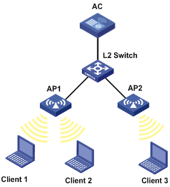
· As shown in Figure 11, all APs operate in 802.11gn mode. Client 1 is associated with AP 1. Client 2 through Client 6 are associated with AP 2.
· Configure session-mode load balancing on the AC. The threshold, or, the maximum number of sessions is 5 and the maximum load gap is 4.
Configuration procedure
# Enable session-mode load balancing, and configure the maximum number of sessions and the maximum load gap as 5 and 4 respectively.
<AC> system-view
[AC] wlan rrm
[AC-wlan-rrm] load-balance session 5 gap 4
[AC-wlan-rrm] quit
# Create a WLAN ESS interface.
[AC] interface wlan-ess 1
[AC-WLAN-ESS1] port link-type hybrid
[AC-WLAN-ESS1] quit
# Create service template 1 of clear type, configure its SSID as session-balance, and bind WLAN-ESS1 to session-balance.
[AC] wlan service-template 1 clear
[AC-wlan-st-1] ssid session-balance
[AC-wlan-st-1] bind wlan-ess 1
[AC-wlan-st-1] authentication-method open-system
[AC-wlan-st-1] service-template enable
[AC-wlan-st-1] quit
# Create an AP template named ap1 and its model is WA3628i-AGN, and configure the serial ID of AP 1 as 210235A29G007C000020.
[AC] wlan ap ap1 model WA3628i-AGN
[AC-wlan-ap-ap1] serial-id 210235A29G007C000020
[AC-wlan-ap-ap1] radio 2 type dot11gn
# Bind service template 1 to radio 2 of AP 1.
[AC-wlan-ap-ap1-radio-2] service-template 1
[AC-wlan-ap-ap1-radio-2] radio enable
[AC-wlan-ap-ap1-radio-2] return
# Create an AP template named ap2 and its model is WA3628i-AGN, and configure the serial ID of AP 2 as 210235A29G007C000021.
<AC> system-view
[AC] wlan ap ap2 model WA3628i-AGN
[AC-wlan-ap-ap2] serial-id 210235A29G007C000021
[AC-wlan-ap-ap2] radio 2 type dot11gn
# Bind service template 1 to radio 2 of AP 2.
[AC-wlan-ap-ap2-radio-2] service-template 1
[AC-wlan-ap-ap2-radio-2] radio enable
[AC-wlan-ap-ap2-radio-2] return
Verifying the configuration
Client 1 is associated with AP 1, and Client 2 through Client 6 are associated with AP 2. The number of clients associated with AP 2 reaches 5, and the load gap between AP 2 and AP 1 reaches 4, so Client 7 is associated with AP 1.
Configuring traffic-mode load balancing
Network requirements
· As shown in Figure 12, all APs operate in 802.11gn mode. Client 1 and Client 2 are associated with AP1, and no client is associated with AP 2.
· Configure traffic-mode load balancing on the AC. The traffic threshold is 40% and the maximum load gap is 10%.
Configuration procedure
# Enable traffic-mode load balancing and configure the traffic threshold and the maximum load gap as 40% and 10%, respectively.
<AC> system-view
[AC] wlan rrm
[AC-wlan-rrm] load-balance traffic 40 gap 10
[AC-wlan-rrm] quit
# Create interface WLAN-ESS 1.
[AC] interface wlan-ess 1
[AC-WLAN-ESS1] port link-type hybrid
[AC-WLAN-ESS1] quit
# Create service template 1 of clear type, configure its SSID as traffic-balance, and bind WLAN-ESS1 to traffic-balance.
[AC] wlan service-template 1 clear
[AC-wlan-st-1] ssid traffic-balance
[AC-wlan-st-1] bind wlan-ess 1
[AC-wlan-st-1] authentication-method open-system
[AC-wlan-st-1] service-template enable
[AC-wlan-st-1] quit
# Create an AP template named ap1 and its model is WA3628i-AGN, and configure the serial ID of AP 1 as 210235A29G007C000020.
[AC] wlan ap ap1 model WA3628i-AGN
[AC-wlan-ap-ap1] serial-id 210235A29G007C000020
[AC-wlan-ap-ap1] radio 2 type dot11gn
# Bind service template 1 to radio 2 of AP 1.
[AC-wlan-ap-ap1-radio-2] service-template 1
[AC-wlan-ap-ap1-radio-2] radio enable
[AC-wlan-ap-ap1-radio-2] return
# Create an AP template named ap2 and its model is WA3628i-AGN, and configure the serial ID of AP 2 as 210235A29G007C000021.
<AC> system-view
[AC] wlan ap ap2 model WA3628i-AGN
[AC-wlan-ap-ap2] serial-id 210235A29G007C000021
[AC-wlan-ap-ap2] radio 2 type dot11gn
# Bind service template 1 to radio 2 of AP 2.
[AC-wlan-ap-ap2-radio-2] service-template 1
[AC-wlan-ap-ap2-radio-2] radio enable
[AC-wlan-ap-ap2-radio-2] return
Verifying the configuration
Client 1 and Client 2 are associated with AP 1. When the maximum traffic threshold and load gap are reached on AP 1, Client 3 is associated with AP 2.
Configuring group-based session-mode load balancing
Network requirements
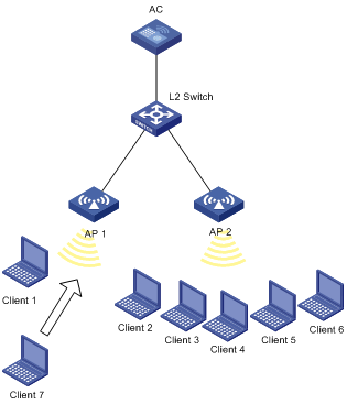
· As shown in Figure 13, all APs operate in 802.11gn mode. Client 1 is associated with AP 1. Client 2 through Client 6 are associated with AP 2.
· Configure session-mode load balancing on the AC. The maximum number of sessions is 5 and the maximum session gap is 4.
· Session-mode load balancing is required on only radio 2 of AP 1 and radio 2 of AP 2. Therefore, add them into a load balancing group.
Configuration procedure
1. Configure APs on the AC:
# Create a WLAN ESS interface.
<AC> system-view
[AC] interface wlan-ess 1
[AC-WLAN-ESS1] port link-type hybrid
[AC-WLAN-ESS1] quit
# Create service template 1 of clear type, configure its SSID as session-balance, and bind WLAN-ESS1 to the service template.
[AC] wlan service-template 1 clear
[AC-wlan-st-1] ssid session-balance
[AC-wlan-st-1] bind wlan-ess 1
[AC-wlan-st-1] authentication-method open-system
[AC-wlan-st-1] service-template enable
[AC-wlan-st-1] quit
# Create an AP template named ap1, and specify its model as WA3628i-AGN, and serial ID as 210235A29G007C000020.
[AC] wlan ap ap1 model WA3628i-AGN
[AC-wlan-ap-ap1] serial-id 210235A29G007C000020
[AC-wlan-ap-ap1] radio 2 type dot11gn
# Bind service template 1 to radio 2 of AP 1.
[AC-wlan-ap-ap1-radio-2] service-template 1
[AC-wlan-ap-ap1-radio-2] radio enable
[AC-wlan-ap-ap1-radio-2] return
# Create an AP template named ap2 and specify its model as WA3628i-AGN, and configure the serial ID as 210235A29G007C000021.
<AC> system-view
[AC] wlan ap ap2 model WA3628i-AGN
[AC-wlan-ap-ap2] serial-id 210235A29G007C000021
[AC-wlan-ap-ap2] radio 2 type dot11gn
# Bind service template 1 to radio 2 of AP 2.
[AC-wlan-ap-ap2-radio-2] service-template 1
[AC-wlan-ap-ap2-radio-2] radio enable
[AC-wlan-ap-ap2-radio-2] return
2. Configure the load balancing mode:
# Enable session-mode load balancing, and configure the maximum number of sessions and the maximum load gap as 5 and 4 respectively.
[AC] wlan rrm
[AC-wlan-rrm] load-balance session 5 gap 4
[AC-wlan-rrm] quit
3. Configure group-based session-mode load balancing:
# Create load balancing group 1.
[AC] wlan load-balance-group 1
# Add radio 2 of AP 1 and radio 2 of AP 2 to the load balancing group.
[AC-wlan-lb-group-1] ap ap1 radio 2
[AC-wlan-lb-group-1] ap ap2 radio 2
Verifying the configuration
Assume Client 7 wants to associate with AP 2. The number of clients associated with radio 2 on AP 2 reaches 5, and the load gap between AP 2 and AP 1 reaches 4, so Client 7 is associated with AP 1.
Configuring group-based traffic-mode load balancing
Network requirements
· As shown in Figure 14, all APs operate in 802.11gn mode. Client 1 and Client 2 are associated with AP 1, and no client is associated with AP 2.
· Configure traffic-mode load balancing on the AC. The traffic threshold is 40% and the maximum traffic gap is 10%.
· Traffic-mode load balancing is required on only radio 1 of AP 1 and radio 1 of AP 2.

Configuration procedure
1. Configure APs on the AC:
# Create a WLAN ESS interface.
<AC> system-view
[AC] interface wlan-ess 1
[AC-WLAN-ESS1] port link-type hybrid
[AC-WLAN-ESS1] quit
# Create service template 1 of clear type, configure its SSID as traffic-balance, and bind WLAN-ESS1 to the service template.
[AC] wlan service-template 1 clear
[AC-wlan-st-1] ssid traffic-balance
[AC-wlan-st-1] bind wlan-ess 1
[AC-wlan-st-1] authentication-method open-system
[AC-wlan-st-1] service-template enable
[AC-wlan-st-1] quit
# Create an AP template named ap1, and specify its model as WA3628i-AGN, and serial ID as 210235A29G007C000020.
[AC] wlan ap ap1 model WA3628i-AGN
[AC-wlan-ap-ap1] serial-id 210235A29G007C000020
[AC-wlan-ap-ap1] radio 2 type dot11gn
# Bind service template 1 to radio 2 of AP 1.
[AC-wlan-ap-ap1-radio-2] service-template 1
[AC-wlan-ap-ap1-radio-2] radio enable
[AC-wlan-ap-ap1-radio-2] return
# Create an AP template named ap2 and specify its model as WA3628i-AGN, and serial ID as 210235A29G007C000021.
<AC> system-view
[AC] wlan ap ap2 model WA3628i-AGN
[AC-wlan-ap-ap2] serial-id 210235A29G007C000021
[AC-wlan-ap-ap2] radio 2 type dot11gn
# Bind service template 1 to radio 2 of AP 2.
[AC-wlan-ap-ap2-radio-2] service-template 1
[AC-wlan-ap-ap2-radio-2] radio enable
[AC-wlan-ap-ap2-radio-2] quit
[AC-wlan-ap-ap2] quit
2. Configure the load balancing mode:
# Enable traffic-mode load balancing and configure the traffic threshold and the maximum load gap as 40% and 10%, respectively.
[AC] wlan rrm
[AC-wlan-rrm] load-balance traffic 40 gap 10
[AC-wlan-rrm] quit
3. Configure group-based traffic-mode load balancing:
# Create load balancing group 1.
[AC] wlan load-balance-group 1
# Add radio 1 of AP 1 and radio 1 of AP 2 to the load balancing group.
[AC-wlan-lb-group-1] ap ap1 radio 1
[AC-wlan-lb-group-1] ap ap2 radio 1
Verifying the configuration
Assume Client 3 wants to associate with AP 1. When the maximum traffic threshold and load gap are reached on radio 2 of AP 1, Client 3 is associated with AP 2.
Band navigation configuration example
Network requirements
As shown in Figure 15, Client 1 through Client 4 try to associate with AP 1, and the two radios of AP 1 operate at 5 GHz and 2.4 GHz respectively. Client 1, Client 2, and Client 3 are dual-band clients, and Client 4 is a single-band (2.4 GHz) client. Configure band navigation to direct clients to different radios of the AP.
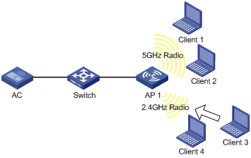
Configuration procedure
# Enable band navigation.
<AC> system-view
[AC] wlan rrm
[AC-wlan-rrm] band-navigation enable
[AC-wlan-rrm] quit
# Create a WLAN-ESS interface.
[AC] interface wlan-ess 1
[AC-WLAN-ESS1] port link-type hybrid
[AC-WLAN-ESS1] quit
# Create service template 1 of clear type, configure its SSID as band-navigation, and bind WLAN-ESS1 to the service template.
[AC] wlan service-template 1 clear
[AC-wlan-st-1] ssid band-navigation
[AC-wlan-st-1] bind wlan-ess 1
# Disable fast association. (Optional. By default, fast association is disabled.)
[AC-wlan-st-1] undo fast-association enable
[AC-wlan-st-1] service-template enable
# Create an AP template named ap1, and specify its model as WA2620E-AGN, and serial ID as 260235A29G007C000020.
[AC] wlan ap ap1 model WA2620E-AGN
[AC-wlan-ap-ap1] serial-id 210235A29G007C000020
# Bind service template 1 to radio 1 of AP 1.
[AC-wlan-ap-ap1] radio 1 type dot11an
[AC-wlan-ap-ap1-radio-1] service-template 1
[AC-wlan-ap-ap1-radio-1] radio enable
[AC-wlan-ap-ap1-radio-1] quit
# Bind service template 1 to radio 2 of AP 1.
[AC-wlan-ap-ap1] radio 2 type dot11gn
[AC-wlan-ap-ap1-radio-2] service-template 1
[AC-wlan-ap-ap1-radio-2] radio enable
[AC-wlan-ap-ap1-radio-2] return
# Configure the band navigation load balancing session threshold as 2, and session gap as 1.
<AC> system-view
[AC] wlan rrm
[AC-wlan-rrm] band-navigation balance session 2 gap 1
Verifying the configuration
Client 1 and Client 2 are associated with the 5 GHz radio of AP 1, and Client 4 can only be associated with the 2.4 GHz radio of AP 1. Because the number of clients on the 5 GHz radio has reached the upper limit 2, and the gap between the number of clients on the 5 GHz radio and 2.4 GHz radio has reached the session gap 1, Client 3 is associated with the 2.4 GHz radio of AP 1.