- Table of Contents
-
- H3C WX3024E Wireless Switch Installation Guide-6W106
- 00-Preface
- 01-Text
- 02-Appendix A Technical Specifications
- 03-Appendix B Transceiver Module Specifications
- 04-Appendix C Installing a Lightning Arrester for a Network Interface
- 05-Appendix D Installing a Lightning Arrester for AC Power
- 06-Appendix E Maintaining Software
- Related Documents
-
| Title | Size | Download |
|---|---|---|
| 01-Text | 1.99 MB |
General safety recommendations
Examining the installation site
Installing the switch in a 19-inch rack
Installing the switch by using front and rear mounting brackets
Installing the switch by using front mounting brackets and a rack shelf
Installing the switch by using front mounting brackets and slide rails
Mounting the switch on a workbench
Grounding the switch with a grounding strip (recommended)
Grounding the switch with a grounding conductor buried in the earth ground
Grounding the switch through the PE wire of an AC power cord
Connecting an AC power cord to the switch
Connecting the switch to an RPS
Connecting the interface cables
Connecting the Ethernet cables
Installing/removing an interface card
Installing an XFP interface card
Removing an XFP interface card
Starting and configuring the switch·
Setting up a configuration environment
Connecting the switch to a configuration terminal
Configuration terminal problems
Overview
The H3C WX3024E wireless switch incorporates the functions of WLAN access controllers and Gigabit Ethernet switches. The WX3024E wireless switch provides Gigabit ports, support power over Ethernet plus (PoE+) and 802.11a/b/g/n access points (APs), and has a maximum output power of 30 W per port. Together with H3C fit APs, the WX3024E can implement wireless LAN (WLAN) deployment and provide many switching features.
The dimensions and weight of the WX3024E are as follows:
· Dimensions (H × W × D)—43.6 × 440 × 429 mm (1.7 × 17.3 × 16.9 in)
· Weight—7.2 kg (15.87 lb)
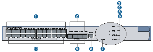
The WX3024E provides twenty-four 10/100/1000Base-T Ethernet ports, four 1000Base-X SFP ports, and one console port on its front panel.
Figure 1 Front panel of the WX3024E
|
(2) 1000Base-X SFP port LEDs |
|
|
(3) Status LED (PWR) |
(4) RPS LED (RPS) |
|
(5) Expansion slot LED (MOD1) |
(6) Expansion slot LED (MOD2) |
|
(7) PoE/PoE+ LED (Mode) |
(8) Console port |
|
(9) 1000Base-X SFP ports |
(10) 10/100/1000 Base-T Ethernet ports |
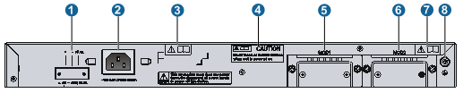
The WX3024E provides an AC power receptacle, a DC power receptacle, and two expansion slots for 10 GE interface cards on its rear panel.
Figure 2 Rear panel of the WX3024E
|
(1) DC power receptacle |
(2) AC power receptacle |
|
(3) OPEN BOOK mark |
(4) CAUTION mark |
|
(5) 10 GE port slot 1 |
(6) 10 GE port slot 2 |
|
(7) OPEN BOOK mark |
(8) Grounding screw |
Refer to relevant sections before performing the corresponding operations for the OPEN BOOK and CAUTION marks.
Table 1 Meanings of the OPEN BOOK mark
|
Operation |
Related section |
|
Connect the power cord |
|
|
Ground the switch |
|
|
Install optional interface cards |
Power supply
|
|
NOTE: The WX3024E supports several power input modes: AC input only, DC input only, and concurrent AC and DC inputs. When AC and DC inputs are used concurrently, they serve as backup for each other. |
AC power supply
Table 2 AC power supply specifications
|
Item |
Description |
|
Rated voltage range |
100 to 240 VAC, 50/60 Hz |
|
Maximum voltage range |
90 to 264 VAC, 47 to 63 Hz |
|
Maximum system power consumption (without external PoE devices) |
90 W |
|
Minimum power consumption |
53 W |
DC power supply
DC voltage range: –52V to –55 V
Only Redundancy Power Supply (RPS) is supported for DC power supply. In the case of RPS input, the WX3024E can supply 720 W power to the PoE devices connected to it. The maximum output power for each port is 30 W.
|
|
NOTE: · Use only H3C-recommended RPS 1600 for DC power supply. RPS 1600 and RPS cables are optional. Order them by yourself. · The DC power cords should be shorter than 3 meters (9.84 ft.) to minimize voltage attenuation. · For how to install an RPS, see the chapter “Installing the switch (page 17).” |
Table 3 DC power cord description
|
Item |
Length |
Description |
|
CAB-RPS PoE-2m-JD5 |
2 m (6.56 ft) |
JD5 DC power cord |
PoE power supply
The WX3024E supports Power over Ethernet (PoE) to provide –48 VDC supply to attached powered devices (PDs), such as IP phones, WLAN APs, and security and Bluetooth APs, through twisted pair cables.
|
|
CAUTION: Only the H3C-recommended external PoE power supply (RPS) can be used as the DC input, rather than the –48 VDC power supply of the equipment room, which may cause device damage. |
· As a power sourcing equipment (PSE), the WX3024E supports the IEEE 802.3at standard while being compatible with some PoE powered devices that do not comply with the 802.3at standard.
· The WX3024E provides power supply through fixed electrical Ethernet ports, with the maximum power transmission distance of 100 meters (328.08 ft).
· Each Ethernet port of the WX3024E provides a maximum of 30 W output power to the attached PoE powered devices. In the case of AC input, the maximum output power with full load of the WX3024E is 370 W; in the case of RPS input, the maximum output power of the WX3024E is 30 W × 24 ports = 720 W (The RPS output power should be at least 740 W).
Fans
The WX3024E is equipped with five fans: two for heat dissipation of the main board and three on the power supply for heat dissipation of the power supply system.
Safety recommendations
To avoid any equipment damage or bodily injury caused by improper use, read the following safety recommendations before installation. Note that the recommendations do not cover every possible hazardous condition.
General safety recommendations
· Keep the chassis clean and dust-free.
· Make sure that the ground is dry and flat and anti-slip measures are in place.
· Do not place the switch in a moist area and avoid liquid surrounding the switch.
· Keep the chassis and installation tools away from walk areas.
· Do not wear loose clothing, jewelry (for example, necklace) or any other objects that could get caught in the chassis when you install and maintain the switch.
Safety with electricity
· Clear the work area of possible hazards, such as ungrounded power extension cables, missing safety grounds, and wet floors.
· Locate the emergency power-off switch in the room before installation. Shut the power off at once in case any accident occurs.
· Unplug all the external cables (including power cords) before moving the chassis.
· Do not work alone when the switch has power.
· Always check that the power has been disconnected.
Safety with switch moving
To move a WX3024E switch:
· Remove all the external cables (including the power cords) before moving the chassis.
· Move the switch carefully.
ESD prevention
To prevent the electronic components from being damaged by the electrostatic discharge (ESD), take the following precautions:
· Hold an interface card by its edges. Do not touch any electronic components or printed circuit.
· Put an interface card into an antistatic bag.
· Make sure the switch is well grounded. For how to ground the switch, see the chapter “Installing the switch (page 14).”
· Always wear an ESD-preventive wrist strap when installing components.
To use the ESD-preventive wrist strap:
1. Wear the wrist strap on your wrist.
2. Lock the wrist strap tight around your wrist to keep good contact with the skin.
3. Attach the wrist strap to the chassis with the alligator clips.
4. Make sure that the ESD-preventive wrist strap is well grounded.
Figure 3 Use an ESD-preventive wrist strap
|
|
NOTE: No ESD-preventive wrist strap is provided with the switch. Prepare it by yourself. |
Safety with laser
The WX3024E switch is a class 1 laser product.
|
|
WARNING! Do not stare into any fiber port when the switch has power. The laser light emitted from the optical fiber may hurt your eyes. |
Examining the installation site
The WX3024E switch must be used indoors. To ensure normal operation and long service life of your switch, install it in an environment that meets the requirements described in the following subsections.
Weight support
Evaluate the floor loading as compared to the actual weight of the switch and its accessories, and make sure that the floor can support the weight of the cabinet and the switch chassis.
Temperature/humidity
Maintain appropriate temperature and humidity in the equipment room.
· Lasting high relative humidity can cause poor insulation, electricity creepage, mechanical property change of materials, and metal corrosion.
· Lasting low relative humidity can cause washer contraction and ESD and bring problems including loose captive screws and circuit failure.
· High temperature can accelerate the aging of insulation materials and significantly lower the reliability and lifespan of the switch.
Table 4 Temperature/humidity requirements
|
Item |
Range |
|
Operating temperature |
0°C to 45°C (32°F to 113°F) |
|
Operating humidity (noncondensing) |
5% to 95% |
Cleanness
Dust buildup on the chassis may result in electrostatic adsorption, which causes poor contact of metal components and contact points, especially when indoor relative humidity is low. In the worst case, electrostatic adsorption can cause communication failure.
Table 5 Dust concentration limit in the equipment room
|
Substance |
Concentration limit (particles/cu m) |
|
Dust particles |
≤ 3 x 10⁴ (No visible dust on desk in three days) |
|
NOTE: Dust particle diameter ≥ 5 µm |
|
The equipment room must also meet strict limits on salts, acids, and sulfides to eliminate corrosion and premature aging of components.
Table 6 Harmful gas limits in an equipment room
|
Gas |
Max. (mg/m3) |
|
SO2 |
0.2 |
|
H2S |
0.006 |
|
NH3 |
0.05 |
|
Cl2 |
0.01 |
Grounding
Using a good grounding system to protect your switch against lightning shocks, interferences, and ESD is essential to the operating reliability of your switch. Make sure that the resistance between the chassis and the ground is less than 1.5 ohm. For how to ground the switch, see the chapter “Installing the switch (page 14).”
Power supply
To satisfy the power supply requirements of the WX3024E:
1. Calculate the system power consumption
The total power consumption of a WX3024E depends on the number of PDs connected to it. For more information about the system power consumption, see the chapter “Product overview (page 3).”
2. Check that the power supply system on the installation site satisfies the power input of the power supply modules.
Make sure the power supply system of the installation site is steady and can satisfy the input requirements of the power supply modules such as rated voltage.
Space
For adequate ventilation and ease of maintenance, adhere to the following requirements:
· Adequate space is reserved at the air inlet and exhaust vents for heat dissipation. H3C recommends you to reserve a space greater than 10 cm (3.94 in).
· The rack or workbench has a good ventilation system.
EMI
All electromagnetic interference (EMI) sources, from outside or inside of the switch and application system, adversely affect the switch in a conduction pattern of capacitance coupling, inductance coupling, electromagnetic wave radiation, or common impedance (including the grounding system) coupling. To prevent EMI, take the following actions:
· If AC power is used, use a single-phase three-wire power receptacle with protection earth (PE) to filter interference from the power grid.
· Keep the switch far away from radio transmitting stations, radar stations, and high-frequency devices.
· Use electromagnetic shielding, for example, shielded interface cables, when necessary.
· Route interface cables only indoors to prevent signal ports from getting damaged by over-voltage or over-current caused by lightning strikes.
Installation tools
· Flat-blade screwdriver
· Phillips screwdriver (P2-150mm)
· ESD-preventive wrist strap
All these installation tools are user supplied.
Installing the switch
|
CAUTION: Keep the tamper-proof seal on a mounting screw on the chassis cover intact, and if you want to open the chassis, contact your local HP agent for permission. Otherwise, H3C shall not be liable for any consequence caused thereby. |
Installing the switch in a 19-inch rack
The WX3024E switch can be installed in a standard 19-inch rack, and the installation falls into the following scenarios:
· Installing the switch with front and rear mounting brackets.
· Installing the switch with front mounting brackets and a rack shelf.
· Installing the switch with front mounting brackets and slide rails.
|
|
NOTE: · The front mounting brackets can be used only for fixing the switch, rather than weight-bearing. · The slide rails provided by H3C are suitable only for H3C standard racks with the depth of 1000 mm (39.37 in). You need to seek other supporting means if your rack has a different depth. |
Mounting brackets
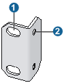
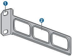
Figure 4 Front mounting bracket
|
(1) Screw holes for fixing the front mounting bracket onto the rack (using M6 screws) |
|
(2) Screw hole for fixing the front mounting bracket to the switch chassis |
Figure 5 Rear mounting bracket
|
(1) Screw holes for fixing the rear mounting bracket onto the rack (using M6 screws) |
|
(2) Heat dissipation holes |
Slide rails
The slide rails are optional components that need to be separately ordered.
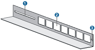
Figure 6 Slide rail
|
(1) Slot hole for fixing the slide rail onto the rear bracket of the rack. It allows adjustment of the switch mounting screw position according to the switch position. |
|
(2) Heat dissipation holes. Holes for heat dissipation between the switch and the rack. |
|
(3) Slot hole for fixing the slide rail onto the front bracket of the rack. |
Installing the switch by using front and rear mounting brackets
To install the switch by using front and rear mounting brackets:
1. Wear an ESD-preventive wrist strap and make sure that the rack is sturdy and properly grounded.
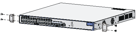
2. Use the screws packed with the front mounting brackets to fix the front mounting brackets on both sides of the switch. See Figure 7.
Figure 7 Attach the front mounting brackets to both sides of the switch
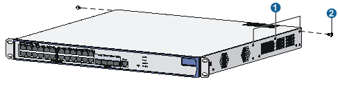
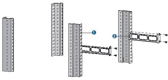
3. Fix the weight-bearing screws packed with the rear mounting brackets on both sides of the switch. See Figure 8.
Figure 8 Install the weight-bearing screws
|
(1) Three holes for mounting the weight-bearing screw (select one as needed) |
|
|
(2) Weight-bearing screw |
|
|
|
NOTE: There are three screw holes on each side of the switch for the weight-bearing screws. You can select a proper location as needed. The rear mounting brackets will support the weight of the switch through firm contact with the weight-bearing screws. |
4. Determine the switch installation position in the rack and use screws and cage nuts to fix the rear mounting brackets on the rear square-holed brackets of the rack. See Figure 9.
Figure 9 Install rear mounting brackets
|
(1) Rear square-holed brackets |
(2) Rear mounting bracket |
5. Hold the bottom of the switch with one hand and the front part with the other hand, and gently push the switch into the rack. See Figure 10.
Figure 10 Install the switch using front and rear mounting brackets (I)
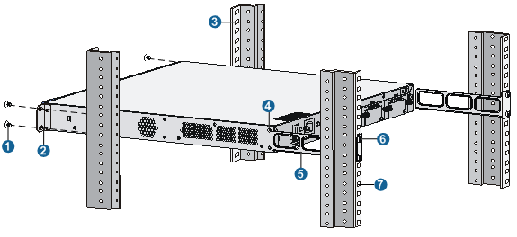
|
(1) Screw for fixing the front mounting bracket |
(2) Front mounting bracket |
|
(3) Front square-holed bracket |
(4) Weight-bearing screw |
|
(5) Rear mounting bracket |
(6) Screw for fixing the rear mounting bracket |
|
(7) Rear square-holed bracket |
|
|
|
CAUTION: After pushing the switch into the rack, make sure that the upper edges of the rear mounting brackets fixed on the rack have close contact with the weight-bearing screws on the switch. See Figure 11. |
Figure 11 Install the switch using front and rear mounting brackets (II)
|
(1) Rear mounting bracket |
(3) Rear square-holed bracket |
6. Fix the front mounting brackets on the front square-holed brackets of the rack with screws and cage nuts. Make sure that the switch is firmly fixed on the rack through the front and rear mounting brackets. See Figure 12.
Figure 12 Install the switch using front and rear mounting brackets (III)
|
(1) Front square-holed bracket |
Installing the switch by using front mounting brackets and a rack shelf
The rack shelf is an optional component that needs to be separately ordered if needed.
To install the switch in a rack using front mounting brackets and a rack shelf:
1. Wear an ESD-preventive wrist strap and check that the rack is sturdy and properly grounded.
2. Use the screws packed with the front mounting brackets to fix the front mounting brackets on both sides of the switch. See Figure 7.
3. Fix the rack shelf on the rack (see Figure 13. This figure is for reference only and may differ from the actual installation on your rack).
Figure 13 Install a rack shelf
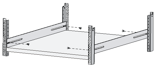
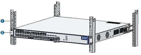
4. Place the switch horizontally on the rack shelf, push it into the rack along the rack shelf, and fix the front mounting brackets onto the front square-holed brackets of the rack using the screws and cage nuts. See Figure 14.
Figure 14 Install the switch using front mounting brackets and a rack shelf
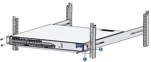
|
(1) Front mounting bracket |
(2) Front square-holed bracket |
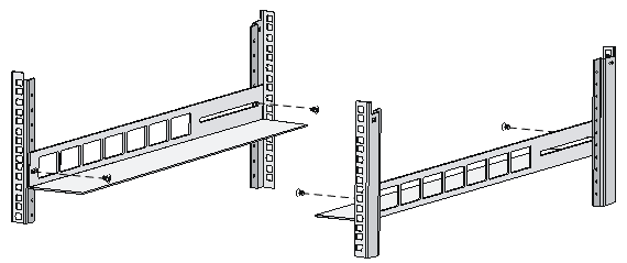
Installing the switch by using front mounting brackets and slide rails
To install the switch with front mounting brackets and slide rails:
1. Wear an ESD-preventive wrist strap and verify that the rack is sturdy and properly grounded.
2. Use the screws packed with the front mounting brackets to fix the front mounting brackets on both sides of the switch. See Figure 7.
3. Fix the slide rails on both sides of the rack with M5 self-tapping screws (see Figure 15. This figure is for reference only and may differ from the actual installation on your rack and slide rails).
4. Hold the switch by both sides of it and gently push it into the rack along the slide rails (see Figure 16). Verify that the bottom of the switch is in firm contact with the slide rails.
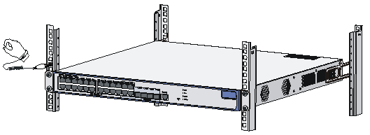
Figure 16 Install the switch using front mounting brackets and slide rails
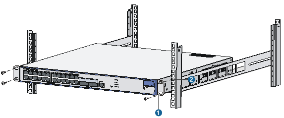
|
(1) Front mounting bracket |
(2) Front square-holed bracket |
5. Fix the front mounting brackets on the front square-holed brackets of the rack using the M6 screws and cage nuts. Make sure that the switch is firmly fixed on the rack through the front mounting brackets and slide rails.
|
|
NOTE: Keep a distance of 1 U (44.45 mm/1.75 in) between two devices to ensure good heat dissipation. |
Mounting the switch on a workbench
To mount the switch on a workbench, check the following:
· The workbench is sturdy and well grounded.
· The workbench is a well-ventilated environment. Keep at least 10 cm (3.94 in) clearance around the switch for heat dissipation.
· No heavy object is placed on the switch.
· At least 15 mm (0.59 in) distance is provided between two devices when they are stacked one above the other.
Grounding the switch
|
|
WARNING! Correctly connecting the switch grounding cable is crucial to lightning protection and EMI protection. |
The power input end of the switch has a noise filter, whose central ground is directly connected to the chassis to form the chassis ground (commonly known as PGND). You must securely connect this chassis ground to the earth so the faradism and leakage electricity can be safely released to the earth to minimize EMI susceptibility of the switch.
You can ground the switch in one of the following ways, depending on the grounding conditions available at the installation site:
· Grounding the switch with a grounding strip (recommended)
· Grounding the switch with a grounding conductor buried in the earth ground
· Grounding the switch through the PE wire of an AC power cord
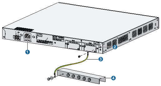
Grounding the switch with a grounding strip (recommended)
Attach one end of the yellow-green grounding cable of the switch to the grounding post on the chassis with a grounding screw and the other end to the grounding terminal on the grounding strip and fasten the nut.
Figure 17 Connect the grounding cable to a grounding strip
|
(1) AC power receptacle |
(2) Grounding screw |
|
(3) Grounding cable |
(4) Grounding strip |
|
|
WARNING! Connect the grounding cable to the grounding system in the equipment room. Do not connect it to a fire main or lightning rod. |
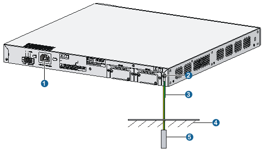
Grounding the switch with a grounding conductor buried in the earth ground
If the installation site has no grounding strips, but earth ground is available, hammer a 0.5 m (1.64 ft) or longer angle iron or steel tube into the earth ground to serve as a grounding conductor.
Weld the yellow-green grounding cable to the angel iron or steel tube and treat the joint for corrosion protection.
Figure 18 Ground the switch by burying the grounding conductor into the earth ground
|
(1) AC power receptacle |
(2) Grounding screw |
(3) Grounding cable |
|
(5) Angle iron |
(4) Earth |
|
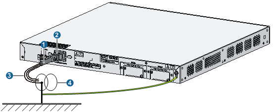
Grounding the switch through the PE wire of an AC power cord
|
|
CAUTION: Use this method only when the switch is AC powered. |
If the installation site has no grounding strips or earth ground, you ground an AC-powered switch through the protective earth (PE) wire of the power cord, and check that the ground contact in the power outlet is well connected to the ground in the power distribution room or on the AC transformer side.
Figure 19 Ground the switch through the PE wire of an AC power cord
|
(1) Three-core AC power cord |
(2) AC power receptacle |
|
(3) PE wire |
(4) Power transformer |
|
(5) Earth |
|
Connecting the power cord
Connecting an AC power cord to the switch
|
|
NOTE: The power cords may vary with different standards of different countries, so you may need to select a bail latch as needed. |
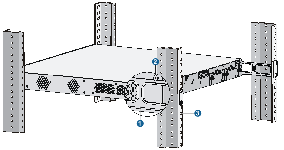
To connect the AC power cord:
1. Verify that the chassis ground is correctly connected to the earth ground.
2. Install the bail latch onto the switch and pivot the bail latch up.
3. Plug one end of the power cord to the AC power receptacle on the rear panel of the chassis and plug the other end to the AC power source.
4. Place the bail latch over the AC power cord to secure the plug in place.
Figure 20 Connect the AC power cord
|
(1) Rear panel |
(2) Bail latch holder |
|
(3) Bail latch |
(4) AC power cord |
5. Check the system LED (PWR) on the front panel of the switch. If the LED is on, the AC power input is normal.
|
|
NOTE: The bail latch prevents the power cord from accidentally falling off. |
Connecting the switch to an RPS
The RPS power supply is optional. The WX3024E supports RPS power supply model RPS 1600.
To connect the switch to an RPS:
1. Check that the switch is powered off and the RPS is switched off.
2. Use a Philips screwdriver to remove the screws on the cover on the DC power receptacle and take off the cover.
3. Connect the RPS power cord to the DC power receptacle on the chassis.
4. Turn the strain release screws on the RPS power cord clockwise so that the RPS power cord plug is firmly seated in the DC power receptacle, and then fasten the strain release screws.
5. Connect the other end of the RPS power cord to an output interface of the RPS.
Figure 21 Connect the switch to an RPS
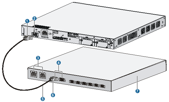
|
(1) RPS power cord plug for the DC power receptacle |
(2) DC power receptacle |
|
(3) AC power input interfaces of the RPS unit |
(4) DC output interfaces of the RPS unit |
|
(5) RPS power cord |
(6) RPS power cord plug for the RPS output |
|
(7) RPS |
|
6. Check the RPS LED on the front panel of the switch. LED ON means the RPS unit is correctly connected.
|
|
CAUTION: Check that the grounding cable is properly connected before powering on the switch. |
Connecting the interface cables
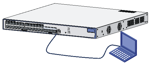
Connecting the console cable
1. Prepare a configuration terminal
The configuration terminal can be an ASCII terminal with an RS232 serial port or a PC. The description in this section assumes that you use a PC as the configuration terminal.
2. Connect the console cable
a. Plug the DB-9 female connector of the console cable to the serial port of the PC.
b. Connect the RJ-45 connector to the console port of the switch.
|
|
NOTE: Identify the mark on the console port and make sure that you are connecting to the correct port. |
Figure 22 Connect the console cable
|
|
NOTE: If the switch has been powered on, connect the console cable to the PC before connecting to the switch, and when you disconnect the cable, first disconnect from the switch. |
Connecting the Ethernet cables
Connecting a copper Ethernet port
To connect a copper Ethernet port:
1. Connect one end of the Ethernet cable to the copper Ethernet port on the switch and the other end to an Ethernet port of the peer switch.
2. After powering on the switch, check the LEDs of the fixed copper Ethernet port.
For more information about the LED description, see the chapter “Appendix A Technical specifications.”
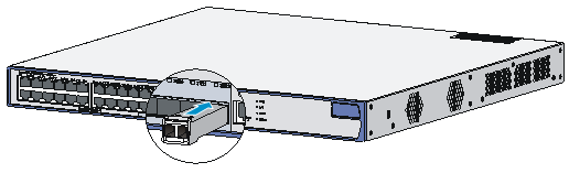
Connecting a fiber Ethernet port
To connect a 1000 Mbps fiber port:
1. Identify the top side of the SFP module, and gently insert it into the socket.
Figure 23 Insert a transceiver module
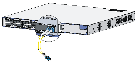
2. Identify the Rx and Tx ports on the transceiver module and plug the two LC connectors at one end of the fibers into the Rx and Tx ports.
3. Plug the LC connectors at the other end of the fiber into the Tx and Rx ports on a fiber port on the peer device.
Figure 24 Connect fiber connectors
4. After powering on the switch, check the SFP port LEDs.
For more information about the SFP LEDs, see the chapter “Appendix A Technical specifications.”
|
|
WARNING! When you connect a fiber, note the following guidelines: · Never bend or curve a fiber with a fierce force. The bend radius of a fiber must be not less than 10 cm (3.94 in). · Make sure the TX and RX ports on a transceiver module are correctly connected. · Keep the fiber end clean. |
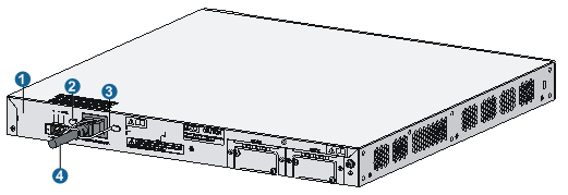
Installing/removing an interface card
|
|
NOTE: The interface cards of the WX3024E are not hot swappable. |
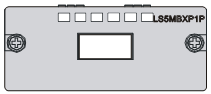
10-Gigabit small form-factor pluggable (XFP) interface cards are used for copper-to-fiber and fiber-to-copper conversion in optical signal transmission. An XFP interface card requires fiber cables with LC connectors.
Figure 25 Front panel
Installing an XFP interface card
To install an XFP interface card in an interface card slot:
1. Wear an ESD-preventive wrist strap and make sure it makes good skin contact and is well grounded.
2. Unpack the XFP interface card.
3. Loosen the captive screws on the filler panel over the interface card slot with a Phillips screwdriver and remove the filler panel.
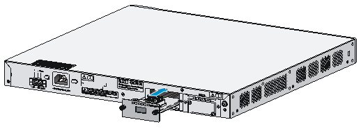
4. Squeezing the XFP interface card by the captive screws on the front panel, push the XFP interface card steadily into the slot along the slide rails until it is firmly seated in the switch.
Figure 26 Install an XFP interface card
5. Fasten the captive screws on the XFP interface card to secure it in place.
|
|
NOTE: · Keep the removed filler panel properly for future use. · Do not over-tighten the captive screws on the front panel of the interface card. |
Removing an XFP interface card
To remove and XFP interface card:
1. Wear an ESD-preventive wrist strap and make sure it makes good skin contact and is well grounded.
2. Use a Phillips screwdriver to completely loosen the captive screws at both sides of the interface card.
3. Pull the interface card outward until it is completely out of the switch chassis.
|
|
CAUTION: When you install or remove an interface card, note the following guidelines: · Do not use excessive force in the operation and do not touch the surface-mounted components directly with your hands. · After removing an interface card, if the slot is to remain empty, install a filler panel to prevent dust and ensure normal ventilation in the switch. |
Verifying the installation
During the installation of the switch, always verify the installation before powering on the switch:
· The power supply system meets the switch requirements.
· The grounding cable is correctly connected.
· Both the console cable and power cords are correctly connected.
· All interface cables are routed indoors. If outdoor routing of cables cannot be avoided, check that network port lightning arrestors and an AC power supply lightning arresters have been correctly installed. For more information, see the chapters “Appendix B Transceiver module specifications” and “Appendix C Installing a lightning arrester for a network interface.”
Starting and configuring the switch
Setting up a configuration environment
Connecting the switch to a configuration terminal
For more information about connecting the switch to a configuration terminal, see the chapter “Installing the switch (page 18).”
Setting terminal parameters
To configure and manage the switch, you must run a terminal emulator program on the console terminal.
The following are the required terminal settings:
· Bits per second—9,600
· Data bits—8
· Parity—None
· Stop bits—1
· Flow control—None
· Emulation—VT100
To set terminal parameters, for example, on a Windows XP HyperTerminal:
1. Select Start > All Programs > Accessories > Communications > HyperTerminal.
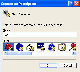
The Connection Description dialog box appears.
2. Enter the name of the new connection in the Name field and click OK.
Figure 27 Connection description
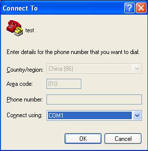
3. Select the serial port to be used from the Connect using list, and click OK.
Figure 28 Set the serial port used by the HyperTerminal connection
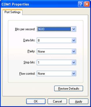
4. Set Bits per second to 9600, Data bits to 8, Parity to None, Stop bits to 1, and Flow control to None, and click OK.
Figure 29 Set the serial port parameters
|
|
NOTE: To restore the default settings, click Restore Defaults. |
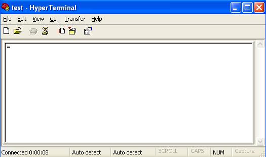
5. Select File > Properties in the HyperTerminal window.
Figure 30 HyperTerminal window
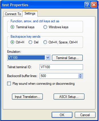
6. On the Settings tab, set the emulation to VT100 and click OK.
Figure 31 Set the terminal emulation
Powering on the switch
Verification before power-on
Before you power on the switch, verify that:
· The power cord and grounding cable are properly connected.
· The input power voltage meets the requirement of the switch.
· The console cable is properly connected, the terminal or PC used for configuration has started, and the configuration parameters have been set.
Boot process
Power on the switch, and you can see the following information:
System is starting...
Booting Normal Extend BootWare....
***************************************************************************
* *
* H3C WX3024E BootWare, Version 1.02 *
* *
***************************************************************************
Copyright (c) 2004-2010 Hangzhou H3C Technologies Co., Ltd.
Compiled Date : Nov 23 2010
CPU Type : XLS208
CPU L1 Cache : 32KB
CPU Clock Speed : 750MHz
Memory Type : DDR2 SDRAM
Memory Size : 512MB
Memory Speed : 533MHz
BootWare Size : 768KB
Flash Size : 1024MB
CPLD Version : 004
PCB Version : Ver.A
BootWare Validating...
Press Ctrl+B to enter extended boot menu...
Press Ctrl + B at the prompt within four seconds to access the Boot menu, or wait for the system to automatically start up. To access the BootWare menu after the system software image files are decompressed, you must restart the switch.
Starting to get the main application file--flash:/wx3000.bin!...........................
.............................................
The main application file is self-decompressing ........................................
.....................................................................................
.....................................................................................
.....................................................................................
.....................................................................................
.....................................................................................
.....................................................................................
.....................................................................................
.....................................................................................
.....................................................................................
.....................................................................................
.........Done!
System application is starting...
User interface aux0 is available.
Press ENTER to get started.
Press Enter at the prompt, and you can configure the switch when the prompt <H3C> appears.
|
|
NOTE: During the startup process, the CPLD will be automatically upgraded to the latest version, if any. The system will display “The board cpld update successfully, please repower device.” after the upgrade process. At this prompt, power off and restart the switch so that the new CPLD version takes effect. |
Power supply failure
You can look at the RPS LED and PWR LED of the switch to identify a power system failure.
· The RPS LED is off if DC power input is abnormal or there is no DC input.
· The RPS LED is steady yellow or the PWR LED is off if AC power input is abnormal or there is no AC power input.
Verify the following items:
· The switch power cord is properly connected;
· The power input to the switch meets the requirements.
Configuration terminal problems
If the configuration environment setup is correct, the configuration terminal displays booting information when the switch is powered on. If the setup is incorrect, the configuration terminal displays nothing or garbled text.
No terminal display
If the configuration terminal displays nothing when the switch is powered on, verify the following items:
· The power supply is supplying power to the switch.
· The console cable is properly connected.
· The console cable has no problem and the terminal settings are correct.
Garbled terminal display
If terminal display is garbled, verify that the following settings are configured for the terminal, for example, HyperTerminal:
· Baud rate—9,600
· Data bits—8
· Parity—none
· Stop bits—1
· Flow control—none
· Emulation—VT100
Software loading failure
If software loading fails, the system runs the old version of the software. In this case, check if the physical ports are properly connected.
· If the ports are not properly connected, reconnect them correctly and restart the loading process.
· If the ports are properly connected, check the loading process information displayed on HyperTerminal for input errors. In case of any input errors, restart the loading process with correct inputs.
Input errors include the following:
· A baud rate other than 9600 bps selected for BootWare loading using XMODEM.
· An improper baud rate setting in HyperTerminal.
· A wrong IP address, file name, or TFTP Server work path specified for software loading using TFTP.
· A wrong IP address, file name, username, or password specified for software loading using FTP.
If the case cannot be located, contact your local dealer for help.