- Table of Contents
-
- H3C WX3024E Wireless Switch Installation Guide-6W106
- 00-Preface
- 01-Text
- 02-Appendix A Technical Specifications
- 03-Appendix B Transceiver Module Specifications
- 04-Appendix C Installing a Lightning Arrester for a Network Interface
- 05-Appendix D Installing a Lightning Arrester for AC Power
- 06-Appendix E Maintaining Software
- Related Documents
-
| Title | Size | Download |
|---|---|---|
| 02-Appendix A Technical Specifications | 131.85 KB |
Fixed ports
Table 1 Fixed port specifications
|
Item |
Description |
|
Console port |
1 console port: 9600 bps (default) to 115200 bps |
|
Ethernet ports |
24 × 10/100/1000 Base-T Ethernet ports |
|
SFP ports |
4 × 1000Base-X SFP ports. Each of these ports and the corresponding 10/100/1000Base-T Ethernet port numbered in the range of 21 to 24 to form a combo interface. |
Console port
The WX3024E provides an RS-232 asynchronous serial console port, which can be used to connect a background terminal (a PC, for example) for system debugging, configuration, maintenance, management, and software loading.
A console cable is an 8-core shielded cable, with a crimped RJ-45 connector at one end for connecting to the console port of the switch, and a DB-9 female connector at the other end for connecting to the serial port on the console terminal.
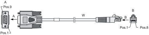
Table 2 Console cable pinouts
|
RJ-45 pin |
Signal |
Direction |
DB-9 pin |
|
1 |
RTS |
← |
7 |
|
2 |
DTR |
← |
4 |
|
3 |
TXD |
← |
3 |
|
4 |
CD |
→ |
1 |
|
5 |
GND |
— |
5 |
|
6 |
RXD |
→ |
2 |
|
7 |
DSR |
→ |
6 |
|
8 |
CTS |
→ |
8 |
Ethernet ports
Ethernet ports
The WX3024E provides twenty-four 10/100/1000Base-T Ethernet ports and four 1000Base-X SFP ports.
Each SFP port and the corresponding 10/100/1000Base-T Ethernet port jointly form a combo interface. Only one of the two ports of a combo interface can be used at a time.
Table 3 SFP and copper Ethernet ports of the WX3024E that form the combo interfaces
|
1000Base-X SFP port |
10/100/1000Base-T Ethernet port |
|
25 |
22 |
|
26 |
24 |
|
27 |
21 |
|
28 |
23 |
The copper Ethernet port status LEDs are above the RJ-45 sockets. The triangular pointer above each LED indicates which port the LED is for. The fiber Ethernet ports of the WX3024E support 1000 Mbps full duplex. The fiber port status LEDs are above the 1000Base-X SFP ports, each indicating the status of the corresponding fiber port.
RJ-45 connectors
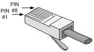
The 10/100/1000M copper Ethernet ports of the WX3024E work with Category-5 twisted pair cables with RJ-45 connectors, as shown in Figure 2.
LC connectors
A fiber connector is mainly used for the removable connection between fiber tunnels. This facilitates the testing and maintenance of the fiber system and makes fiber inter-connections more flexible.
The WX3024E supports only LC connectors.
Figure 3 LC connector

|
|
NOTE: · Before you connect a networking device by using optical fibers, make sure that the fiber connectors work with the transceiver modules. · Before connecting fiber cables, make sure that the optical power of the receiver end does not exceed the upper threshold of the receiving optical power of the transceiver module; otherwise, the transceiver module may be damaged. For the optical power specifications of the receiver end, see the chapter “Appendix B Transceiver module specifications.” |
LEDs
|
LED |
Mark |
Status |
Description |
|
Power status LED (green/yellow/red) |
PWR |
Steady green |
The system is going through the power on self test (POST) or downloading software. |
|
Flashing green (1 Hz) |
The system is working properly. |
||
|
Steady red |
The system failed to pass the POST or has detected a serious fault. |
||
|
Steady yellow (1 Hz) |
At least one port has failed the POST or detected a minor fault. |
||
|
Off |
No AC input is present. |
||
|
PoE/PoE+ status LED (green/yellow) |
Mode |
Steady green |
The PoE/PoE+ is operational. |
|
Flashing green (3 Hz) |
PoE/PoE+ supply is not available because the maximum output power of the port is exceeded or the remaining power is insufficient. |
||
|
Steady yellow |
The ports cannot provide PoE/PoE+ supply due to an over-temperature, over-voltage, or under-voltage protection shutdown of the PoE/PoE+ system. |
||
|
Flashing yellow (3 Hz) |
At least one port failed to pass the POST; if the PoE sub-board is in position, it may be caused by a UART communication failure or some other self test failure. |
||
|
Off |
No PoE/PoE+ supply. |
||
|
RPS status LED (yellow/green) |
RPS |
Steady green |
Both AC and DC inputs are normal. |
|
Steady yellow |
The AC input is abnormal or no AC input is present, while the DC input is normal. |
||
|
Off |
No DC input is present. |
||
|
10/100/1000 Base-T Ethernet port status LED (yellow/green) |
— |
Steady green |
A 1000 Mbps link is present on the port. |
|
Flashing green (33 Hz) |
The port is receiving or transmitting data at 1000 Mbps. |
||
|
Steady yellow |
A 10/100 Mbps link is present on the port. |
||
|
Flashing yellow (33 Hz) |
The port is receiving or transmitting data at 10/100 Mbps. |
||
|
Off |
No link is present on the port. |
||
|
Gigabit SFP port status LED (green) |
— |
Steady green |
A 1000 Mbps link is present on the port. |
|
Flashing green (33 Hz) |
The port is receiving or transmitting data at 1000 Mbps. |
||
|
Off |
No link is present on the port. |
||
|
Expansion slot LED (yellow/green) |
MOD1 (or MOD2) |
Steady green |
An interface module is connected. |
|
Steady yellow |
The slot does not support the interface module installed in it. |
||
|
Flashing green |
The interface module is receiving or transmitting data. |
||
|
Flashing yellow |
The interface module failed the POST. |
||
|
Off |
No interface module is present in the slot or the interface module is not connected. |
Numbering interfaces
The WX3024E provides 30 fixed interfaces numbered GigabitEthernet 1/0/1 through GigabitEthernet 1/0/30, among which:
· GigabitEthernet 1/0/1 through GigabitEthernet 1/0/24 are 10/100/1000 Base-T Ethernet ports, with the last part of the port numbers indicated on the front panel;
· GigabitEthernet 1/0/25 through GigabitEthernet 1/0/28 are 1000Base-X SFP fiber ports, with the last part of the port numbers indicated on the front panel;
· GigabitEthernet 1/0/29 and GigabitEthernet 1/0/30 are internal interfaces for connecting the access control engine.
The WX3024E provides two 10 GE interface card slots. The interfaces on the interface cards installed in these slots are numbered TenGigabitEthernet 1/1/1 and TenGigabitEthernet 1/2/1.