- Table of Contents
- Related Documents
-
| Title | Size | Download |
|---|---|---|
| 01-Text | 564.15 KB |
The Open Application Platform (OAP) cards are developed based on the Open Application Architecture (OAA) by New H3C Technologies Co., Ltd. (hereinafter referred to as H3C).
An OAP card has an independent CPU and memory card (CF card), and thus it can load various service software. After you install an OAP card in a switch, the switch can provide security, management, and wireless communication applications flexibly and rapidly besides basic data forwarding functions. In this way, multiple kinds of applications are implemented on the same device, therefore facilitating network and service deployment and reducing overall cost at the same time.
The firewall card, IPS card and access controller module are three types of OAP cards. Refer to Table 1-1 for detailed information.
Table 1-1 Introduction to the firewall card, IPS card, and access controller module
|
Model |
Name |
Functions |
|
LSWM1FW10 |
Firewall card |
Besides the traditional firewall functions, a firewall card supports virtual firewall, security zone, attack defense, and P2P flow control, thus effectively ensuring network security; supports multiple VPN services, such as IPsec VPN, thus allowing you to build various VPNs; supports multiple routing protocols, such as RIP, OSPF and BGP, thus providing abundant routing capabilities. Using a firewall card, a switch can implement security functions, such as firewall and VPN, to ensure network security. |
|
LSWM1IPS10 |
IPS card |
The IPS card is an intrusion prevention/detection system with industry-leading comprehensive intrusion prevention technology, integrating intrusion prevention/detection, virus filtering and bandwidth management functions. It can perform a seven-layer analysis and detection to block in real time attacks such as viruses, worms, Trojan horses, spyware, and webpage tampering activities, thus implementing overall protection of the basic network infrastructure, network application and network performance. |
|
LSWM1WCM10 |
Access controller module |
An access controller (AC) module can provide large-scale access point (AP) management and user access services, support wireless standards including 802.11a/b/g, 802.11n, 802.11i, 802.11e and 802.11h, and provide perfect security, QoS, roaming, and RF management mechanisms. |
The firewall card, IPS card and access controller module are similar in hardware structure and appearance, except that the product model marked on the front panel and the loaded software of the cards are different. The following hardware introduction is made on a firewall card.
Appearance
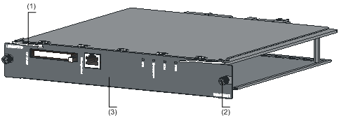
Figure 2-1 OAP card appearance
|
(1) Ejector lever |
(2) Fastening screw (captive screw) |
(3) Front panel of the OAP card |
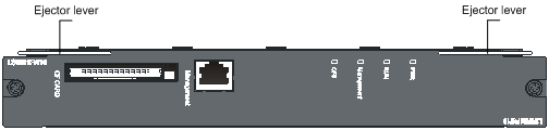
Front Panel
Appearance
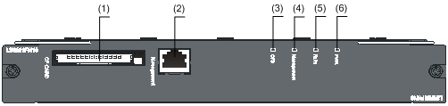
Figure 2-2 Front panel of an OAP card
|
(1) CF card interface |
(2) Management Ethernet port |
|
(3) CF card status LED (CFS) |
(4) Management Ethernet port status LED (Management) |
|
(5) System status LED (RUN) |
(6) PWR LED |
Description of the LEDs
The front panel of an OAP card provides four LEDs, namely PWR, RUN, CFS and Management. Refer to Table 2-1 for description of the LEDs.
Table 2-1 Description of the LEDs provided on the front panel of the OAP card
|
LED |
Color |
Status |
Description |
|
PWR LED |
Green/red |
Steady green |
The power system of the OAP card works normally. |
|
Steady red |
The power system of the OAP card is faulty. |
||
|
Off |
No power supply to the OAP card. Note that: If you install an OAP card to a switch working normally but the PWR LED is off, check whether the OAP card is well connected. |
||
|
System status LED (RUN) |
Green |
Slowly blinking (1.5 Hz) |
The system works normally. |
|
Fast blinking (6 Hz) |
The system is starting up/loading software. |
||
|
Off |
The system works abnormally or the system is reset. Note that: When the system is reset, the RUN LED is off; when the system is starting up, the RUN LED fast blinks; when the system completes startup and works normally, the RUN LED blinks slowly. |
||
|
CF card status LED (CFS) |
Green |
Steady green |
The CF card is normal, and no read/write operation is performed. |
|
Blinking green |
The CF card is normal, and a read/write operation is performed. |
||
|
Off |
No CF card is in the slot. |
||
|
Management Ethernet port status LED (Management) |
Green/Yellow |
Steady green |
A 1000 Mbps link is present, but no data is being received/transmitted. |
|
Blinking green |
Data is being received/transmitted at a rate of 1000 Mbps. |
||
|
Steady yellow |
A 10/100 Mbps link is present, but no data is being received/transmitted. |
||
|
Blinking yellow |
Data is being received/transmitted at a rate of 10/100 Mbps. |
||
|
Off |
No link is present. |
Management Ethernet Port
The front panel of an OAP card provides one management Ethernet port, which can work without being affected by the working status of the switching chip. Typically, a management Ethernet port is used to connect a PC for loading system programs or debugging, or connect the remote network management station for implementing remote system management. Table 2-2 describes the management Ethernet port specifications.
Table 2-2 Management Ethernet port specifications
|
Item |
Specification |
|
Connector type |
RJ-45 |
|
Transmission rate |
10/100/1000 Mbps, half/full duplex |
|
Transmission medium and maximum transmission distance |
Category-5 twisted pair cable that supports a maximum transmission distance of 100 m (328.08 ft.) |
|
Services |
Upgrade of host software and BootWare, network management. |
Hardware Specifications
Table 2-3 OAP card hardware specifications
|
Item |
Specification |
Remarks |
|
CPU |
MIPS, eight cores, 1 GHz |
— |
|
Memory |
2 GB |
Avoid replacing the memory by yourself to prevent damage to the OAP card. |
|
Number of CF card interfaces on an OAP card and the supported specifications |
l Provides one CF card interface and one 1 GB CF card when shipped. l Supports a CF card with a maximum capacity of 1 GB. |
l To replace a CF card, make sure that the new CF card can accommodate the software to be loaded. l For how to load and upgrade software version of the OAP card, refer to the related manual in the CD-ROM delivered with the OAP card. |
3 Installing an OAP Card
Installing and Removing an OAP Card
![]()
l The installation tools are not provided with the H3C series switches and OAP cards.
l This section describes the installation and removal of a firewall card on an S5800-60C-PWR switch. The installation and removal of other OAP card models are similar.
l OAP cards are hot swappable. That is, you can remove an OAP card from a switch when the switch is powered on.
Prepare the following tools before installation:
l Phillips screwdriver
l ESD-preventive wrist strap
Install an OAP card
Step1 Wear an ESD-preventive wrist strap, ensure a good skin contact and make sure that the ESD-preventive wrist strap is properly grounded.
Step2 Loosen the captive screws on the blank panel counterclockwise with a Phillips screwdriver, as shown in Figure 3-1, and remove the blank panel from the slot to be used. Keep the removed blank panel properly for future use.
Figure 3-1 Remove the blank panel
|
(1) Rotation direction of the Phillips screwdriver |
(2) Blank panel of the OAP card slot |
|
(3) Phillips screwdriver |
|
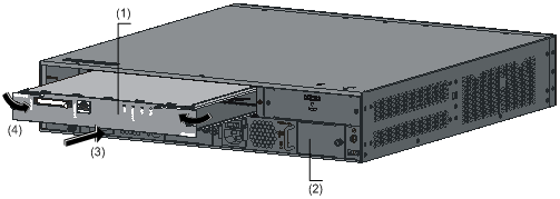
Step3 Take the OAP card out of the package. Then, you can select to insert the OAP card as shown in Figure 3-2 with the ejector levels at the bottom, or reversely insert the OAP card as shown in Figure 3-3 with the ejector levers on top. Select a proper installation mode based on the hardware structure of your switch.
![]()
The insertion and reverse insertion procedures are the same. This manual uses reverse insertion of an OAP card to an S5800-60C-PWR switch as an example.
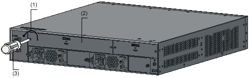
Figure 3-3 Reversely insert an OAP card
Step4 Push the OAP card slowly along the guide rails (see (3) in Figure 3-4) and then push the ejector levers inward to lock the OAP card in position (see (4) in Figure 3-4).
Figure 3-4 Install the OAP card to the switch
|
(1) OAP card |
(2) Rear panel of the switch |
|
(3) Insertion direction of the OAP card |
(4) Locking direction of the ejector levers |
![]()
When installing the OAP card, note the following:
l Do not touch the components on the surface of the OAP card.
l Do not apply excessive force while installing the OAP card. If you cannot insert the OAP card smoothly, check whether the installation mode (reverse insertion) is correct.
Step5 Fasten the captive screws on the OAP card clockwise with the Philips screwdriver until the OAP card is fixed into the chassis.
Remove an OAP card
Step1 Wear an ESD-preventive wrist strap, ensure a good skin contact and make sure that the ESD-preventive wrist strap is properly grounded.
Step2 Loosen the captive screws on the OAP card counterclockwise with the Philips screwdriver until all spring pressure is released.
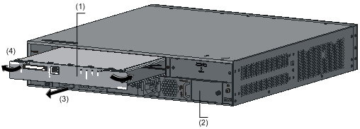
Step3 Hold each ejector lever with a hand and pull the ejector levers outward (see (4) in Figure 3-5). Then pull out the OAP card slowly along the guide rails (see (3) in Figure 3-5).
Figure 3-5 Remove the OAP card
|
(1) OAP card |
(2) Rear panel of the switch |
|
(3) Removal direction of the OAP card |
(4) Unlocking direction of the ejector levers |
![]()
The protection
panel on the OAP card surface has a yellow warning label  , indicating that this area
corresponds to the inner heat radiator. After the OAP card runs for a period of
time, this area may be very hot. So keep your hands away from the area while
removing the OAP card to avoid being hurt.
, indicating that this area
corresponds to the inner heat radiator. After the OAP card runs for a period of
time, this area may be very hot. So keep your hands away from the area while
removing the OAP card to avoid being hurt.
![]()
When removing the OAP card, note the following:
l Do not touch the components on the surface of the OAP card.
l Do not apply excessive force while removing the OAP card.
l If you do not install a new OAP card in the slot, install a blank panel to prevent dust from entering the switch and ensure normal ventilation in the switch.
Connecting the Management Ethernet Port Cable
Step1 Connect the management Ethernet port to the terminal.
l To connect the management Ethernet port of an OAP card to the Ethernet port of a PC or router, use a crossover cable.
l To connect the management Ethernet port of an OAP card to the Ethernet port of a hub or switch, use a straight-through cable.
Step2 After the OAP card is powered on, check the management Ethernet port status LED on the front panel of the OAP card. If the LED is on, a link is present; if the LED is off, no link is present, and you need to check the line.
Verifying the Installation
After the OAP card is installed, you can check the status of the LEDs on the front panel of the OAP card to verify the operation state of the OAP card. If the OAP card works abnormally, check whether the OAP card is correctly installed.
