- Table of Contents
-
- 13-Network Management and Monitoring Configuration Guide
- 00-Preface
- 01-System maintenance and debugging configuration
- 02-NQA configuration
- 03-NTP configuration
- 04-SNMP configuration
- 05-RMON configuration
- 06-Event MIB configuration
- 07-NETCONF configuration
- 08-EAA configuration
- 09-Process monitoring and maintenance configuration
- 10-Sampler configuration
- 11-Mirroring configuration
- 12-NetStream configuration
- 13-IPv6 NetStream configuration
- 14-Information center configuration
- 15-Flow log configuration
- 16-GOLD configuration
- 17-Packet capture configuration
- Related Documents
-
| Title | Size | Download |
|---|---|---|
| 17-Packet capture configuration | 431.13 KB |
Configuring the packet capture
Configuring local packet capture
Configuring remote packet capture
Configuring feature image-based packet capture
Saving captured packets to a file
Filtering packet data to display
Displaying and maintaining packet capture
Packet capture configuration examples
Remote packet capture configuration example
Filtering packet data to display configuration example
Saving captured packets to a file configuration example
Configuring the packet capture
Overview
The packet capture feature captures incoming packets that are to be forwarded in CPU. The feature displays the captured packets in real time, and allows you to save the captured packets to a .pcap file for future analysis.
Packet capture modes
You can configure packet capture for only one user at a time.
Local packet capture
Local packet capture saves the captured packets to a remote file on an FTP server, to a local file, or displays the captured packets at the CLI.
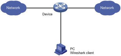
Remote packet capture
Remote packet capture displays the captured packets on a Wireshark client. Before using remote packet capture, you must install the Wireshark software on a PC and connect the PC to the device to be used to capture packets. The device sends the packet data to be displayed to the Wireshark client.
Feature image-based packet capture
|
|
NOTE: To use this mode, you must install a feature image by using the boot-loader or install command. For more information about the commands, see Fundamentals Command Reference. |
Feature image-based packet capture saves the captured packets to a local file or displays the captured packets on the terminal in a .pcap or .pcapng file.
If you uninstall the feature image, the remote and local packet capture are also uninstalled.
Filter elements
Packet capture supports capture filters and display filters. You can use expressions to match packets to capture or display.
A capture or display filter contains a keyword string or multiple keyword strings that are connected by operators.
Keywords include the following types:
· Qualifiers—Fixed keyword strings. For example, you must use the ip qualifier to specify the IPv4 protocol.
· Variables—Values supplied by users in the required format. For example, you can set an IP address to 2.2.2.2 or any other valid values.
A variable must be modified by one or multiple qualifiers. For example, to capture any packets sent from the host at 2.2.2.2, use the filter src host 2.2.2.2.
Operators include the following types:
· Logical operators—Perform logical operations, such as the AND operation.
· Arithmetic operators—Perform arithmetic operations, such as the ADD operation.
· Relational operators—Indicate the relation between keyword strings. For example, the = operator indicates equality.
This document provides basic information about these elements. For more information about capture and display filters, go to the following websites:
· http://wiki.wireshark.org/CaptureFilters.
· http://wiki.wireshark.org/DisplayFilters.
Capture filter keywords
Table 1 and Table 2 describe the qualifiers and variables for capture filters, respectively.
Table 1 Qualifiers for capture filters
|
Category |
Description |
Examples |
|
Protocol |
Matches a protocol. If you do not specify a protocol qualifier, the filter matches any supported protocols. |
· arp—Matches ARP. · icmp—Matches ICMP. · ip—Matches IPv4. · ip6—Matches IPv6. · tcp—Matches TCP. · udp—Matches UDP. |
|
Direction |
Matches packets based on its source or destination location (an IP address or port number). If you do not specify a direction qualifier, the src or dst qualifier applies. |
· src—Matches the source IP address field. · dst—Matches the destination IP address field. · src or dst—Matches the source or destination IP address field. NOTE: The src or dst qualifier applies if you do not specify a direction qualifier. For example, port 23 is equivalent to src or dst port 23. |
|
Type |
Specifies the direction type. |
· host—Matches the IP address of a host. · net—Matches an IP subnet. · port—Matches a service port number. · portrange—Matches a service port range. NOTE: The host qualifier applies if you do not specify any type qualifier. For example, src 2.2.2.2 is equivalent to src host 2.2.2.2. To specify an IPv6 subnet, you must specify the net qualifier. |
|
Others |
Any other qualifiers than the previously described qualifiers. |
· broadcast—Matches broadcast packets. · multicast—Matches multicast and broadcast packets. · less—Matches packets that are less than or equal to a specific size. · greater—Matches packets that are greater than or equal to a specific size. · len—Matches the packet length. · vlan—Matches VLAN packets. |
|
|
NOTE: The broadcast, multicast, and all protocol qualifiers cannot modify variables. |
Table 2 Variable types for capture filters
|
Variable type |
Description |
Examples |
|
|
Integer |
Represented in binary, octal, decimal, or hexadecimal notation. |
The port 23 expression matches traffic sent to or from port number 23. |
|
|
Integer range |
Represented by hyphenated integers. |
The portrange 100-200 expression matches traffic sent to or from any ports in the range of 100 to 200. |
|
|
IPv4 address |
Represented in dotted decimal notation. |
The src 1.1.1.1 expression matches traffic sent from the IPv4 host at 1.1.1.1. |
|
|
IPv6 address |
Represented in colon hexadecimal notation. |
The dst host 1::1 expression matches traffic sent to the IPv6 host at 1::1. |
|
|
IPv4 subnet |
Represented by an IPv4 network ID or an IPv4 address with a mask. |
Both of the following expressions match traffic sent to or from the IPv4 subnet 1.1.1.0/24: · src 1.1.1. · src net 1.1.1.0/24. |
|
|
IPv6 network segment |
Represented by an IPv6 address with a prefix length. |
The dst net 1::/64 expression matches traffic sent to the IPv6 network 1::/64. |
|
Capture filter operators
Capture filters support logical operators (Table 3), arithmetic operators (Table 4), and relational operators (Table 5). Logical operators can use both alphanumeric and nonalphanumeric symbols. The arithmetic and relational operators can use only nonalphanumeric symbols.
Logical operators are left associative. They group from left to right. The not operator has the highest priority. The and and or operators have the same priority.
Table 3 Logical operators for capture filters
|
Nonalphanumeric symbol |
Alphanumeric symbol |
Description |
|
! |
not |
Reverses the result of a condition. Use this operator to capture traffic that matches the opposite value of a condition. For example, to capture non-HTTP traffic, use not port 80. |
|
&& |
and |
Joins two conditions. Use this operator to capture traffic that matches both conditions. For example, to capture non-HTTP traffic that is sent to or from 1.1.1.1, use host 1.1.1.1 and not port 80. |
|
|| |
or |
Joins two conditions. Use this operator to capture traffic that matches either of the conditions. For example, to capture traffic that is sent to or from 1.1.1.1 or 2.2.2.2, use host 1.1.1.1 or host 2.2.2.2. |
Table 4 Arithmetic operators for capture filters
|
Nonalphanumeric symbol |
Description |
|
+ |
Adds two values. |
|
- |
Subtracts one value from another. |
|
* |
Multiplies one value by another. |
|
/ |
Divides one value by another. |
|
& |
Returns the result of the bitwise AND operation on two integral values in binary form. |
|
| |
Returns the result of the bitwise OR operation on two integral values in binary form. |
|
<< |
Performs the bitwise left shift operation on the operand to the left of the operator. The right-hand operand specifies the number of bits to shift. |
|
>> |
Performs the bitwise right shift operation on the operand to the left of the operator. The right-hand operand specifies the number of bits to shift. |
|
[ ] |
Specifies a byte offset relative to a protocol layer. This offset indicates the byte where the matching begins. You must enclose the offset value in the brackets and specify a protocol qualifier. For example, ip[6] matches the seventh byte of payload in IPv4 packets (the byte that is six bytes away from the beginning of the IPv4 payload). |
Table 5 Relational operators for capture filters
|
Nonalphanumeric symbol |
Description |
|
= |
Equal to. For example, ip[6]=0x1c matches an IPv4 packet if its seventh byte of payload is equal to 0x1c. |
|
!= |
Not equal to. For example, len!=60 matches a packet if its length is not equal to 60 bytes. |
|
> |
Greater than. For example, len>100 matches a packet if its length is greater than 100 bytes. |
|
< |
Less than. For example, len<100 matches a packet if its length is less than 100 bytes. |
|
>= |
Greater than or equal to. For example, len>=100 matches a packet if its length is greater than or equal to 100 bytes. |
|
<= |
Less than or equal to. For example, len<=100 matches a packet if its length is less than or equal to 100 bytes. |
Display filter keywords
Table 6 and Table 7 describe the qualifiers and variables for display filters, respectively.
Table 6 Qualifiers for display filters
|
Category |
Description |
Examples |
|
Protocol |
Matches a protocol. |
· eth—Matches Ethernet. · ftp—Matches FTP. · http—Matches HTTP. · icmp—Matches ICMP. · ip—Matches IPv4. · ipv6—Matches IPv6. · tcp—Matches TCP. · telnet—Matches Telnet. · udp—Matches UDP. |
|
Packet field |
Matches a field in packets by using a dotted string in the protocol.field[.level1-subfield]…[.leveln-subfield] format. |
· tcp.flags.syn—Matches the SYN bit in the flags field of TCP. · tcp.port—Matches the source or destination port field. |
|
|
NOTE: The protocol qualifiers cannot modify variables. |
Table 7 Variable types for display filters
|
Variable type |
Description |
|
Integer |
Represented in binary, octal, decimal, or hexadecimal notation. For example, to display IP packets that are less than or equal to 1500 bytes, use one of the following expressions: · ip.len le 1500. · ip.len le 02734. · ip.len le 0x436. |
|
Boolean |
This variable type has two values: true or false. This variable type applies if you use a packet field string alone to identify the presence of a field in a packet. · If the field is present, the match result is true. The filter displays the packet. · If the field is not present, the match result is false. The filter does not display the packet. For example, to display TCP packets that contain the SYN field, use tcp.flags.syn. |
|
MAC address (six bytes) |
Uses colons (:), dots (.), or hyphens (-) to break up the MAC address into two or four segments. For example, to display packets that contain a destination MAC address of ffff.ffff.ffff, use one of the following expressions: · eth.dst==ff:ff:ff:ff:ff:ff. · eth.dst==ff-ff-ff-ff-ff-ff. · eth.dst ==ffff.ffff.ffff. |
|
IPv4 address |
Represented in dotted decimal notation. For example: · To display IPv4 packets that are sent to or from 192.168.0.1, use ip.addr==192.168.0.1. · To display IPv4 packets that are sent to or from 129.111.0.0/16, use ip.addr==129.111.0.0/16. |
|
IPv6 address |
Represented in colon hexadecimal notation. For example: · To display IPv6 packets that are sent to or from 1::1, use ipv6.addr==1::1. · To display IPv6 packets that are sent to or from 1::/64, use ipv6.addr==1::/64. |
|
String |
Character string. For example, to display HTTP packets that contain the string HTTP/1.1 for the request version field, use http.request version=="HTTP/1.1". |
Display filter operators
Display filters support logical operators (Table 8) and relational operators (Table 9). Both operator types can use alphanumeric and nonalphanumeric symbols.
Logical operators are left associative. They group from left to right. Table 8 displays logical operators by priority, from the highest to the lowest. The and and or operators have the same priority:
Table 8 Logical operators for display filters
|
Nonalphanumeric symbol |
Alphanumeric symbol |
Description |
|
[ ] |
No alphanumeric symbol is available. |
Used with protocol qualifiers. For more information, see "The proto[…] expression." |
|
! |
not |
Displays packets that do not match the condition connected to this operator. |
|
&& |
and |
Joins two conditions. Use this operator to display traffic that matches both conditions. |
|
|| |
or |
Joins two conditions. Use this operator to display traffic that matches either of the conditions. |
Table 9 Relational operators for display filters
|
Nonalphanumeric symbol |
Alphanumeric symbol |
Description |
|
== |
eq |
Equal to. For example, ip.src==10.0.0.5 displays packets with the source IP address as 10.0.0.5. |
|
!= |
ne |
Not equal to. For example, ip.src!=10.0.0.5 displays packets whose source IP address is not 10.0.0.5. |
|
> |
gt |
Greater than. For example, frame.len>100 displays frames with a length greater than 100 bytes. |
|
< |
lt |
Less than. For example, frame.len<100 displays frames with a length less than 100 bytes. |
|
>= |
ge |
Greater than or equal to. For example, frame.len ge 0x100 displays frames with a length greater than or equal to 256 bytes. |
|
<= |
le |
Less than or equal to. For example, frame.len le 0x100 displays frames with a length less than or equal to 256 bytes. |
Building a capture filter
This section provides the most commonly used expression types for capture filters.
Logical expression
Use this type of expression to capture packets that match the result of logical operations.
Logical expressions contain keywords and logical operators. For example:
· not port 23 and not port 22—Captures packets with a port number that is not 23 or 22.
· port 23 or icmp—Captures packets with a port number 23 or ICMP packets.
In a logical expression, a qualifier can modify more than one variable connected by its nearest logical operator. For example, to capture packets sourced from IPv4 address 192.168.56.1 or IPv4 network 192.168.27, use either of the following expressions:
· src 192.168.56.1 or 192.168.27.
· src 192.168.56.1 or src 192.168.27.
The expr relop expr expression
Use this type of expression to capture packets that match the result of arithmetic operations.
This expression contains keywords, arithmetic operators (expr), and relational operators (relop). For example, len+100>=200 captures packets that are greater than or equal to 100 bytes.
The proto [ expr:size ] expression
Use this type of expression to capture packets that match the result of arithmetic operations on a number of bytes relative to a protocol layer.
This type of expression contains the following elements:
· proto—Specifies a protocol layer.
· []—Performs arithmetic operations on a number of bytes relative to the protocol layer.
· expr—Specifies the arithmetic expression.
· size—Specifies the byte offset. This offset indicates the number of bytes relative to the protocol layer. The operation is performed on the specified bytes. The offset is set to 1 byte if you do not specify an offset.
For example, ip[0]&0xf !=5 captures an IP packet if the result of ANDing the first byte with 0x0f is not 5.
To match a field, you can specify a field name for expr:size. For example, icmp[icmptype]=0x08 captures ICMP packets that contain a value of 0x08 in the Type field.
The vlan vlan_id expression
Use this type of expression to capture 802.1Q tagged VLAN traffic.
This type of expression contains the vlan vlan_id keywords and logical operators. The vlan_id variable is an integer that specifies a VLAN ID. For example, vlan 1 and ip6 captures IPv6 packets in VLAN 1.
To capture 802.1Q tagged traffic, you must use the vlan vlan_id expression prior to any other expressions. An expression matches untagged packets if it does not follow a vlan vlan_id expression. For example:
· vlan 1 and !tcp—Captures VLAN 1-tagged non-TCP packets.
· icmp and vlan 1—Captures untagged ICMP packets that are VLAN 1 tagged. This expression does not capture any packets because no packets can be both tagged and untagged.
Building a display filter
This section provides the most commonly used expression types for display filters.
Logical expression
Use this type of expression to display packets that match the result of logical operations.
Logical expressions contain keywords and logical operators. For example, ftp or icmp displays all FTP packets and ICMP packets.
Relational expression
Use this type of expression to display packets that match the result of comparison operations.
Relational expressions contain keywords and relational operators. For example, ip.len<=28 displays IP packets that contain a value of 28 or fewer bytes in the length field.
Packet field expression
Use this type of expression to display packets that contain a specific field.
Packet field expressions contain only packet field strings. For example, tcp.flags.syn displays all TCP packets that contain the SYN bit field.
The proto[…] expression
Use this type of expression to display packets that contain specific field values.
This type of expression contains the following elements:
· proto—Specifies a protocol layer or packet field.
· […]—Matches a number of bytes relative to a protocol layer or packet field. Values for the bytes to be matched must be a hexadecimal integer string. The expression in brackets can use the following formats:
? [n:m]—Matches a total of m bytes after an offset of n bytes from the beginning of the specified protocol layer or field. To match only 1 byte, you can use both [n] and [n:1] formats. For example, eth.src[0:3]==00:00:83 matches an Ethernet frame if the first three bytes of its source MAC address are 0x00, 0x00, and 0x83. The eth.src[2] == 83 expression matches an Ethernet frame if the third byte of its source MAC address is 0x83.
? [n-m]—Matches a total of (m-n+1) bytes, starting from the (n+1)th byte relative to the beginning of the specified protocol layer or packet field. For example, eth.src[1-2]==00:83 matches an Ethernet frame if the second and third bytes of its source MAC address are 0x00 and 0x83, respectively.
Configuring local packet capture
Perform this task to capture incoming packets and save the captured packets to a local file or to a remote file on an FTP server. To display the captured packets on the local device, use the packet-capture read command. To display the captured packets on the FTP server, use the Wireshark client connected to the FTP server. To stop the capture while it is capturing packets, use the packet-capture stop command.
To configure local packet capture:
|
Task |
Command |
Remarks |
|
Configure local packet capture. |
packet-capture local interface interface-type interface-number [ capture-filter capt-expression | limit-frame-size bytes | autostop filesize kilobytes | autostop duration seconds ] * write { filepath | url url [ username username [ password { cipher | simple } string ] ] } |
After this command is executed, you can still configure other commands from the CLI. The operation does not affect the packet capture. |
Configuring remote packet capture
|
Task |
Command |
Remarks |
|
Configure remote packet capture. |
packet-capture remote interface interface-type interface-number [ port port ] |
To stop the capture while it is capturing packets, use the packet-capture stop command. |
To display the captured packets, perform the following tasks:
1. Connect the Wireshark client to the device that captures packets.
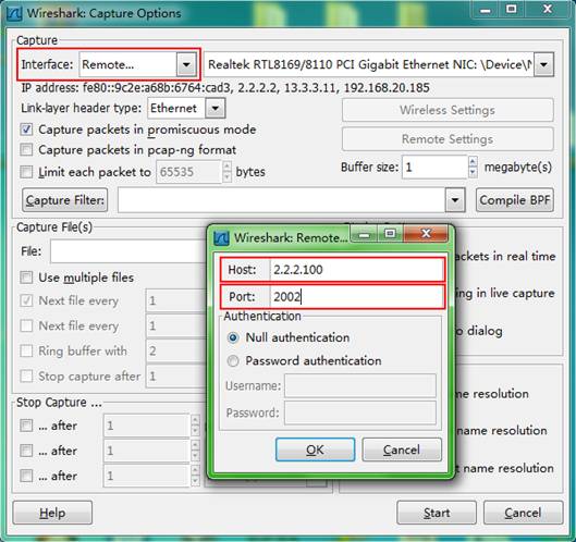
2. Start Wireshark and select Capture > Options.
3. Select Remote from the Interface list.
4. Enter the IP address of the remote interface and the RPCAP service port number on the window that appears, and click OK.
Make sure the interface IP address is reachable for the Wireshark. If you do not specify the RPCAP service port number, the default RPCAP service port 2002 is used.
5. Click Start.
Figure 1 Configuring Wireshark capture options
Configuring feature image-based packet capture
To use the packet capture feature, you must install the feature image by using the boot-loader or install command. For more information about the commands, see Fundamentals Command Reference.
Saving captured packets to a file
Perform this task to capture incoming packets on an interface and save the captured packets to a file. To display the captured packets, use the packet-capture read command. To stop the capture while it is capturing packets, press Ctrl+C. There might be a delay for the capture to stop because of heavy traffic.
To save the captured packets to a file:
|
Task |
Command |
Remarks |
|
Save the captured packets to a file. |
packet-capture interface interface-type interface-number [ capture-filter capt-expression | limit-captured-frames limit | limit-frame-size bytes | autostop filesize kilobytes | autostop duration seconds | autostop files numbers | capture-ring-buffer filesize kilobytes | capture-ring-buffer duration seconds | capture-ring-buffer files numbers ] * write filepath [ raw | { brief | verbose } ] * |
After this command is executed, you cannot configure other commands from the CLI until the capture completes capturing packets or it is stopped. |
Filtering packet data to display
To stop the capture while it is capturing packets, press Ctrl+C. There might be a delay for the capture to stop because of heavy traffic.
To filter packet data to display:
|
Task |
Command |
Remarks |
|
Filter packet data to display. |
packet-capture interface interface-type interface-number [ capture-filter capt-expression | display-filter disp-expression | limit-captured-frames limit | limit-frame-size bytes | autostop duration seconds ] * [ raw | { brief | verbose } ] * |
After this command is executed, you cannot configure other commands from the CLI until the capture completes capturing packets or it is stopped. |
Displaying and maintaining packet capture
Execute display commands in any view.
|
Command |
|
|
Display the packet capture status. |
display packet-capture status |
Packet capture configuration examples
Remote packet capture configuration example
Network requirements
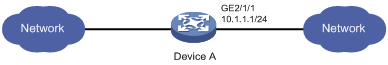
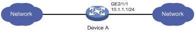
As shown in Figure 2, capture packets on GigabitEthernet 2/1/1 and use Wireshark to display the captured packets.
Configuration procedure
1. Configure remote packet capture on GigabitEthernet 2/1/1 and specify the RPCAP service port number as 2014.
<Device> packet-capture remote interface gigabitethernet 2/1/1 port 2014
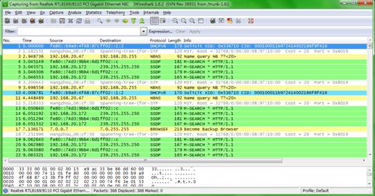
2. Display captured packets on the PC:
a. Start Wireshark and select Capture > Options.
b. Select Remote from the Interface list.
c. Enter an IP address of 10.1.1.1 and a port number of 2014, and click OK.
d. Click Start.
The captured packets are displayed on the page that appears.
Figure 3 Displaying the captured packets on the Wireshark
Filtering packet data to display configuration example
Network requirements
As shown in Figure 4, capture 11 TCP packets that are received with the source IP address 192.168.20.173 on GigabitEthernet 2/1/1.
Configuration procedure
# Capture packets on GigabitEthernet 2/1/1. Specify the capture filter expression as src 192.168.20.173 and tcp. Set the maximum number of captured packets to 11.
<RouterA> packet-capture interface gigabitethernet2/1/1 limit-captured-frames 11 capture-filter "src 192.168.20.173 and tcp"
Capturing on 'GigabitEthernet2/1/1'
1 0.000000 192.168.20.173 -> 192.168.20.175 TCP 60 55681 > telnet [ACK] Seq=
1 Ack=1 Win=16291 Len=0
2 0.206292 192.168.20.173 -> 192.168.20.175 TCP 60 55681 > telnet [ACK] Seq=
1 Ack=108 Win=16264 Len=0
3 0.407123 192.168.20.173 -> 192.168.20.175 TCP 60 55681 > telnet [ACK] Seq=
1 Ack=217 Win=16237 Len=0
4 0.607133 192.168.20.173 -> 192.168.20.175 TCP 60 55681 > telnet [ACK] Seq=
1 Ack=326 Win=16210 Len=0
5 0.807731 192.168.20.173 -> 192.168.20.175 TCP 60 55681 > telnet [ACK] Seq=
1 Ack=435 Win=16182 Len=0
6 1.007862 192.168.20.173 -> 192.168.20.175 TCP 60 55681 > telnet [ACK] Seq=
1 Ack=544 Win=16155 Len=0
7 1.208824 192.168.20.173 -> 192.168.20.175 TCP 60 55681 > telnet [ACK] Seq=
1 Ack=653 Win=16128 Len=0
8 1.409989 192.168.20.173 -> 192.168.20.175 TCP 60 55681 > telnet [ACK] Seq=
1 Ack=762 Win=16101 Len=0
9 1.609838 192.168.20.173 -> 192.168.20.175 TCP 60 55681 > telnet [ACK] Seq=
1 Ack=871 Win=16073 Len=0
10 1.810839 192.168.20.173 -> 192.168.20.175 TCP 60 55681 > telnet [ACK] Seq=
1 Ack=980 Win=16425 Len=0
11 2.011962 192.168.20.173 -> 192.168.20.175 TCP 60 55681 > telnet [ACK] Seq=
1 Ack=1089 Win=16397 Len=0
11 packets captured
Saving captured packets to a file configuration example
Network requirements
As shown in Figure 5:
· Capture 10 incoming packets on GigabitEthernet 2/1/1 and save the packets to a packet file.
· Display contents in the file.
Configuration procedure
# Capture packets on GigabitEthernet 2/1/1. Set the maximum number of captured packets to 10. Save the packets to the file flash:/a.pcap.
<DeviceA> packet-capture interface gigabitethernet2/1/1 limit-captured-frames 10 write flash:/a.pcap
Capturing on 'GigabitEthernet2/1/1'
10
# Display the contents in the packet file.
<DeviceA> packet-capture read flash:/a.pcap
1 0.000000 192.168.56.1 -> 192.168.56.2 TCP 62 6325 > telnet [SYN] Seq=0 Win
=65535 Len=0 MSS=1460 SACK_PERM=1
2 0.000061 192.168.56.1 -> 192.168.56.2 TCP 60 6325 > telnet [ACK] Seq=1 Ack
=1 Win=65535 Len=0
3 0.024370 192.168.56.1 -> 192.168.56.2 TELNET 60 Telnet Data ...
4 0.024449 192.168.56.1 -> 192.168.56.2 TELNET 78 Telnet Data ...
5 0.025766 192.168.56.1 -> 192.168.56.2 TELNET 65 Telnet Data ...
6 0.035096 192.168.56.1 -> 192.168.56.2 TELNET 60 Telnet Data ...
7 0.047317 192.168.56.1 -> 192.168.56.2 TCP 60 6325 > telnet [ACK] Seq=42 Ac
k=434 Win=65102 Len=0
8 0.050994 192.168.56.1 -> 192.168.56.2 TCP 60 6325 > telnet [ACK] Seq=42 Ac
k=436 Win=65100 Len=0
9 0.052401 192.168.56.1 -> 192.168.56.2 TCP 60 6325 > telnet [ACK] Seq=42 Ac
k=438 Win=65098 Len=0
10 0.057736 192.168.56.1 -> 192.168.56.2 TCP 60 6325 > telnet [ACK] Seq=42 Ac
k=440 Win=65096 Len=0
