- Table of Contents
-
- 03-Layer 2 - LAN Switching Configuration Examples
- 01-H3C_S7500E-XS_MAC_Address_Table_Configuration_Examples
- 02-H3C_S7500E-XS_Ethernet_Link_Aggregation_Configuration_Examples
- 03-H3C S7500E-XS_Port_Isolation_Configuration_Examples
- 04-H3C_S7500E-XS_Spanning_Tree_Configuration_Examples
- 05-H3C_S7500E-XS_VLAN_Configuration_Examples
- 06-H3C_S7500E-XS_MVRP_Configuration_Examples
- 07-H3C_S7500E-XS_QinQ_Configuration_Examples
- 08-H3C_S7500E-XS_VLAN_Mapping_Configuration_Examples
- Related Documents
-
| Title | Size | Download |
|---|---|---|
| 02-H3C_S7500E-XS_Ethernet_Link_Aggregation_Configuration_Examples | 132.99 KB |
H3C S7500E-XS Ethernet Link Aggregation Configuration Examples
|
Copyright © 2016 Hangzhou H3C Technologies Co., Ltd. All rights reserved. No part of this manual may be reproduced or transmitted in any form or by any means without prior written consent of Hangzhou H3C Technologies Co., Ltd. The information in this document is subject to change without notice. |
|
Contents
Example: Configuring Layer 2 link aggregation
Configuration restrictions and guidelines
Example: Configuring Layer 3 link aggregation
Configuration restrictions and guidelines
Introduction
This document provides Ethernet link aggregation configuration examples.
Prerequisites
The configuration examples in this document were created and verified in a lab environment, and all the devices were started with the factory default configuration. When you are working on a live network, make sure you understand the potential impact of every command on your network.
This document assumes that you have basic knowledge of Ethernet link aggregation.
Example: Configuring Layer 2 link aggregation
Network requirements
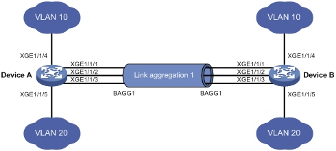
As shown in Figure 1, both Device A and Device B forward traffic from VLAN 10 and VLAN 20.
Configure link aggregation on Device A and Device B to meet the following requirements:
· VLAN 10 on Device A can communicate with VLAN 10 on Device B.
· VLAN 20 on Device A can communicate with VLAN 20 on Device B.
Requirements analysis
To enable traffic from VLAN 10 and VLAN 20 to pass through Layer 2 aggregate interface Bridge-aggregation 1, perform the following tasks:
· Configure Layer 2 aggregate interface Bridge-aggregation 1 as a trunk port.
· Assign the aggregate interface to VLAN 10 and VLAN 20.
Software version used
This configuration example was created and verified on S7500EXS-CMW710-R7178.
Configuration restrictions and guidelines
When you configure Layer 2 link aggregation, follow these restrictions and guidelines:
· When you assign a port to an aggregation group, the recommended configuration procedure is as follows:
a. Use the display this command in interface view to check the following attribute configurations of the port:
- Port isolation.
- QinQ.
- VLAN.
- VLAN mapping.
b. If any of the above configurations exist, use the undo forms of the corresponding commands to remove these configurations. This enables the port to use the default attribute configurations.
c. Assign the port to the aggregation group.
· An aggregation group can operate in static or dynamic mode. You can choose one mode as required.
¡ In a static aggregation group, the aggregation states of the member ports are not affected by the peer ports. Static link aggregation is stable.
¡ In a dynamic aggregation group, the local system and the peer system automatically maintain the aggregation states of the member ports. Dynamic link aggregation reduces the administrators' workload.
· In a static aggregation group, the Selected state of a port is not affected by whether the peer port is added to an aggregation group and is Selected. As a result, the Selected state of a port might be different from the Selected state of the peer port. When both ends support static aggregation and dynamic aggregation, H3C recommends using dynamic aggregation.
· You cannot assign a port to a Layer 2 aggregation group when MAC authentication, port security mode, or 802.1X is configured or enabled on the port.
Configuration procedures
1. Configure Device A:
# Create VLAN 10, and assign port Ten-GigabitEthernet 1/1/4 to VLAN 10.
<DeviceA> system-view
[DeviceA] vlan 10
[DeviceA-vlan10] port ten-gigabitethernet 1/1/4
[DeviceA-vlan10] quit
# Create VLAN 20, and assign port Ten-GigabitEthernet 1/1/5 to VLAN 20.
[DeviceA] vlan 20
[DeviceA-vlan20] port ten-gigabitethernet 1/1/5
[DeviceA-vlan20] quit
# Create Layer 2 aggregate interface Bridge-aggregation 1. Use one of the following methods as needed.
¡ Use the static aggregation mode to create Layer 2 aggregate interface Bridge-aggregation 1.
[DeviceA] interface bridge-aggregation 1
[DeviceA-Bridge-Aggregation1] quit
¡ Use the dynamic aggregation mode to create Layer 2 aggregate interface Bridge-aggregation 1.
[DeviceA] interface bridge-aggregation 1
[DeviceA-Bridge-Aggregation1] link-aggregation mode dynamic
[DeviceA-Bridge-Aggregation1] quit
# Assign ports Ten-GigabitEthernet 1/1/1 through Ten-GigabitEthernet 1/1/3 to aggregation group 1.
[DeviceA] interface ten-gigabitethernet 1/1/1
[DeviceA-Ten-GigabitEthernet1/1/1] port link-aggregation group 1
[DeviceA-Ten-GigabitEthernet1/1/1] quit
[DeviceA] interface ten-gigabitethernet 1/1/2
[DeviceA-Ten-GigabitEthernet1/1/2] port link-aggregation group 1
[DeviceA-Ten-GigabitEthernet1/1/2] quit
[DeviceA] interface ten-gigabitethernet 1/1/3
[DeviceA-Ten-GigabitEthernet1/1/3] port link-aggregation group 1
[DeviceA-Ten-GigabitEthernet1/1/3] quit
# Configure Layer 2 aggregate interface Bridge-aggregation 1 as a trunk port.
[DeviceA] interface bridge-aggregation 1
[DeviceA-Bridge-Aggregation1] port link-type trunk
Configuring Ten-GigabitEthernet1/1/1 done.
Configuring Ten-GigabitEthernet1/1/2 done.
Configuring Ten-GigabitEthernet1/1/3 done.
# Assign the aggregate interface to VLANs 10 and 20.
[DeviceA-Bridge-Aggregation1] port trunk permit vlan 10 20
Configuring Ten-GigabitEthernet1/1/1 done.
Configuring Ten-GigabitEthernet1/1/2 done.
Configuring Ten-GigabitEthernet1/1/3 done.
[DeviceA-Bridge-Aggregation1] quit
2. Configure Device B in the same way Device A is configured. (Details not shown.)
Verifying the configuration
# Display detailed information about the link aggregation groups on Device A.
· Link aggregation configuration information when the static aggregation mode is used:
[DeviceA] display link-aggregation verbose
Loadsharing Type: Shar -- Loadsharing, NonS -- Non-Loadsharing
Port Status: S -- Selected, U -- Unselected, I -- Individual
Flags: A -- LACP_Activity, B -- LACP_Timeout, C -- Aggregation,
D -- Synchronization, E -- Collecting, F -- Distributing,
G -- Defaulted, H -- Expired
Aggregation Interface: Bridge-Aggregation1
Aggregation Mode: Static
Loadsharing Type: Shar
Port Status Priority Oper-Key
--------------------------------------------------------------------------------
XGE1/1/1 S 32768 1
XGE1/1/2 S 32768 1
XGE1/1/3 S 32768 1
The output shows that all member ports in the local aggregation group are in the Selected state. The Selected states of the local member ports are not affected by the Selected states of the peer member ports.
· Link aggregation configuration information when the dynamic aggregation mode is used:
[DeviceA] display link-aggregation verbose
Loadsharing Type: Shar -- Loadsharing, NonS -- Non-Loadsharing
Port Status: S -- Selected, U -- Unselected, I -- Individual
Flags: A -- LACP_Activity, B -- LACP_Timeout, C -- Aggregation,
D -- Synchronization, E -- Collecting, F -- Distributing,
G -- Defaulted, H -- Expired
Aggregation Interface: Bridge-Aggregation11
Aggregation Mode: Dynamic
Loadsharing Type: Shar
System ID: 0x8000, 000f-e234-5678
Local:
Port Status Priority Oper-Key Flag
--------------------------------------------------------------------------------
XGE1/1/1 S 32768 1 {ACDEF}
XGE1/1/2 S 32768 1 {ACDEF}
XGE1/1/3 S 32768 1 {ACDEF}
Remote:
Actor Partner Priority Oper-Key SystemID Flag
--------------------------------------------------------------------------------
XGE1/1/1 14 32768 1 0x8000, 0000-fc00-7506 {ACDEF}
XGE1/1/2 15 32768 1 0x8000, 0000-fc00-7506 {ACDEF}
XGE1/1/3 16 32768 1 0x8000, 0000-fc00-7506 {ACDEF}
The output shows that the local member ports and the corresponding peer member ports are all Selected. In the dynamic link aggregation mode, each local member port and its peer member port have the same Selected state through exchanging LACPDUs. The user data traffic can be forwarded correctly.
Configuration files
· Device A:
#
vlan 10
#
interface Ten-GigabitEthernet1/1/4
port link-mode bridge
port access vlan 10
#
vlan 20
#
interface Ten-GigabitEthernet1/1/5
port link-mode bridge
port access vlan 20
¡ In the static aggregation mode:
#
interface Bridge-Aggregation1
port link-type trunk
port trunk permit vlan 10 20
¡ In the dynamic aggregation mode:
#
interface Bridge-Aggregation1
port link-type trunk
port trunk permit vlan 10 20
link-aggregation mode dynamic
#
interface Ten-GigabitEthernet1/1/1
port link-mode bridge
port link-type trunk
port trunk permit vlan 10 20
port link-aggregation group 1
#
interface Ten-GigabitEthernet1/1/2
port link-mode bridge
port link-type trunk
port trunk permit vlan 10 20
port link-aggregation group 1
#
interface Ten-GigabitEthernet1/1/3
port link-mode bridge
port link-type trunk
port trunk permit vlan 10 20
port link-aggregation group 1
#
· Device B:
The configuration file on Device B is the same as the configuration file on Device A.
Example: Configuring Layer 3 link aggregation
Network requirements
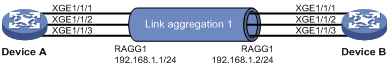
On the network as shown in Figure 2, perform the following tasks:
· Configure a Layer 3 dynamic aggregation group on both Device A and Device B.
· Configure IP addresses and subnet masks for the corresponding Layer 3 aggregate interfaces.
Software version used
This configuration example was created and verified on S7500EXS-CMW710-R7178.
Configuration restrictions and guidelines
An aggregation group can operate in static or dynamic mode. You can choose one mode as required.
· In a static aggregation group, the aggregation states of the member ports are not affected by the peer ports. Static link aggregation is stable.
· In a dynamic aggregation group, the local system and the peer system automatically maintain the aggregation states of the member ports. Dynamic link aggregation reduces the administrators' workload.
Configuration procedures
# Create Layer 3 aggregate interface Route-Aggregation 1. Use one of the following methods as needed.
¡ Use the static aggregation mode to create Layer 3 aggregate interface Route-Aggregation 1.
<DeviceA> system-view
[DeviceA] interface route-aggregation 1
¡ Use the dynamic aggregation mode to create Layer 3 aggregate interface Route-Aggregation 1.
[DeviceA] interface route-aggregation 1
[DeviceA-Route-Aggregation1] link-aggregation mode dynamic
# Configure an IP address and subnet mask for Layer 3 aggregate interface Route-Aggregation 1.
[DeviceA-Route-Aggregation1] ip address 192.168.1.1 24
[DeviceA-Route-Aggregation1] quit
# Assign ports Ten-GigabitEthernet 1/1/1 through Ten-GigabitEthernet 1/1/3 to aggregation group 1.
[DeviceA] interface range ten-gigabitethernet 1/1/1 to ten-gigabitethernet 1/1/3
[DeviceA-if-range] port link-aggregation group 1
[DeviceA-if-range] quit
2. Configure Device B in the same way Device A is configured. (Details not shown.)
Verifying the configuration
# Display detailed information about the link aggregation groups on Device A.
· Link aggregation configuration information when the static aggregation mode is used:
[DeviceA] display link-aggregation verbose
Loadsharing Type: Shar -- Loadsharing, NonS -- Non-Loadsharing
Port Status: S -- Selected, U -- Unselected
Flags: A -- LACP_Activity, B -- LACP_Timeout, C -- Aggregation,
D -- Synchronization, E -- Collecting, F -- Distributing,
G -- Defaulted, H -- Expired
Aggregate Interface: Route-Aggregation1
Aggregation Mode: Static
Loadsharing Type: Shar
Port Status Priority Oper-Key
--------------------------------------------------------------------------------
XGE1/1/1 S 32768 1
XGE1/1/2 S 32768 1
XGE1/1/3 S 32768 1
The output shows that all member ports in the local aggregation group are in Selected state. The Selected states of the local member ports are not affected by the Selected states of the peer member ports.
· Link aggregation configuration information when the dynamic aggregation mode is used:
[DeviceA] display link-aggregation verbose
Loadsharing Type: Shar -- Loadsharing, NonS -- Non-Loadsharing
Port Status: S -- Selected, U -- Unselected
Flags: A -- LACP_Activity, B -- LACP_Timeout, C -- Aggregation,
D -- Synchronization, E -- Collecting, F -- Distributing,
G -- Defaulted, H -- Expired
Aggregate Interface: Route-Aggregation1
Aggregation Mode: Dynamic
Loadsharing Type: Shar
System ID: 0x8000, 000f-e267-6c6a
Local:
Port Status Priority Oper-Key Flag
--------------------------------------------------------------------------------
XGE1/1/1 S 32768 1 {ACDEF}
XGE1/1/2 S 32768 1 {ACDEF}
XGE1/1/3 S 32768 1 {ACDEF}
Remote:
Actor Partner Priority Oper-Key SystemID Flag
--------------------------------------------------------------------------------
XGE1/1/1 1 32768 1 0x8000, 000f-e267-57ad {ACDEF}
XGE1/1/2 2 32768 1 0x8000, 000f-e267-57ad {ACDEF}
XGE1/1/3 3 32768 1 0x8000, 000f-e267-57ad {ACDEF}
The output shows that the local member ports and the corresponding peer member ports are all Selected. In the dynamic link aggregation mode, each local member port and its peer member port have the same Selected state through exchanging LACPDUs. The user data traffic can be forwarded correctly.
Configuration files
· Device A:
#
¡ In the static aggregation mode:
#
interface route-aggregation1
ip address 192.168.1.1 255.255.255.0
#
¡ In the dynamic aggregation mode:
#
interface route-aggregation1
ip address 192.168.1.1 255.255.255.0
link-aggregation mode dynamic
#
interface Ten-GigabitEthernet1/1/1
port link-mode route
port link-aggregation group 1
#
interface Ten-GigabitEthernet1/1/2
port link-mode route
port link-aggregation group 1
#
interface Ten-GigabitEthernet1/1/3
port link-mode route
port link-aggregation group 1
#
· Device B:
The configuration file on Device B is similar as the configuration file on Device A.
Related documentation
· H3C S7500E-XS Switch Series Layer 2—LAN Switching Command Reference-Release 7178
· H3C S7500E-XS Switch Series Layer 2—LAN Switching Configuration Guide-Release 7178