- Table of Contents
-
- 09-ACL and QoS Configuration Examples
- 00-S12500_ACL_Configuration_Examples
- 01-S12500_Packet_Filtering_Configuration_Examples
- 02-S12500_Priority_Mapping_and_Priority_Marking_Configuration_Examples
- 03-S12500_Traffic_Policing_Configuration_Examples
- 04-S12500_GTS_Configuration_Examples
- 05-S12500_Queue_Scheduling_Configuration_Examples
- 06-S12500_Control_Plane-Based_QoS_Policy_Configuration_Examples
- Related Documents
-
| Title | Size | Download |
|---|---|---|
| 05-S12500_Queue_Scheduling_Configuration_Examples | 88.24 KB |
Introduction
This document provides queue scheduling configuration examples.
To perform queue scheduling on a port where congestion occurs, you can configure a queue scheduling profile to modify the scheduling parameters for each queue and then apply the queue scheduling profile to the port to implement congestion management.
Prerequisites
The configuration examples in this document were created and verified in a lab environment, and all the devices were started with the factory default configuration. If you are working on a live network, make sure you understand the potential impact of every command on your network.
This document assumes that you have basic knowledge of queue scheduling.
Example: Configuring queue scheduling
Network requirements
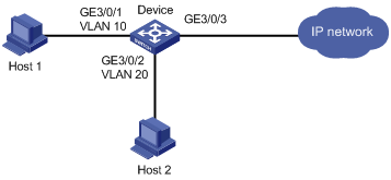
As shown in Figure 1:
· Community users Host 1 and Host 2 are connected to GigabitEthernet 3/0/1 and GigabitEthernet 3/0/2 of Device, respectively.
· Device connects to an external network through GigabitEthernet 3/0/3.
Configure queue scheduling to meet the following requirements:
|
Host |
User level |
Requirements |
|
Host 1 |
VIP user |
· Traffic must be scheduled preferentially. The traffic of Host 1 includes data traffic, voice traffic, and video traffic, with 802.1p priorities 3, 4, and 5, and the three flows are scheduled in the ratio of 1:4:4. · Host 1 has reserved services 1 and 2, with the 802.1p priorities 7 and 6, respectively. Reserved service 1 is of higher priority than reserved service 2. Make sure traffic of the reserved services is scheduled preferentially when congestion occurs. |
|
Host 2 |
Common user |
The traffic of Host 2 includes data traffic, voice traffic, and video traffic, with 802.1p priorities 0, 1, and 2, and the three flows are scheduled in the ratio of 1:2:2. |
Requirements analysis
When the priorities of various services are known, to perform differentiated processing for different users and different types of services and guarantee high-priority services are preferentially processed during congestion, you can do the following:
· Configure the priority trust mode on the incoming port.
· Adjust the priority mapping tables.
· Apply a queue scheduling profile to the outgoing port.
In this example, the 802.1p priorities of various services are known. You can configure the priority trust mode as 802.1p on the ports and use the 802.1p priorities for priority mapping. You can assign different local precedence values to different services through modifying the uncolored dot1p-lp priority mapping table. The uncolored dot1p-lp priority mapping table is used because packets in this example have not been processed by traffic policing. In this example, map 802.1p priorities 0 through 7 to local precedence values 0 through 7, respectively. Then, packets are assigned to different output queues based on their local precedence values.
In this example, the following services are in descending order of priority:
· Reserved service 1 of Host 1.
· Reserved service 2 of Host 1.
· Traffic of Host 1 (including data traffic, voice traffic, and video traffic).
· Traffic of Host 2 (including data traffic, voice traffic, and video traffic).
The data traffic, voice traffic, and video traffic of each host are scheduled in a ratio.
To meet the requirement, you can use SP + WRR queuing as follows:
· Use SP for the reserved services.
· Use WRR for the data service, voice service, and video service.
· Assign these services that will use WRR to continuously-numbered queues.
More specifically, configure SP + WRR as described in the following table:
|
Priority group |
Queues |
Weight |
|
WRR group 1 |
0, 1, and 2 |
1, 2, and 2 |
|
WRR group 2 |
3, 4, and 5 |
1, 4, and 4 |
|
SP group |
6 and 7 |
N/A |
Software version used
This configuration example was created and verified on S12500-CMW520-R1825P01.
Configuration restrictions and guidelines
When you configure queue scheduling, follow these restrictions and guidelines:
· H3C recommends not configuring queue scheduling on a card whose silkscreen contains XP32.
· To guarantee the queues scheduling effect, make sure queues assigned to the same WRR group are continuously-numbered when you configure WRR. For example, do not assign queues 2, 4, and 6 to WRR group 1, or queues 3, 5, and 7 to WRR group 2.
Configuration procedures
# Configure VLAN 10 and VLAN 20.
<Device> system-view
[Device] vlan 10
[Device-vlan10] quit
[Device] vlan 20
[Device-vlan20] quit
# Configure the uncolored dot1p-lp priority mapping table (which takes effect on uncolored packets) to map 802.1p priority 0 to local precedence (queue) 0, 1 to 1, and so on.
[Device] qos map-table inbound dot1p-lp
[Device-maptbl-in-dot1p-lp] import 0 export 0
[Device-maptbl-in-dot1p-lp] import 1 export 1
[Device-maptbl-in-dot1p-lp] import 2 export 2
[Device-maptbl-in-dot1p-lp] import 3 export 3
[Device-maptbl-in-dot1p-lp] import 4 export 4
[Device-maptbl-in-dot1p-lp] import 5 export 5
[Device-maptbl-in-dot1p-lp] import 6 export 6
[Device-maptbl-in-dot1p-lp] import 7 export 7
[Device-maptbl-in-dot1p-lp] quit
# Create a queue scheduling profile named Queue.
[Device] qos qmprofile Queue
# Assign queues 0, 1, and 2 to WRR group 1, with the weights of 1, 2, and 2.
[Device-qmprofile-Queue] queue 0 wrr group 1 weight 1
[Device-qmprofile-Queue] queue 1 wrr group 1 weight 2
[Device-qmprofile-Queue] queue 2 wrr group 1 weight 2
# Assign queues 3, 4, and 5 to WRR group 2, with the weights of 1, 4, and 4.
[Device-qmprofile-Queue] queue 3 wrr group 2 weight 1
[Device-qmprofile-Queue] queue 4 wrr group 2 weight 4
[Device-qmprofile-Queue] queue 5 wrr group 2 weight 4
# Assign queues 6 and 7 to the SP group.
[Device-qmprofile-Queue] queue 6 sp
[Device-qmprofile-Queue] queue 7 sp
[Device-qmprofile-Queue] quit
# Configure GigabitEthernet 3/0/1 and GigabitEthernet 3/0/2 to trust the 802.1p priorities of incoming packets.
[Device] interface GigabitEthernet 3/0/1
[Device-GigabitEthernet3/0/1] undo shutdown
[Device-GigabitEthernet3/0/1] port link-type trunk
[Device-GigabitEthernet3/0/1] port trunk permit vlan 10
[Device-GigabitEthernet3/0/1] qos trust dot1p
[Device-GigabitEthernet3/0/1] quit
[Device] interface GigabitEthernet 3/0/2
[Device-GigabitEthernet3/0/2] undo shutdown
[Device-GigabitEthernet3/0/2] port link-type trunk
[Device-GigabitEthernet3/0/2] port trunk permit vlan 20
[Device-GigabitEthernet3/0/2] qos trust dot1p
[Device-GigabitEthernet3/0/2] quit
# Apply queue scheduling profile Queue to GigabitEthernet 3/0/3.
[Device] interface GigabitEthernet 3/0/3
[Device-GigabitEthernet3/0/3] undo shutdown
[Device-GigabitEthernet3/0/3] port link-type trunk
[Device-GigabitEthernet3/0/3] port trunk permit vlan 10 20
[Device-GigabitEthernet3/0/3] qos apply qmprofile Queue
Verifying the configuration
GigabitEthernet 3/0/1 receives VLAN 10 tagged broadcast traffic with the 802.1p priorities 3 through 7 at the rate of 100 Mbps, respectively.
GigabitEthernet 3/0/2 receives VLAN 20 tagged broadcast traffic with the 802.1p priorities 0 through 2 at the rate of 100 Mbps, respectively.
· When the rate limit on GigabitEthernet 3/0/3 is set to 80 Mbps, only traffic with 802.1p priority 7 can be forwarded.
· When the rate limit on GigabitEthernet 3/0/3 is set to 150 Mbps:
¡ All traffic with 802.1p priority 7 is forwarded.
¡ Part of traffic with 802.1p priority 6 is forwarded.
¡ The other traffic is not forwarded.
· When the rate limit on GigabitEthernet 3/0/3 is set to 300 Mbps:
¡ All traffic with 802.1p priorities 6 and 7 is forwarded.
¡ Traffic with 802.1p priorities 3, 4, and 5 is forwarded in the ratio of 1:4:4.
· When the rate limit on GigabitEthernet 3/0/3 is set to 600 Mbps:
¡ All traffic with 802.1p priorities 3 through 7 is forwarded.
¡ Traffic with 802.1p priorities 0, 1, and 2 is forwarded in the ratio of 1:2:2.
Configuration files
#
vlan 1
#
vlan 10
#
vlan 20
#
qos map-table inbound dot1p-lp
import 0 export 0
import 1 export 1
import 2 export 2
#
qos qmprofile Queue
queue 0 wrr group 1 weight 1
queue 1 wrr group 1 weight 2
queue 2 wrr group 1 weight 2
queue 3 wrr group 2 weight 1
queue 4 wrr group 2 weight 4
queue 5 wrr group 2 weight 4
#
interface GigabitEthernet3/0/1
port link-mode bridge
port link-type trunk
port trunk permit vlan 1 10
qos trust dot1p
#
interface GigabitEthernet3/0/2
port link-mode bridge
port link-type trunk
port trunk permit vlan 1 20
qos trust dot1p
#
interface GigabitEthernet3/0/3
port link-mode bridge
port link-type trunk
port trunk permit vlan 1 10 20
qos apply qmprofile Queue
#
Related documentation
· H3C S12500 Routing Switch Series ACL and QoS Configuration Guide
· H3C S12500 Routing Switch Series ACL and QoS Command Reference