- Table of Contents
-
- 09-ACL and QoS Configuration Examples
- 00-S12500_ACL_Configuration_Examples
- 01-S12500_Packet_Filtering_Configuration_Examples
- 02-S12500_Priority_Mapping_and_Priority_Marking_Configuration_Examples
- 03-S12500_Traffic_Policing_Configuration_Examples
- 04-S12500_GTS_Configuration_Examples
- 05-S12500_Queue_Scheduling_Configuration_Examples
- 06-S12500_Control_Plane-Based_QoS_Policy_Configuration_Examples
- Related Documents
-
| Title | Size | Download |
|---|---|---|
| 04-S12500_GTS_Configuration_Examples | 100.54 KB |
Introduction
This document provides examples for configuring GTS.
Generic traffic shaping (GTS) provides measures to adjust the rate of outgoing traffic proactively. GTS is typically used to adapt the local traffic output rate to the downstream traffic policing specifications.
The switch supports port-based GTS and queue-based GTS. Port-based GTS regulates all packets on a port, and queue-based GTS regulates only packets of a specific queue.
Prerequisites
The configuration examples in this document were created and verified in a lab environment, and all the devices were started with the factory default configuration. When you are working on a live network, make sure you understand the potential impact of every command on your network.
This document assumes that you have basic knowledge of GTS.
Example: Configuring port-based GTS
Network requirements
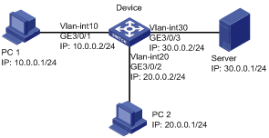
As shown in Figure 1, the server has a limited processing capacity. Configure GTS on GigabitEthernet 3/0/3 of the device to shape its outgoing traffic to the server, setting the CIR to 1000 kbps and CBS to 20000 bytes.
Software version used
This configuration example was created and verified on S12500-CMW520-R1825P01.
Configuration procedures
# Configure VLANs and IP addresses for the interfaces of the device. (Details not shown.)
# Configure GTS on GigabitEthernet 3/0/3, the interface connecting the device to the server.
[Device] interface GigabitEthernet 3/0/3
[Device-GigabitEthernet3/0/3] undo shutdown
[Device-GigabitEthernet3/0/3] qos gts any cir 1000 cbs 20000
[Device-GigabitEthernet3/0/3] quit
Verifying the configuration
# Display port-based GTS configuration on GigabitEthernet 3/0/3.
[Device]display qos gts interface GigabitEthernet 3/0/3
Interface : GigabitEthernet 3/0/3
Rule(s): If-match any
CIR 1000 (kbps), CBS 20000 (byte)
Configuration files
#
vlan 10
#
vlan 20
#
vlan 30
#
interface Vlan-interface10
ip address 10.0.0.2 255.255.255.0
#
interface Vlan-interface20
ip address 20.0.0.2 255.255.255.0
#
interface Vlan-interface30
ip address 30.0.0.2 255.255.255.0
#
interface GigabitEthernet3/0/1
port link-mode bridge
port access vlan 10
#
interface GigabitEthernet3/0/2
port link-mode bridge
port access vlan 20
#
interface GigabitEthernet3/0/3
port link-mode bridge
port access vlan 30
qos gts any cir 1000 cbs 20000
#
Example: Configuring queue-based GTS
Network requirements
As shown in Figure 2, the IP packets in two flows have DSCP values 0 and 8, respectively. Each flow enters the device at the rate of 100 Mbps, and the two flows leave the device at the same port.
Assign the two flows to different queues, and perform queue-based GTS for the two flows:
· Set the CIR to 3 Mbps and CBS to 30000 bytes for the flow with DSCP value 0.
· Set the CIR to 6 Mbps and CBS to 60000 bytes for the flow with DSCP value 8.
Requirements analysis
In this configuration example, the DSCP values are known. You can configure the priority trust mode of the interface as dscp for priority mapping and then use priority mapping tables to determine the output queues. Table 1 shows the default dscp-lp mapping. DSCP values 0 and 7 are mapped to different local precedence values (different output queues). Therefore, the default dscp-lp mapping can be used. According to the default dscp-lp mapping, the device maps packets with DSCP value 0 and DSCP value 7 to different output queues (queues 0 and 1).
Table 1 Default dscp-lp mapping
|
DSCP |
Local precedence (lp) |
|
0 to 7 |
0 |
|
8 to 15 |
1 |
|
16 to 23 |
2 |
|
24 to 31 |
3 |
|
32 to 39 |
4 |
|
40 to 47 |
5 |
|
48 to 55 |
6 |
|
56 to 63 |
7 |
Software version used
This configuration example was created and verified on S12500-CMW520-R1825P01.
Configuration procedures
# Configure VLANs and IP addresses for the interfaces of the device. (Details not shown.)
# Configure the trusted packet priority type as dscp on GigabitEthernet 3/0/1 and GigabitEthernet 3/0/2.
[Device] interface GigabitEthernet 3/0/1
[Device-GigabitEthernet3/0/1] undo shutdown
[Device-GigabitEthernet3/0/1] qos trust dscp
[Device-GigabitEthernet3/0/1] quit
[Device] interface GigabitEthernet 3/0/2
[Device-GigabitEthernet3/0/2] undo shutdown
[Device-GigabitEthernet3/0/2] qos trust dscp
[Device-GigabitEthernet3/0/2] quit
# Configure queue-based GTS for queue 0 and queue 1.
[Device] interface GigabitEthernet 3/0/3
[Device-GigabitEthernet3/0/3] undo shutdown
[Device-GigabitEthernet3/0/3] qos gts queue 0 cir 3000 cbs 30000
[Device-GigabitEthernet3/0/3] qos gts queue 1 cir 6000 cbs 60000
[Device-GigabitEthernet3/0/3] quit
Verifying the configuration
# Display queue-based GTS configuration on GigabitEthernet 3/0/3.
[Device]display qos gts interface GigabitEthernet 3/0/3
Interface : GigabitEthernet3/0/3
Rule(s): If-match queue 0
CIR 3000 (kbps), CBS 30000 (byte)
Rule(s): If-match queue 1
CIR 6000 (kbps), CBS 60000 (byte)
Configuration files
#
vlan 10
#
vlan 20
#
vlan 30
#
interface Vlan-interface10
ip address 10.0.0.2 255.255.255.0
#
interface Vlan-interface20
ip address 20.0.0.2 255.255.255.0
#
interface Vlan-interface30
ip address 30.0.0.2 255.255.255.0
#
interface GigabitEthernet3/0/1
port link-mode bridge
port access vlan 10
qos trust dscp
#
interface GigabitEthernet3/0/2
port link-mode bridge
port access vlan 20
qos trust dscp
#
interface GigabitEthernet3/0/3
port link-mode bridge
port access vlan 30
qos gts queue 0 cir 3000 cbs 30000
qos gts queue 1 cir 6000 cbs 60000
#
Related documentation
· H3C S12500 Routing Switch Series ACL and QoS Configuration Guide
· H3C S12500 Routing Switch Series ACL and QoS Command Reference