- Table of Contents
-
- 09-ACL and QoS Configuration Examples
- 00-S12500_ACL_Configuration_Examples
- 01-S12500_Packet_Filtering_Configuration_Examples
- 02-S12500_Priority_Mapping_and_Priority_Marking_Configuration_Examples
- 03-S12500_Traffic_Policing_Configuration_Examples
- 04-S12500_GTS_Configuration_Examples
- 05-S12500_Queue_Scheduling_Configuration_Examples
- 06-S12500_Control_Plane-Based_QoS_Policy_Configuration_Examples
- Related Documents
-
| Title | Size | Download |
|---|---|---|
| 02-S12500_Priority_Mapping_and_Priority_Marking_Configuration_Examples | 117.85 KB |
Contents
General configuration restrictions and guidelines
Example: Configuring priority mapping
Configuration restrictions and guidelines
Example: Configuring priority marking
Configuration restrictions and guidelines
Introduction
This document provides examples for configuring priority mapping and priority marking.
Priority mapping assigns a set of QoS priority parameters to an incoming packet by looking up the incoming port priority (default) or the trusted packet priority in the priority mapping tables.
Priority marking sets new priority values for the packets of a class.
Prerequisites
The configuration examples in this document were created and verified in a lab environment, and all the devices were started with the factory default configuration. When you are working on a live network, make sure you understand the potential impact of every command on your network.
This document assumes that you have basic knowledge of priority mapping and priority marking.
General configuration restrictions and guidelines
The dscp/exp/dot1p/lp/dp marking action conflicts with the filter deny, redirect cpu, and primap pre-defined color actions.
Example: Configuring priority mapping
Network requirements
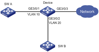
As shown in Figure 1:
· SW A is in VLAN 10. Layer 2 traffic, IP traffic, and MPLS traffic that SW A sends to the device have 802.1p priority 0, DSCP 0, and MPLS EXP 0, respectively.
· SW B is in VLAN 20. Layer 2 traffic, IP traffic, and MPLS traffic that SW B sends to the device have 802.1p priority 1, DSCP 1, and MPLS EXP 1, respectively.
Configure priority mapping on the device to meet the following requirements:
· The device forwards the traffic of SW B only after the device forwards all traffic of SW A.
· Layer 2 traffic, IP traffic, and MPLS traffic are in descending order of priority on the device.
|
|
NOTE: Layer 2 traffic in this example refers to VLAN-tagged Layer 2 packets without IP and MPLS headers. |
Requirements analysis
By default, an interface uses SP queuing, and queues 0 through 7 are in ascending order of priority. In this example, traffic policing is not configured, so packets are not colored. To adjust the priority order for these Layer 2, IP, and MPLS traffic flows on the device, change uncolored priority mapping tables and configure the priority trust mode as auto.
Software version used
This configuration example was created and verified on S12500-CMW520-R1825P01.
Configuration restrictions and guidelines
If both priority mapping and priority marking are configured for a traffic class, the priority marking action takes effect.
Configuration procedures
# Create VLAN 10 and VLAN 20.
<Device> system-view
[Device] vlan 10
[Device-vlan10] port GigabitEthernet 3/0/1
[Device-vlan10] quit
[Device] vlan 20
[Device-vlan10] port GigabitEthernet 3/0/2
[Device-vlan20] quit
# Enter the view of the uncolored dot1p-lp priority mapping table, which take effect on only uncolored packets.
[Device] qos map-table inbound dot1p-lp
# Map 802.1p priorities 0 and 1 to local precedence values 6 and 3, respectively.
[Device-maptbl-in-dot1p-lp] import 0 export 6
[Device-maptbl-in-dot1p-lp] import 1 export 3
[Device-maptbl-in-dot1p-lp] quit
# Enter the view of the uncolored dscp-lp priority mapping table, which take effect on only uncolored packets.
[Device] qos map-table inbound dscp-lp
# Map DSCP values 0 and 1 to local precedence values 5 and 2, respectively.
[Device-maptbl-in-dscp-lp] import 0 export 5
[Device-maptbl-in-dscp-lp] import 1 export 2
[Device-maptbl-in-dscp-lp] quit
# Enter the view of the uncolored exp-lp priority mapping table, which take effect on only uncolored packets.
[Device] qos map-table inbound exp-lp
# Map EXP values 0 and 1 to local precedence values 4 and 1, respectively.
[Device-maptbl-in-exp-lp] import 0 export 4
[Device-maptbl-in-exp-lp] import 1 export 1
[Device-maptbl-in-exp-lp] quit
# Configure the priority trust mode of GigabitEthernet 3/0/1 and GigabitEthernet 3/0/2 as auto.
[Device] interface GigabitEthernet 3/0/1
[Device-GigabitEthernet3/0/1] undo shutdown
[Device-GigabitEthernet3/0/1] qos trust auto
[Device-GigabitEthernet3/0/1] quit
[Device] interface GigabitEthernet 3/0/2
[Device-GigabitEthernet3/0/2] undo shutdown
[Device-GigabitEthernet3/0/2] qos trust auto
[Device-GigabitEthernet3/0/2] quit
Verifying the configuration
# Send the following types of traffic to GigabitEthernet 3/0/1, each at a rate of 100 Mbps:
· VLAN-tagged Layer 2 broadcast traffic (with source MAC address 0-0-1 and 802.1p priority 0).
· IP traffic (with source MAC address 0-0-1 and DSCP value 0).
· MPLS traffic (with source MAC address 0-0-1 and EXP value 0).
# Send the following types of traffic to GigabitEthernet 3/0/2, each at a rate of 100 Mbps:
· VLAN-tagged Layer 2 broadcast traffic (with source MAC address 0-0-2 and 802.1p priority 1).
· IP traffic (with source MAC address 0-0-2 and DSCP value 1).
· MPLS traffic (with source MAC address 0-0-2 and EXP value 1).
The following table shows the forwarding behaviors by GigabitEthernet 3/0/3 for different rate limit values:
|
Rate limit (in Mbps) on GigabitEthernet 3/0/3 |
Layer 2 traffic received on GigabitEthernet 3/0/3 |
IP traffic received on GigabitEthernet 3/0/3 |
MPLS traffic received on GigabitEthernet 3/0/3 |
|||
|
With source MAC 0-0-1 |
With source MAC 0-0-2 |
With source MAC 0-0-1 |
With source MAC 0-0-2 |
With source MAC 0-0-1 |
With source MAC 0-0-2 |
|
|
60 |
Part |
None |
None |
None |
None |
None |
|
160 |
All |
None |
Part |
None |
None |
None |
|
260 |
All |
None |
All |
None |
Part |
None |
|
360 |
All |
Part |
All |
None |
All |
None |
|
460 |
All |
All |
All |
Part |
All |
None |
|
560 |
All |
All |
All |
All |
All |
Part |
|
|
NOTE: · "None" means no traffic is forwarded. · "Part" means some of the traffic is forwarded. · "All" means all the traffic is forwarded. |
Configuration files
#
vlan 10
#
vlan 20
#
qos map-table inbound dot1p-lp
import 0 export 6
import 1 export 3
qos map-table inbound dscp-lp
import 0 export 5
import 1 export 2
qos map-table inbound exp-lp
import 0 export 4
#
interface GigabitEthernet3/0/1
port link-mode bridge
port access vlan 10
qos trust auto
#
interface GigabitEthernet3/0/2
port link-mode bridge
port access vlan 20
qos trust auto
#
Example: Configuring priority marking
Network requirements
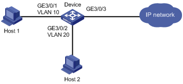
As shown in Figure 2:
· Host 1 is a VIP user in VLAN 10, and its MAC address is 0-0-1.
· Host 2 is a common user in VLAN 20, and its MAC address is 0-0-2.
Configure priority marking to make sure the traffic of Host 2 is forwarded only after all traffic of Host 1 is forwarded on GigabitEthernet 3/0/3.
Requirements analysis
By default, an interface uses SP queuing, and queues 0 through 7 are in ascending order of priority.
To preferentially transmit packets of Host 1:
1. Configure traffic classes to match packets with different source MAC addresses.
2. Configure priority marking actions to assign a higher priority to packets of Host 1 than packets of Host 2.
Software version used
This configuration example was created and verified on S12500-CMW520-R1825P01.
Configuration restrictions and guidelines
If both priority mapping and priority marking are configured for a traffic class, the priority marking action takes effect.
Configuration procedures
# Create VLAN 10 and VLAN 20.
<Device> system-view
[Device] vlan 10
[Device-vlan10] port GigabitEthernet 3/0/1
[Device-vlan10] quit
[Device] vlan 20
[Device-vlan10] port GigabitEthernet 3/0/2
[Device-vlan20] quit
# Configure a QoS policy named q1 to mark traffic sourced from MAC address 0-0-1 with local precedence 7.
[Device] traffic classifier c1
[Device-classifier-c1] if-match source-mac 0-0-1
[Device-classifier-c1] quit
[Device] traffic behavior b1
[Device-behavior-b1] remark local-precedence 7
[Device-behavior-b1] quit
[Device] qos policy q1
[Device-qospolicy-q1] classifier c1 behavior b1
[Device-qospolicy-q1] quit
# Configure a QoS policy named q2 to mark traffic sourced from MAC address 0-0-2 with local precedence 4.
[Device] traffic classifier c2
[Device-classifier-c2] if-match source-mac 0-0-2
[Device-classifier-c2] quit
[Device] traffic behavior b2
[Device-behavior-b2] remark local-precedence 4
[Device-behavior-b2] quit
[Device] qos policy q2
[Device-qospolicy-q2] classifier c2 behavior b2
[Device-qospolicy-q2] quit
# Apply the QoS policy q1 to the packets received on GigabitEthernet 3/0/1.
[Device] interface GigabitEthernet 3/0/1
[Device-GigabitEthernet3/0/1] undo shutdown
[Device-GigabitEthernet3/0/1] qos apply policy q1 inbound
[Device-GigabitEthernet3/0/1] quit
# Apply the QoS policy q2 to the packets received on GigabitEthernet 3/0/2.
[Device] interface GigabitEthernet 3/0/2
[Device-GigabitEthernet3/0/2] undo shutdown
[Device-GigabitEthernet3/0/2] qos apply policy q2 inbound
[Device-GigabitEthernet3/0/2] quit
Verifying the configuration
Send Layer 2 broadcast traffic with source MAC address 0-0-1 to GigabitEthernet 3/0/1 at a rate of 100 Mbps. Send Layer 2 broadcast traffic with source MAC address 0-0-2 to GigabitEthernet 3/0/2 at a rate of 100 Mbps.
Depending on the rate limit on GigabitEthernet 3/0/3, the following occurs:
· When the rate limit on GigabitEthernet 3/0/3 is set to 60 Mbps, GigabitEthernet 3/0/3 can forward only the Layer 2 traffic with source MAC address 0-0-1.
· When the rate limit on GigabitEthernet 3/0/3 is set to 160 Mbps, GigabitEthernet 3/0/3 can forward Layer 2 traffic with source MAC address 0-0-1 and Layer 2 traffic with source MAC address 0-0-2, and no Layer 2 packets with source MAC address 0-0-1 are lost.
Configuration files
#
vlan 10
#
vlan 20
#
traffic classifier c2 operator and
if-match source-mac 0000-0000-0002
traffic classifier c1 operator and
if-match source-mac 0000-0000-0001
#
traffic behavior b2
remark local-precedence 4
traffic behavior b1
remark local-precedence 7
#
qos policy q2
classifier c2 behavior b2
qos policy q1
classifier c1 behavior b1
#
interface GigabitEthernet3/0/1
port link-mode bridge
port access vlan 10
qos apply policy q1 inbound
#
interface GigabitEthernet3/0/2
port link-mode bridge
port access vlan 20
qos apply policy q1 inbound
#
Related documentation
· H3C S12500 Routing Switch Series ACL and QoS Configuration Guide
· H3C S12500 Routing Switch Series ACL and QoS Command Reference