- Table of Contents
-
- 08-IP Multicast Configuration Guide
- 00-Preface
- 01-Multicast Overview
- 02-IGMP Snooping Configuration
- 03-PIM Snooping Configuration
- 04-Multicast VLAN Configuration
- 05-Multicast Routing and Forwarding Configuration
- 06-IGMP Configuration
- 07-PIM Configuration
- 08-MSDP Configuration
- 09-MBGP Configuration
- 10-Multicast VPN Configuration
- 11-MLD Snooping Configuration
- 12-IPv6 PIM Snooping Configuration
- 13-IPv6 Multicast VLAN Configuration
- 14-IPv6 Multicast Routing and Forwarding Configuration
- 15-MLD Configuration
- 16-IPv6 PIM Configuration
- 17-IPv6 MBGP Configuration
- Related Documents
-
| Title | Size | Download |
|---|---|---|
| 10-Multicast VPN Configuration | 613.86 KB |
Multicast VPN configuration task list
Enabling IP multicast routing in a VPN instance
Configuring a share-group and an MTI binding
Configuring MDT switchover parameters
Enabling switch-group reuse logging
Configuring BGP MDT peers or peer groups
Configuring a BGP MDT route reflector
Displaying and maintaining multicast VPN
Multicast VPN configuration examples
Single-AS MD VPN configuration
A share-MDT cannot be established
Multicast VPN overview
|
|
NOTE: The term router in this document refers to both routers and Layer 3 switches. |
Multicast VPN is a technique that implements multicast delivery in virtual private networks (VPNs).
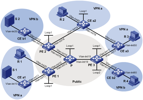
Figure 1 Typical VPN networking diagram
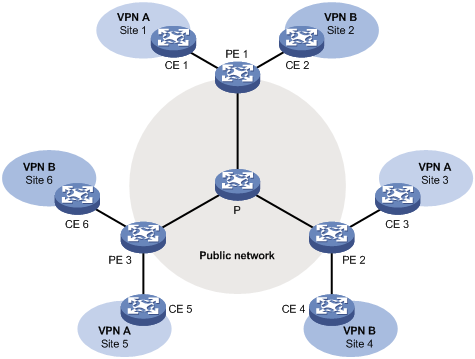
A VPN is comprised of multiple sites and the public network provided by the network provider. The sites communicate through the public network. As shown in Figure 1, VPN A comprises Site 1, Site 3 and Site 5, and VPN B comprises Site 2, Site 4 and Site 6. A VPN involves the following types of devices:
· Provider (P) device—Core device in the public network. A P device does not directly connect to CE devices.
· Provider edge (PE) device—Edge device in the public network. A PE device directly connects to one or more customer edge (CE) devices, and processes VPN routing.
· CE device—Edge device on a customer network. A CE device can be a router, a switch, or a host, that implements route distribution on the customer network.
As shown in Figure 1, the network that runs multicast VPN carries independent multicast services for the public network, VPN A, and VPN B. A PE multicast device at the edge of the public network supports multiple VPN instances, and operates as multiple independent multicast devices. Each VPN forms a plane, and all these planes are isolated from one another, as shown in Figure 2. For example, Figure 1 shows that PE1 supports the public network, VPN A, and VPN B. You can regard these instances as independent virtual devices, which are PE 1’, PE 1”, and PE 1’”. Each virtual device works on a plane as shown in Figure 2.
Figure 2 Multicast in multiple VPN instances
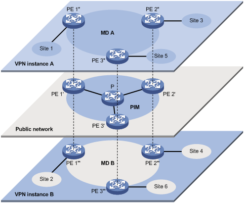
With multicast VPN, when a multicast source in VPN A sends a multicast stream to a multicast group, of all possible receivers on the network for that group, only those that belong to VPN A, namely, in Site 1, Site 3 or Site 5, can receive the multicast stream. The stream is multicast in these sites and in the public network.
The prerequisites for implementing multicast VPN are as follows:
1. Within each site, multicast for a single VPN is supported.
2. In the public network, multicast for the public network is supported.
3. The PE devices support multiple VPN instances as follows:
¡ The PE devices connect with different sites through VPNs and support multicast for each single VPN.
¡ The PE devices connect with the public network and support multicast for the public network.
¡ The PE devices support information exchange and data conversion between the public network and VPNs.
The most significant advantage of MD-VPN is that it requires only the PE devices to support multiple VPN instances. Multicast VPN can be implemented without the need of upgrading any CE devices or P devices, and without the need of changing the original PIM configuration of the CE devices or the P devices. In other words, the MD-VPN solution is transparent to the CE devices and the P devices.
MD-VPN overview
|
|
NOTE: For more information about the concepts of Protocol Independent Multicast (PIM), bootstrap router (BSR), candidate-BSR (C-BSR), rendezvous point (RP), designated forwarder (DF), candidate-RP (C-RP), shortest path tree (SPT) and rendezvous point tree (RPT), see the chapter “Configuring PIM.” |
Basic concepts in MD-VPN
The basic concepts involved in MD-VPN are described in Table 1.
Table 1 Basic concepts in MD-VPN
|
Concept |
Description |
|
Multicast domain (MD) |
An MD is a set of VPN instances running on PE devices that can send multicast traffic to each other. Each MD uniquely corresponds to the same set of VPN instances. |
|
Multicast distribution tree (MDT) |
An MDT is a multicast distribution tree between all PE devices in the same VPN. MDT types include share-MDT and switch-MDT. |
|
Multicast tunnel (MT) |
An MT is a tunnel that interconnects all PEs in an MD for delivering VPN traffic within the MD. |
|
Multicast tunnel interface (MTI) |
An MTI is the entrance to or exit of an MT, equivalent to an entrance to or exit of an MD. PE devices use the MTI to access the MD. An MTI handles only multicast packets but not unicast packets. An MTI is automatically created with the configuration of a share-group and MTI binding for a VPN instance. |
|
Share-group |
In the public network, each MD is assigned an independent multicast address, called share-group. A share-group is the unique identifier of an MD in the public network. It helps build a share-MDT corresponding to the MD in the public network. |
|
Share-multicast distribution tree (Share-MDT) |
A share-MDT is an MDT that uses a share-group as its group address. In a VPN, the share-MDT is uniquely identified by the share-group. A share-MDT is automatically created after configuration and will always exist in the public network, regardless of the presence of any actual multicast services in the public network or the VPN. |
|
Switch-multicast distribution tree (Switch-MDT) |
A switch-MDT is an MDT that uses a switch-group as it group address. At MDT switchover, PE devices with receivers downstream join a switch-group, forming a switch-MDT, along which the ingress PE forwards the encapsulated VPN multicast traffic over the public network. |
|
Switch-group |
When the multicast traffic of a VPN reaches or exceeds a threshold, the ingress PE device assigns it an independent multicast address called switch-group, and notifies the other PE devices that they should use that address to forward the multicast traffic for that VPN. This initiates a switchover to the switch-MDT. |
|
Switch-group-pool |
The switch-group-pool is a range of multicast addresses. At MDT switchover, an address (namely, switch-group address) is chosen from the switch-group-pool. The multicast packets for the VPN that enter the public network at the PE device will be encapsulated using that address. The switch-group-pool of a VPN must not overlap that of another VPN, and must not contain the share-group of another VPN. |
Introduction to MD-VPN
Main points in the implementation of MD-VPN are as follows:
1. The public network of the service provider supports multicast. The PE devices must support the public network and multiple VPN instances. Each instance runs PIM independently. VPN multicast traffic between the PE devices and the CE devices is transmitted on a per-VPN-instance basis, but the public network multicast traffic between the PE devices and the P devices is transmitted through the public network.
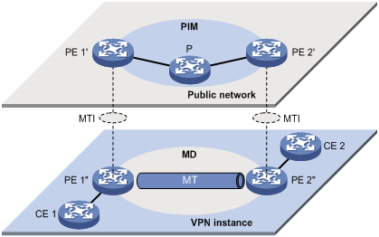
2. Logically, an MD defines the transmission range of the multicast traffic of a specific VPN over the public network. Physically, an MD identifies all the PE devices that support that VPN in the public network. Different VPN instances correspond to different MDs. As shown in Figure 3, the ellipse area in the center of each VPN instance plane represents an MD, which serves that particular VPN. All the VPN multicast traffic in that VPN is transmitted within that MD.
3. Inside an MD, all the private traffic is transmitted through the MT. The process of multicast traffic transmission through an MT is as follows. The local PE device encapsulates the VPN data into a public network packet, which is then forwarded in the public network. The remote PE device de-encapsulates the packet to turn it back into a private packet.
4. The local PE device sends out VPN data through the MTI, and the remote PE devices receive the private data through the MTI. As shown in Figure 3, you can think of an MD as a private data transmission pool, and you can think of an MTI as an entrance or exit of the pool. The local PE device puts the private data into the transmission pool (the MD) through the entrance (MTI), and the transmission pool automatically duplicates the private data and transmits the data to each exit (MTI) of the transmission pool, so that any remote PE device that needs the data can get it from the respective exit (MTI).
Figure 3 Relationship between PIM on the public network and an MD in a VPN instance
5. Each VPN instance is assigned a unique share-group address. The VPN data is transparent to the public network. A PE device encapsulates any VPN multicast packet within a normal public network multicast packet, no matter what multicast group the VPN packet is destined for and whether it is a protocol packet or a data packet. The PE device uses the share-group as the public network multicast group for the packet. Then, the PE sends the public network multicast packet onto the public network.
6. A share-group corresponds to a unique MD. For each share-group, a unique share-MDT is constructed through the public network resources for multicast data forwarding. All the VPN multicast packets transmitted in this VPN are forwarded along this share-MDT, no matter at which PE device they entered the public network.
7. A share-group is assigned a unique switch-group-pool for MDT switchover. The PE chooses an idle address (namely, switch-group) from the switch-group-pool, and encapsulates the multicast packets for that VPN using that address.
8. When the traffic meets certain conditions (for more information, see “MDT switchover”), the PE device initiates an MDT switchover message to the downstream along the share-MDT, so that a switch-MDT is built using the switch-group between that PE device and the remote PE devices with receivers downstream. Then, after a switch-delay period has passed, an MDT switchover process starts. All VPN multicast packets that have entered the public network at that PE device are encapsulated into public network multicast packets using the switch-group, instead of using the share-group, so that they are switched from the share-MDT to the switch-MDT.
|
|
NOTE: · A VPN uniquely corresponds to an MD and an MD serves only one VPN, which is called a one-to-one relationship. Such a relationship exists between VPN, MD, MTI, share-group, and switch-group-pool. · For more information about MDT switchover, see “MDT switchover.” |
PIM neighboring relationships in MD-VPN
Figure 4 PIM neighboring relationships in MD-VPN
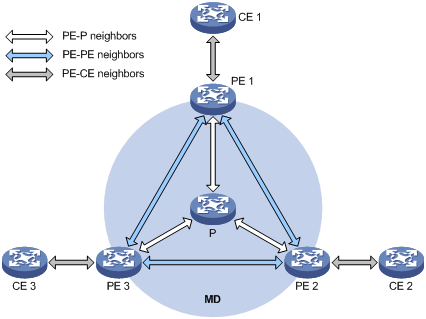
PIM neighboring relationships are established between two or more directly interconnected devices on the same subnet. As shown in Figure 4, the following types of PIM neighboring relationships exist in MD-VPN, as follows:
· PE-P neighboring relationship—PIM neighboring relationship established between the public network interface on a PE device and an interface on the P device across the link.
· PE-PE neighboring relationship—PIM neighboring relationship established after a VPN instance on a PE device receives a PIM hello from a VPN instance on a remote PE device through an MTI.
· PE-CE neighboring relationship—PIM neighboring relationship established between a VPN-instance-associated interface on a PE device and an interface on a peer CE device.
Protocols and standards
· RFC 4684, Constrained Route Distribution for Border Gateway Protocol/MultiProtocol Label Switching (BGP/MPLS) Internet Protocol (IP) Virtual Private Networks (VPNs)
· draft-rosen-vpn-mcast-08, Multicast in MPLS/BGP IP VPNs
How MD-VPN works
This section describes how the MD-VPN technology is implemented, including the construction of a share-MDT, delivery of multicast traffic based on the share-MDT, and implementation of multi-AS MD-VPN.
For a VPN instance, multicast data transmission in the public network is transparent. The MTIs at the local PE device and the remote PE device form a channel for the seamless transmission of VPN data over the public network. All that is known to the VPN instance is that the VPN data is sent out the MTI and then the remote site can receive the data through the MTI. Actually, the multicast data transmission process (the MDT transmission process) over the public network is very complicated.
Share-MDT establishment
The multicast routing protocol running in the public network can be PIM-DM, PIM-SM, BIDIR-PIM, or PIM-SSM. The process of creating a share-MDT is different in these PIM modes.
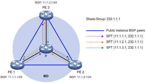
Share-MDT establishment in a PIM-DM network
Figure 5 Share-MDT establishment in a PIM-DM network
As shown in Figure 5, PIM-DM is enabled in the network and all the PE devices support VPN instance A. The process of establishing a share-MDT is as follows:
The public network on PE 1 initiates a flood-prune process in the entire public network, with the BGP interface address (namely the interface address used to establish the BGP peer) as the multicast source address and the share-group address as the multicast group address. All the other PE devices that are running VPN instance A are group members, so that a (11.1.1.1, 239.1.1.1) state entry is created on each device along the path in the public network. This forms an SPT with PE 1 as the root, and PE 2 and PE 3 as leaves.
At the same time, PE 2 and PE 3 respectively initiate a similar flood-prune process. Finally, three independent SPTs are established in the MD. In the PIM-DM network, these independent SPTs constitute a share-MDT.
Share-MDT establishment in a PIM-SM network
Figure 6 Share-MDT establishment in a PIM-SM network
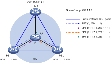
As shown in Figure 6, PIM-SM is enabled in the network and all the PE devices support VPN instance A. The process of establishing a share-MDT is as follows:
1. The public network on PE 1 initiates a join to the public network RP, with the share-group address as the multicast group address in the join message, and a (*, 239.1.1.1) state entry is created on each device along the path in the public network. At the same time, PE 2 and PE 3 respectively initiate a similar join process. Finally, an RPT is established in the MD, with the public network RP as the root and PE 1, PE 2 and PE 3 as leaves.
2. The public network on PE 1 registers the multicast source with the public network RP and the public network RP initiates a join to PE 1. With the BGP interface address as the multicast source address and the share-group address as the multicast group address, a (11.1.1.1, 239.1.1.1) state entry is created on each device along the path in the public network. At the same time, PE 2 and PE 3 respectively initiate a similar register process. Finally, three SPTs between the PE devices and the RP are established in the MD.
In the PIM-SM network, the RPT—namely, the (*, 239.1.1.1) tree—and the three independent SPTs constitute a share-MDT.
Share-MDT establishment in a BIDIR-PIM network
Figure 7 Share-MDT establishment in a BIDIR-PIM network
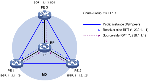
As shown in Figure 7, BIDIR-PIM is enabled in the network and all the PE devices support VPN instance A. The process of establishing a share-MDT is as follows:
1. The public network on PE 1 initiates a join to the public network RP, with the share-group address as the multicast group address in the join message, and a (*, 239.1.1.1) entry is created on each device along the path in the public network. At the same time, PE 2 and PE 3 respectively initiate a similar join process. Finally, the receiver-side RPT is established in the MD, with the public network RP as the root and PE 1, PE 2 and PE 3 as leaves.
2. The public network on PE 1 sends multicast data, with the share-group address as the destination multicast group address. The DF on each subnet that the multicast data travels through in the public network unconditionally forwards the data to the RP, and a (*, 239.1.1.1) entry is created on each device along the path. At the same time, PE 2 and PE 3 respectively initiate a similar process. Finally, the source-side RPT is established in the MD, with PE 1, PE 2, and PE 3 as the roots and the public network RP as the leave.
In the BIDIR-PIM network, the receiver-side RPT and the source-side RPT constitute a bi-directional RPT—namely, the (*, 239.1.1.1) tree, which is a share-MDT.
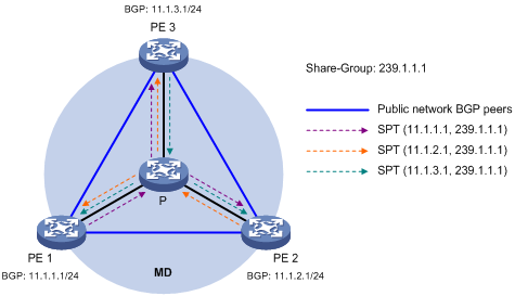
Share-MDT establishment in a PIM-SSM network
Figure 8 Share-MDT establishment in a PIM-SSM network
As shown in Figure 8, PIM-SSM is enabled in the network and all the PE devices support VPN instance A. The process of establishing a share-MDT is as follows:
The public network on PE 1 sends the local BGP MDT routing information, including its BGP interface address and the share-group address, to PE 2 and PE 3. PE 2 and PE 3 perform the same operation to exchange their BGP MDT routing information with one another. After receiving the BGP MDT information from PE1, PE 2 and PE 3 respectively send a subscribe message for channel subscription hop by hop toward the BGP interface of PE1. A (11.1.1.1, 232.1.1.1) entry is created on devices on the path toward PE 1 in the public network. Thus an SPT is created in the network, with PE 1 as its root, PE 2 and PE 3 as its leaves.
At the same time, PE 2 and PE 3 respectively initiate a similar SPT establishment process. Finally, three independent SPTs are established in the MD. In the PIM-SS M network, the three independent SPTs constitute a share-MDT.
|
|
NOTE: In PIM-SSM, subscribe messages are used equivalent to join messages. |
Characteristics of a share-MDT
A share-MDT is characterized as follows, no matter what PIM mode is running in the public network:
· All PE devices that support this VPN instance join the share-MDT.
Share-MDT-based delivery
A share-MDT can be used for delivering multicast packets, including both multicast protocol packets and multicast data packets. However, the transmission processes for these two types of multicast packets are different.
Delivery of multicast protocol packets
To forward the multicast protocol packets of a VPN over the public network, the local PE device encapsulates them into public-network multicast data packets. These packets are transmitted along the share-MDT, and then de-encapsulated on the remote PE device to go into the normal protocol procedure. Finally a distribution tree is established across the public network. The following describes how multicast protocol packets are forwarded in the following circumstances:
1. If the VPN network runs PIM-DM or PIM-SSM:
¡ Hello packets are forwarded among MTI interfaces to establish PIM neighboring relationships.
¡ A flood-prune process (in PIM-DM) or a join process (in PIM-SSM) is initiated across the public network to establish an SPT across the public network.
2. If the VPN network runs PIM-SM:
¡ Hello packets are forwarded among MTI interfaces to establish PIM neighboring relationships.
¡ If the receivers and the VPN RP are in different sites, a join process is initiated across the public network to establish an RPT.
¡ If the multicast source and the VPN RP are in different sites, a registration process is initiated across the public network to establish an SPT.
3. If the VPN network runs BIDIR-PIM:
¡ Hello packets are forwarded among MTI interfaces to establish PIM neighboring relationships.
¡ If the receivers and the VPN RP are in different sites, a join process is initiated across the public network to establish the receiver-side RPT.
¡ If the multicast source and the VPN RP are in different sites, multicast data is transmitted across the public network to establish the source-side RPT.
|
|
NOTE: · All interfaces that belong to the same VPN, including those interfaces with VPN instance bindings and the MTI on PE devices, must run the same PIM mode. · The following example explains how multicast protocol packets are delivered based on the share-MDT when PIM-SM is running in both the public network and the VPN network, with receivers and the VPN RP located in different sites. |
As shown in Figure 9, PIM-SM is running in both the public network and the VPN network, Receiver for the VPN multicast group G (225.1.1.1) in Site 2 is attached to CE 2, and CE 1 of Site 1 acts as the RP for group G (225.1.1.1); the share-group address used to forward public network data is 239.1.1.1.
Figure 9 Transmission of multicast protocol packets
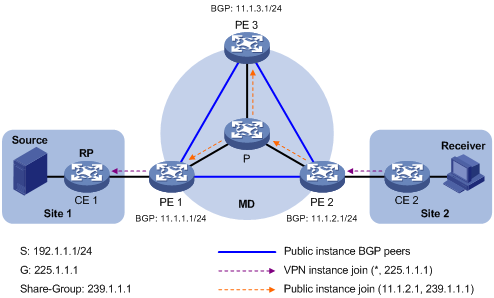
The work process of multicast protocol packets is as follows:
1. Receiver sends an IGMP membership report for multicast group G to CE 2. CE 2 creates a local (*, 225.1.1.1) state entry and sends a join message to the VPN RP (CE 1).
2. After receiving the join message from CE 2, the VPN instance on PE 2 creates a (*, 225.1.1.1) state entry with the upstream interface being the MTI, and then PE 2 processes the join message. Now, the VPN instance on PE 2 considers that the join message has been sent out the MTI.
3. PE 2 encapsulates the join message by means of Generic Routing Encapsulation (GRE), with its BGP interface address as the multicast source address and the share-group address as the multicast group address, to convert it into a normal, public network multicast data packet (11.1.2.1, 239.1.1.1). PE 2 then forwards it to the public network.
4. The multicast data packet (11.1.2.1, 239.1.1.1) is forwarded to the public network on all the PE devices along the share-MDT. After receiving this packet, every PE device decapsulates it to turn it back into a join message to be sent to the VPN RP. Then, each PE device checks the join message. If any PE device finds that the VPN RP is in the site it interfaces with, it passes the join message to the VPN instance on it. Otherwise, it discards the join message.
5. When receiving the join message, the VPN instance on PE 1 considers that it received the message from the MTI. PE 1 creates a local (*, 225.1.1.1) state entry, with the downstream interface being the MTI and the upstream interface being the one that leads to CE 1. At the same time, it sends a join message to CE 1, which is the VPN RP.
6. After receiving the join message from the VPN instance on PE 1, CE 1 creates a local (*, 225.1.1.1) state entry or updates the entry if it already exists. By now, the construction of an RPT across the public network is completed.
|
|
NOTE: For more information about GRE, see Layer 3—IP Services Configuration Guide. |
Delivery of multicast data packets
After the share-MDT is established, the multicast source forwards the VPN multicast data to the receivers in each site along the distribution tree. The VPN multicast packets are encapsulated into public network multicast packets on the local PE device, transmitted along the share-MDT, and then decapsulated on the remote PE device and transmitted in that VPN site. VPN multicast data flows are forwarded across the public network differently in the following circumstances:
1. If PIM-DM or PIM-SSM is running in the VPN, the multicast source forwards multicast data to the receivers along the VPN SPT across the public network.
2. When PIM-SM is running in the VPN:
¡ Before SPT switchover, if the multicast source and the VPN RP are in different sites, the multicast source forwards VPN multicast data to the VPN RP along the VPN SPT across the public network. If the VPN RP and the receiver are in different sites, the VPN RP forwards VPN multicast traffic to the receiver along the VPN RPT over the public network.
¡ After SPT switchover, if the multicast source and the receiver are in different sites, the multicast source forwards VPN multicast data to the receiver along the VPN SPT across the public network.
3. When BIDIR-PIM is running in the VPN, if the multicast source and the VPN RP are in different sites, the multicast source sends multicast data to the VPN RP across the public network along the source-side RPT. If the VPN RP and the receivers are in different sites, the VPN RP forwards the multicast data to the receivers across the public network along the receiver-side RPT.
|
|
NOTE: · For more information about RPT-to-SPT switchover, see the chapter “Configuring PIM.” · The following example explains how multicast data packets are delivered based on the share-MDT when PIM-DM is running in both the public network and the VPN network. |
As shown in Figure 10, PIM-DM is running in both the public network and the VPN sites, Receiver of the VPN multicast group G (225.1.1.1) in Site 2 is attached to CE 2, and Source in Site 1 sends multicast data to multicast group G); the share-group address used to forward public network multicast data is 239.1.1.1.
Figure 10 Delivery of multicast data packets
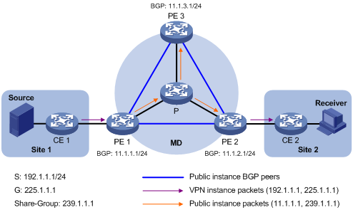
The VPN multicast traffic is delivered across the public network as follows.
1. Source sends customer multicast data (192.1.1.1, 225.1.1.1) to CE 1.
2. CE 1 forwards the VPN multicast data along an SPT to CE 1, and the VPN instance on PE 1 checks the MVRF. If the outgoing interface list of the forwarding entry contains an MTI, PE 1 processes the VPN multicast data.. Now, the VPN instance on PE 1 considers that the VPN multicast data has been sent out the MTI.
3. PE 1 encapsulates the multicast data by means of GRE, with its BGP interface address as the multicast source address and the share-group address as the multicast group address, to convert it into a normal, public network multicast data packet (11.1.1.1, 239.1.1.1). PE 1 then forwards it to the public network.
4. The multicast data packet (11.1.1.1, 239.1.1.1) is forwarded to the public network on all the PE devices along the share-MDT. After receiving this packet, every PE device decapsulates it to turn it back into a VPN multicast data packet, and passes it to the corresponding VPN instance. If any PE has a downstream interface for an SPT, it forwards the VPN multicast packet down the SPT. Otherwise, it discards the packet.
MDT switchover
Switching from share-MDT to switch-MDT
When a multicast data packet of a VPN is transmitted through the share-MDT in the public network, the packet is forwarded to all PE devices that support that VPN instance, no matter whether any active receivers exist in the attached sites. When the rate of the customer multicast traffic of that VPN is high, multicast data might get flooded in the public network, causing bandwidth waste and extra burden on the PE devices.
To optimize multicast transmission, the MD solution establishes a dedicated switch-MDT between the PE devices with VPN multicast receivers and multicast sources for any large-traffic VPN multicast stream before it enters the public network. Then, the multicast stream is switched from the share-MDT to the switch-MDT, to deliver the multicast data to only those receivers that need it.
The process of share-MDT to switch-MDT switchover is as follows:
1. The source-side PE (PE 1 in this example) device periodically checks the forwarding rate of the VPN multicast traffic. Share-MDT to switch-MDT switchover takes place only when the following criteria are both met:
¡ The VPN multicast data has passed the filtering by an ACL rule for share-MDT to switch-MDT switchover, and
¡ The traffic rate of the VPN multicast stream has exceeded the switchover threshold and stayed higher than the threshold for a certain length of time.
2. PE 1 chooses an idle switch-group address from the switch-group-pool and sends an MDT switchover message to all the other PE devices down the share-MDT. This message contains the VPN multicast source address, the VPN multicast group address and the switch-group address.
3. Each PE device that receives this message checks whether it interfaces with a VPN that has receivers of that VPN multicast stream. If so, it joins the switch-MDT rooted at PE 1. Otherwise, it caches the message and will join the switch-MDT when it has attached receivers.
4. After sending the MDT switchover message, PE 1 waits a certain length of time and then starts using the switch-group address to encapsulate the VPN multicast data, so that the multicast data is forwarded down the switch-MDT.
5. After the multicast traffic is switched from the share-MDT to the switch-MDT, PE 1 continues sending MDT switchover messages periodically, so that subsequent PE devices with attached receivers can join the switch-MDT. When a downstream PE device has no longer active receivers attached to it, it leaves the switch-MDT.
|
|
NOTE: For a given VPN instance, the share-MDT and the switch-MDT are both forwarding tunnels in the same MD. A share-MDT is uniquely identified by a share-group address, and a switch-MDT is uniquely identified by a switch-group address. Each share-group is uniquely associated with a set of switch-group addresses, namely, a switch-group-pool. |
Backward switching from switch-MDT to share-MDT
After the VPN multicast traffic is switched to the switch-MDT, the multicast traffic conditions might change and no longer meet the aforesaid switchover criterion. In this case, PE 1, as in the preceding example, initiates a backward MDT switchover process. When any of the following criteria is met, the multicast traffic is switched from the switch-MDT back to the share-MDT:
· The associated switch-group-pool is changed and the switch-group address for encapsulating the VPN multicast data is out of the new address pool.
· The ACL rule for controlling the switching of VPN multicast traffic from the share-MDT to the switch-MDT is changed and the VPN multicast data fails to pass the new ACL rule.
Multi-AS MD VPN
If nodes of a VPN network are allocated in multiple autonomous systems (ASs), these VPN nodes must be interconnected. To implement multi-AS VPN, VRF-to-VRF PE interconnectivity and multi-hop EBGP interconnectivity are available.
VRF-to-VRF PE interconnectivity
As shown in Figure 11, a VPN involves AS 1 and AS 2. PE 3 and PE 4 are the autonomous system boundary router (ASBR) for AS 1 and AS 2 respectively. PE 3 and PE 4 are interconnected through their respective VPN instance and treat each other as a CE device.
Figure 11 VPN instance-VPN instance interconnectivity
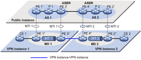
In the VPN instance-to-VPN instance interconnectivity approach, a separate MD must be established within each AS, and VPN multicast traffic between different ASs is transmitted between these MDs.
|
|
NOTE: Because only VPN multicast traffic is forwarded between ASBRs, different PIM modes can run within different ASs. However, the same PIM mode (PIM-DM, PIM-SM, BIDIR-PIM, or PIM-SSM) must run on all interfaces that belong to the same VPN (including interfaces with VPN bindings on ASBRs). |
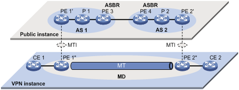
Multi-hop EBGP interconnectivity
As shown in Figure 12, a VPN network involves AS 1 and AS 2. PE 3 and PE 4 are the autonomous system boundary router (ASBR) for AS 1 and AS 2 respectively. PE 3 and PE 4 are interconnected through their respective public network instance and treat each other as a P device.
Figure 12 Multi-hop EBGP interconnectivity
Multicast VPN configuration task list
|
|
CAUTION: When the system operates in standard mode, a reserved VLAN must be configured if multicast VPN will be configured. Otherwise, abnormality may occur in the system. After a reserved VLAN is configured, any change to it will incur reconfiguration of the reserved VLAN. For how to configure a reserved VLAN, see MPLS Configuration Guide and MPLS Command Reference. |
Complete these tasks to configure multicast VPN:
|
Task |
Remarks |
|
|
Required |
||
|
Required |
||
|
Optional |
||
Configuring MD-VPN
Configuration prerequisites
Before you configure MD-VPN, complete the following tasks:
· Configure any unicast routing protocol to provide intra-domain interoperability at the network layer
· Configure PIM (PIM-DM, PIM-SM, BIDIR-PIM, or PIM-SSM)
· Determine the VPN instance names and route distinguishers (RDs)
· Determine the share-group addresses and an MTI numbers
· Determine the address ranges of switch-group-pools and ACL rules for MDT switchover
· Determine the switch-delay period
· Determine the switch-holddown period
Enabling IP multicast routing in a VPN instance
Before you configure any MD-VPN functionality for a VPN, you must enable IP multicast routing in the VPN instance.
To enable IP multicast routing in a VPN instance:
|
Step |
Command |
Remarks |
|
1. Enter system view. |
system-view |
N/A |
|
2. Create a VPN instance and enter VPN instance view. |
ip vpn-instance vpn-instance-name |
N/A |
|
3. Configure an RD for the VPN instance. |
route-distinguisher route-distinguisher |
No RD is configured for a VPN instance by default. |
|
4. Enable IP multicast routing. |
multicast routing-enable |
Configuring a share-group and an MTI binding
By running multiple instances on each PE device, you enable the PE device to work for multiple VPNs. You must configure the same share-group address for the same VPN instance on different PE devices. With a share-group and an MTI number configured, the system automatically creates an MTI, binds the share-group address to the MTI, and binds the MTI to the current VPN instance.
To configure a share-group and an MTI binding:
|
Step |
Command |
Remarks |
|
1. Enter system view. |
system-view |
N/A |
|
2. Enter VPN instance view. |
ip vpn-instance vpn-instance-name |
N/A |
|
3. Configure a share-group address and an MTI binding. |
multicast-domain share-group group-address binding mtunnel mtunnel-number |
No share-group address or MTI binding is configured. |
Configuring MDT switchover parameters
To avoid frequent switching of multicast traffic between the share-MDT and the switch-MDT:
MDT switchover does not take place immediately after the first private network multicast packet is received, but it takes place after a switch-delay period has passed, during which transmission of private network multicast streams has lasted.
To configure MDT switchover parameters:
|
Step |
Command |
Remarks |
|
1. Enter system view. |
system-view |
N/A |
|
2. Enter VPN instance view. |
ip vpn-instance vpn-instance-name |
N/A |
|
3. Configure the switch-group-pool address range and the switchover criteria. |
multicast-domain switch-group-pool switch-group-pool { mask | mask-length } [ acl acl-number ] |
By default, no switch-group-pool is configured and multicast traffic is never switched to a switch-MDT. |
|
4. Configure the switch-delay period. |
multicast-domain switch-delay switch-delay |
Optional. 5 seconds by default. |
|
5. Configure the switch-holddown period. |
multicast-domain holddown-time interval |
Optional. 60 seconds by default. |
Enabling switch-group reuse logging
For a given VPN, if the number of VPN multicast streams to be switched to switch-MDTs exceeds the number of addresses in the switch-group-pool, the VPN instance on the source-side PE device can reuse the addresses in the address pool. With switch-group reuse logging enabled, the address reuse information will be logged.
To enable the switch-group reuse logging:
|
Step |
Command |
Remarks |
|
1. Enter system view. |
system-view |
N/A |
|
2. Enter VPN instance view. |
ip vpn-instance vpn-instance-name |
N/A |
|
3. Enable the switch-group reuse logging. |
multicast-domain log switch-group-reuse |
Disabled by default |
|
|
NOTE: · Attributed to the MD module, the group address reuse logging information has a severity level of informational. For more information about the logging information, see Network Management and Monitoring Configuration Guide. · With switch-group reuse logging enabled, the generated group address reuse logging information will be sent to the information center, where you can configure the rules for outputting the logging information. For more information about the configuration of the information center, see Network Management and Monitoring Configuration Guide. |
Configuring BGP MDT
If PIM-SSM is running in the public network, you need to configure BGP MDT.
Configuration prerequisites
Before you configure BGP MDT, complete the following tasks:
· Configure MPLS L3VPN
· Configure basic BGP functions
· Determine the route reflector cluster ID
Configuring BGP MDT peers or peer groups
With BGP MDT peers or peer groups configured, a PE exchanges the BGP MDT routing information with other PEs to obtain their addresses and thus establish a share-MDT.
|
|
NOTE: · A BGP MDT peer or peer group is a peer or peer group created in BGP-MDT subaddress family view. · Configure the BGP MDT peer or peer group before enabling it. |
To configure BGP MDT peers or peer groups:
|
Step |
Command |
Remarks |
|
1. Enter system view. |
system-view |
N/A |
|
2. Enter BGP view. |
bgp as-number |
N/A |
|
3. Enter BGP MDT sub-address family view. |
ipv4-family mdt |
N/A |
|
4. Enable a BGP MDT peer or peer group. |
peer { group-name | ip-address } enable |
Disabled by default. |
|
5. Add a peer to the BGP MDT peer group. |
peer ip-address group group-name |
Optional. By default, a BGP MDT peer belongs to no peer groups. |
Configuring a BGP MDT route reflector
BGP MDT peers in the same AS must be fully meshed to maintain connectivity. However, when many BGP MDT peers exist in an AS, connection establishment among them might cause great expenses. To reduce connections between them, you can configure one of them as a route reflector and specify other routers as clients. The clients establish BGP MDT connections with the route reflector, and the route reflector forwards (reflects) BGP MDT routing information between clients. In this way, the clients need not to be fully meshed. Furthermore, you can disable client-to-client reflection to reduce overloads if the clients have been fully meshed.
The route reflector and its clients form a cluster. In general, a cluster has only one route reflector whose router ID identifies the cluster. However, you can configure several route reflectors in a cluster to improve network reliability, and they must have the same cluster ID configured to avoid routing loops.
To configure a BGP MDT route reflector:
|
Step |
Command |
Remarks |
|
1. Enter system view. |
system-view |
N/A |
|
2. Enter BGP view. |
bgp as-number |
N/A |
|
3. Enter BGP MDT sub-address family view. |
ipv4-family mdt |
N/A |
|
4. Configure the local device as a route reflector and specify its clients. |
peer { group-name | ip-address } reflect-client |
By default, neither route reflectors nor clients exist. |
|
5. Disable route reflection between clients. |
undo reflect between-clients |
Optional. Enabled by default. |
|
6. Configure the cluster ID of the route reflector. |
reflector cluster-id { cluster-id | ip-address } |
Optional. By default, a route reflector uses its router ID as the cluster ID. |
Displaying and maintaining multicast VPN
|
Task |
Command |
Remarks |
|
Display the share-group information of the specified VPN instance in the MD. |
display multicast-domain vpn-instance vpn-instance-name share-group { local | remote } [ | { begin | exclude | include } regular-expression ] |
Available in any view |
|
Display the switch-group information received by the specified VPN instance in the MD. |
display multicast-domain vpn-instance vpn-instance-name switch-group receive [ brief | [ active | group group-address | sender source-address | vpn-source-address [ mask { mask-length | mask } ] | vpn-group-address [ mask { mask-length | mask } ] ] * ] [ | { begin | exclude | include } regular-expression ] |
Available in any view |
|
Display the switch-group information sent by the specified VPN instance in the MD. |
display multicast-domain vpn-instance vpn-instance-name switch-group send [ group group-address | reuse interval | vpn-source-address [ mask { mask-length | mask } ] | vpn-group-address [ mask { mask-length | mask } ] ] * [ | { begin | exclude | include } regular-expression ] |
Available in any view |
|
Display the information of the BGP MDT peer group(s). |
display bgp mdt group [ group-name ] [ | { begin | exclude | include } regular-expression ] |
Available in any view |
|
Display the information of the BGP MDT peers. |
display bgp mdt peer [ [ ip-address ] verbose ] [ | { begin | exclude | include } regular-expression ] |
Available in any view |
|
Display the BGP MDT routing information. |
display bgp mdt { all | route-distinguisher route-distinguisher } routing-table [ ip-address [ mask | mask-length ] ] [ | { begin | exclude | include } regular-expression ] |
Available in any view |
|
Reset the BGP MDT connections. |
reset bgp mdt { as-number | ip-address | all | external | group group-name | internal } |
Available in user view |
Multicast VPN configuration examples
|
|
NOTE: By default, Ethernet interfaces, VLAN interfaces, and aggregate interfaces are in the state of DOWN. To configure such an interface, use the undo shutdown command to bring it up first |
Single-AS MD VPN configuration
Network requirements
|
Item |
Network requirements |
|
Multicast sources and receivers |
· In VPN a, S 1 is a multicast source, and R 1, R 2 and R3 are receivers. · In VPN b, S 2 is a multicast source, and R 4 is a receiver. · For VPN a, the share-group address is 239.1.1.1, and the switch-group-pool address range is 225.2.2.0 to 225.2.2.15. · For VPN b, the share-group address is 239.2.2.2, and the switch-group-pool address range is 225.4.4.0 to 225.4.4.15. |
|
PE interfaces and VPN instances they belong to |
· PE 1: VLAN-interface 11 and VLAN-interface 20 belong to VPN instance a; VLAN-interface 12 and Loopback 1 belong to the public network instance. · PE 2: VLAN-interface 13 belongs to VPN instance b; VLAN-interface 14 belongs to VPN instance a; VLAN-interface 15 and Loopback 1 belong to the public network instance. · PE 3: VLAN-interface 17 belongs to VPN instance a; VLAN-interface 18 and Loopback 2 belong to VPN instance b; VLAN-interface 19 and Loopback 1 belong to the public network instance. |
|
Unicast routing protocols and MPLS |
· Configure OSPF in the public network, and configure RIP between the PEs and CEs. · Establish BGP peer connections between PE 1, PE 2 and PE 3 on their respective Loopback 1 interface and exchange all VPN routes between them. · Configure MPLS in the public network. |
|
IP multicast routing |
· Enable IP multicast routing on the P device. · Enable IP multicast routing on the public network on PE 1, PE 2, and PE 3. · Enable IP multicast routing in VPN instance a on PE 1, PE 2, and PE 3. · Enable IP multicast routing in VPN instance b on PE 2 and PE 3. · Enable IP multicast routing on CE a1, CE a2, CE a3, CE b1, and CE b2. |
|
IGMP |
· Run IGMPv2 on VLAN-interface 20 of PE 1. · Run IGMPv2 on VLAN-interface 40 of CE a2, VLAN-interface 50 of CE a3, and VLAN-interface 60 of CE b2. |
|
PIM |
· Enable PIM-SM on all interfaces of the P device. · Enable PIM-SM on all public and private network interfaces of PE 1, PE 2 and PE 3. · Enable PIM-SM on all interfaces of CE a1, CE a2, CE a3, CE b1, and CE b2. · Configure Loopback 1 of P as a C-BSR and a C-RP for the public network (to work for all multicast groups). · Configure Loopback 1 of CE a2 as a C-BSR and a C-RP for VPN a (to work for all multicast groups). · Configure Loopback 2 of PE 3 as a C-BSR and a C-RP for VPN b (to work for all multicast groups). |
Figure 13 Network diagram
|
Device |
Interface |
IP address |
Device |
Interface |
IP address |
|
S 1 |
— |
10.110.7.2/24 |
PE 3 |
Vlan-int19 |
192.168.8.1/24 |
|
S 2 |
— |
10.110.8.2/24 |
|
Vlan-int17 |
10.110.5.1/24 |
|
R 1 |
— |
10.110.1.2/24 |
|
Vlan-int18 |
10.110.6.1/24 |
|
R 2 |
— |
10.110.9.2/24 |
|
Loop1 |
1.1.1.3/32 |
|
R 3 |
— |
10.110.10.2/24 |
|
Loop2 |
33.33.33.33/32 |
|
R 4 |
— |
10.110.11.2/24 |
CE a1 |
Vlan-int10 |
10.110.7.1/24 |
|
P |
Vlan-int12 |
192.168.6.2/24 |
|
Vlan-int11 |
10.110.2.2/24 |
|
|
Vlan-int15 |
192.168.7.2/24 |
CE a2 |
Vlan-int40 |
10.110.9.1/24 |
|
|
Vlan-int19 |
192.168.8.2/24 |
|
Vlan-int14 |
10.110.4.2/24 |
|
|
Loop1 |
2.2.2.2/32 |
|
Vlan-int16 |
10.110.12.1/24 |
|
PE 1 |
Vlan-int12 |
192.168.6.1/24 |
|
Loop1 |
22.22.22.22/32 |
|
|
Vlan-int20 |
10.110.1.1/24 |
CE a3 |
Vlan-int50 |
10.110.10.1/24 |
|
|
Vlan-int11 |
10.110.2.1/24 |
|
Vlan-int17 |
10.110.5.2/24 |
|
|
Loop1 |
1.1.1.1/32 |
|
Vlan-int16 |
10.110.12.2/24 |
|
PE 2 |
Vlan-int15 |
192.168.7.1/24 |
CE b1 |
Vlan-int30 |
10.110.8.1/24 |
|
|
Vlan-int13 |
10.110.3.1/24 |
|
Vlan-int13 |
10.110.3.2/24 |
|
|
Vlan-int14 |
10.110.4.1/24 |
CE b2 |
Vlan-int60 |
10.110.11.1/24 |
|
|
Loop1 |
1.1.1.2/32 |
|
Vlan-int18 |
10.110.6.2/24 |
Configuration procedure
1. Configure PE 1:
# Configure a Router ID, enable IP multicast routing on the public network, configure an MPLS LSR ID, and enable the LDP capability.
<PE1> system-view
[PE1] router id 1.1.1.1
[PE1] multicast routing-enable
[PE1] mpls lsr-id 1.1.1.1
[PE1] mpls
[PE1-mpls] quit
[PE1] mpls ldp
[PE1-mpls-ldp] quit
# Create VPN instance a, configure a RD for it, and create an egress route and an ingress route for it.
[PE1] ip vpn-instance a
[PE1-vpn-instance-a] route-distinguisher 100:1
[PE1-vpn-instance-a] vpn-target 100:1 export-extcommunity
[PE1-vpn-instance-a] vpn-target 100:1 import-extcommunity
# Enable IP multicast routing in VPN instance a, configure a share-group address, associate an MTI with the VPN instance, and define the switch-group-pool address range.
[PE1-vpn-instance-a] multicast routing-enable
[PE1-vpn-instance-a] multicast-domain share-group 239.1.1.1 binding mtunnel 0
[PE1-vpn-instance-a] multicast-domain switch-group-pool 225.2.2.0 28
[PE1-vpn-instance-a] quit
# Configure an IP address, and enable PIM-SM and LDP capability on the public network interface VLAN-interface 12.
[PE1] interface vlan-interface 12
[PE1-Vlan-interface12] ip address 192.168.6.1 24
[PE1-Vlan-interface12] pim sm
[PE1-Vlan-interface12] mpls
[PE1-Vlan-interface12] mpls ldp
[PE1-Vlan-interface12] quit
# Bind VLAN-interface 20 with VPN instance a, configure an IP address and enable IGMP and PIM-SM on the interface.
[PE1] interface vlan-interface 20
[PE1-Vlan-interface20] ip binding vpn-instance a
[PE1-Vlan-interface20] ip address 10.110.1.1 24
[PE1-Vlan-interface20] igmp enable
[PE1-Vlan-interface20] pim sm
[PE1-Vlan-interface20] quit
# Bind VLAN-interface 11 with VPN instance a, configure an IP address and enable PIM-SM on the interface.
[PE1] interface vlan-interface 11
[PE1-Vlan-interface11] ip binding vpn-instance a
[PE1-Vlan-interface11] ip address 10.110.2.1 24
[PE1-Vlan-interface11] pim sm
[PE1-Vlan-interface11] quit
# Configure an IP address for Loopback 1, and enable PIM-SM.
[PE1] interface loopback 1
[PE1-LoopBack1] ip address 1.1.1.1 32
[PE1-LoopBack1] pim sm
[PE1-LoopBack1] quit
# Configure BGP.
[PE1] bgp 100
[PE1-bgp] group vpn-g internal
[PE1-bgp] peer vpn-g connect-interface loopback 1
[PE1-bgp] peer 1.1.1.2 group vpn-g
[PE1-bgp] peer 1.1.1.3 group vpn-g
[PE1–bgp] ipv4-family vpn-instance a
[PE1-bgp-a] import-route rip 2
[PE1-bgp-a] import-route direct
[PE1-bgp-a] quit
[PE1–bgp] ipv4-family vpnv4
[PE1–bgp-af-vpnv4] peer vpn-g enable
[PE1-bgp-af-vpnv4] peer 1.1.1.2 group vpn-g
[PE1–bgp-af-vpnv4] peer 1.1.1.3 group vpn-g
[PE1–bgp-af-vpnv4] quit
[PE1–bgp] quit
With BGP peers configured on PE 1, the interfaces MTI 0 will automatically obtain an IP address, which is the loopback interface address specified in the BGP peer configuration. The PIM mode running on MTI 0 is the same as on the interfaces in VPN instance a.
# Configure OSPF.
[PE1] ospf 1
[PE1-ospf-1] area 0.0.0.0
[PE1-ospf-1-area-0.0.0.0] network 1.1.1.1 0.0.0.0
[PE1-ospf-1-area-0.0.0.0] network 192.168.0.0 0.0.255.255
[PE1-ospf-1-area-0.0.0.0] quit
[PE1-ospf-1] quit
# Configure RIP
[PE1] rip 2 vpn-instance a
[PE1-rip-2] network 10.0.0.0
[PE1-rip-2] import-route bgp
[PE1-rip-2] return
2. Configure PE 2:
# Configure a Router ID, enable IP multicast routing on the public network, configure an MPLS LSR ID, and enable the LDP capability.
<PE2> system-view
[PE2] router id 1.1.1.2
[PE2] multicast routing-enable
[PE2] mpls lsr-id 1.1.1.2
[PE2] mpls
[PE2-mpls] quit
[PE2] mpls ldp
[PE2-mpls-ldp] quit
# Create VPN instance b, configure a RD for it, and create an egress route and an ingress route for it.
[PE2] ip vpn-instance b
[PE2-vpn-instance-b] route-distinguisher 200:1
[PE2-vpn-instance-b] vpn-target 200:1 export-extcommunity
[PE2-vpn-instance-b] vpn-target 200:1 import-extcommunity
# Enable IP multicast routing in VPN instance b, configure a share-group address, associate an MTI with the VPN instance, and define the switch-group-pool address range.
[PE2-vpn-instance-b] multicast routing-enable
[PE2-vpn-instance-b] multicast-domain share-group 239.2.2.2 binding mtunnel 1
[PE2-vpn-instance-b] multicast-domain switch-group-pool 225.4.4.0 28
[PE2-vpn-instance-b] quit
# Create VPN instance a, configure a RD for it, and create an egress route and an ingress route for it.
[PE2] ip vpn-instance a
[PE2-vpn-instance-a] route-distinguisher 100:1
[PE2-vpn-instance-a] vpn-target 100:1 export-extcommunity
[PE2-vpn-instance-a] vpn-target 100:1 import-extcommunity
# Enable IP multicast routing in VPN instance a, configure a share-group address, associate an MTI with the VPN instance, and define the switch-group-pool address range.
[PE2-vpn-instance-a] multicast routing-enable
[PE2-vpn-instance-a] multicast-domain share-group 239.1.1.1 binding mtunnel 0
[PE2-vpn-instance-a] multicast-domain switch-group-pool 225.2.2.0 28
[PE2-vpn-instance-a] quit
# Configure an IP address, and enable PIM-SM and LDP capability on the public network interface VLAN-interface 15.
[PE2] interface vlan-interface 15
[PE2-Vlan-interface15] ip address 192.168.7.1 24
[PE2-Vlan-interface15] pim sm
[PE2-Vlan-interface15] mpls
[PE2-Vlan-interface15] mpls ldp
[PE2-Vlan-interface15] quit
# Bind VLAN-interface 13 with VPN instance b, configure an IP address and enable PIM-SM on the interface.
[PE2] interface vlan-interface 13
[PE2-Vlan-interface13] ip binding vpn-instance b
[PE2-Vlan-interface13] ip address 10.110.3.1 24
[PE2-Vlan-interface13] pim sm
[PE2-Vlan-interface13] quit
# Bind VLAN-interface 14 with VPN instance a, configure an IP address and enable PIM-SM on the interface.
[PE2] interface vlan-interface 14
[PE2-Vlan-interface14] ip binding vpn-instance a
[PE2-Vlan-interface14] ip address 10.110.4.1 24
[PE2-Vlan-interface14] pim sm
[PE2-Vlan-interface14] quit
# Configure an IP address for Loopback 1, and enable PIM-SM.
[PE2] interface loopback 1
[PE2-LoopBack1] ip address 1.1.1.2 32
[PE2-LoopBack1] pim sm
[PE2-LoopBack1] quit
# Configure BGP.
[PE2] bgp 100
[PE2-bgp] group vpn-g internal
[PE2-bgp] peer vpn-g connect-interface loopback 1
[PE2-bgp] peer 1.1.1.1 group vpn-g
[PE2-bgp] peer 1.1.1.3 group vpn-g
[PE2–bgp] ipv4-family vpn-instance a
[PE2-bgp-a] import-route rip 2
[PE2-bgp-a] import-route direct
[PE2-bgp-a] quit
[PE2–bgp] ipv4-family vpn-instance b
[PE2-bgp-b] import-route rip 3
[PE2-bgp-b] import-route direct
[PE2-bgp-b] quit
[PE2–bgp] ipv4-family vpnv4
[PE2–bgp-af-vpnv4] peer vpn-g enable
[PE2-bgp-af-vpnv4] peer 1.1.1.1 group vpn-g
[PE2–bgp-af-vpnv4] peer 1.1.1.3 group vpn-g
[PE2–bgp-af-vpnv4] quit
[PE2–bgp] quit
With BGP peers configured on PE 2, the interfaces MTI 0 and MTI 1 will automatically obtain IP addresses, which are the loopback interface addresses specified in the BGP peer configuration. The PIM mode running on MTI 0 is the same as on the interfaces in VPN instance a, and the PIM mode running on MTI 1 is the same as on the interfaces in VPN instance b.
# Configure OSPF.
[PE2] ospf 1
[PE2-ospf-1] area 0.0.0.0
[PE2-ospf-1-area-0.0.0.0] network 1.1.1.2 0.0.0.0
[PE2-ospf-1-area-0.0.0.0] network 192.168.0.0 0.0.255.255
[PE2-ospf-1-area-0.0.0.0] quit
[PE2-ospf-1] quit
# Configure RIP
[PE2] rip 2 vpn-instance a
[PE2-rip-2] network 10.0.0.0
[PE2-rip-2] import-route bgp
[PE2-rip-2] quit
[PE2] rip 3 vpn-instance b
[PE2-rip-3] network 10.0.0.0
[PE2-rip-3] import-route bgp
[PE2-rip-3] return
3. Configure PE 3:
# Configure a Router ID, enable IP multicast routing on the public network, configure an MPLS LSR ID, and enable the LDP capability.
<PE3> system-view
[PE3] router id 1.1.1.3
[PE3] multicast routing-enable
[PE3] mpls lsr-id 1.1.1.3
[PE3] mpls
[PE3-mpls] quit
[PE3] mpls ldp
[PE3-mpls-ldp] quit
# Create VPN instance a, configure a RD for it, and create an egress route and an ingress route for it.
[PE3] ip vpn-instance a
[PE3-vpn-instance-a] route-distinguisher 100:1
[PE3-vpn-instance-a] vpn-target 100:1 export-extcommunity
[PE3-vpn-instance-a] vpn-target 100:1 import-extcommunity
# Enable IP multicast routing in VPN instance a, configure a share-group address, associate an MTI with the VPN instance, and define the switch-group-pool address range.
[PE3-vpn-instance-a] multicast routing-enable
[PE3-vpn-instance-a] multicast-domain share-group 239.1.1.1 binding mtunnel 0
[PE3-vpn-instance-a] multicast-domain switch-group-pool 225.2.2.0 28
[PE3-vpn-instance-a] quit
# Create VPN instance b, configure a RD for it, and create an egress route and an ingress route for it.
[PE3] ip vpn-instance b
[PE3-vpn-instance-b] route-distinguisher 200:1
[PE3-vpn-instance-b] vpn-target 200:1 export-extcommunity
[PE3-vpn-instance-b] vpn-target 200:1 import-extcommunity
# Enable IP multicast routing in VPN instance b, configure a share-group address, associate an MTI with the VPN instance, and define the switch-group-pool address range.
[PE3-vpn-instance-b] multicast routing-enable
[PE3-vpn-instance-b] multicast-domain share-group 239.2.2.2 binding mtunnel 1
[PE3-vpn-instance-b] multicast-domain switch-group-pool 225.4.4.0 28
[PE3-vpn-instance-b] quit
# Configure an IP address, and enable PIM-SM and LDP capability on the public network interface VLAN-interface 19.
[PE3] interface vlan-interface 19
[PE3-Vlan-interface19] ip address 192.168.8.1 24
[PE3-Vlan-interface19] pim sm
[PE3-Vlan-interface19] mpls
[PE3-Vlan-interface19] mpls ldp
[PE3-Vlan-interface19] quit
# Bind VLAN-interface 17 with VPN instance a, configure an IP address and enable PIM-SM on the interface.
[PE3] interface vlan-interface 17
[PE3-Vlan-interface17] ip binding vpn-instance a
[PE3-Vlan-interface17] ip address 10.110.5.1 24
[PE3-Vlan-interface17] pim sm
[PE3-Vlan-interface17] quit
# Bind VLAN-interface 18 with VPN instance b, configure an IP address and enable PIM-SM on the interface.
[PE3] interface vlan-interface 18
[PE3-Vlan-interface18] ip binding vpn-instance b
[PE3-Vlan-interface18] ip address 10.110.6.1 24
[PE3-Vlan-interface18] pim sm
[PE3-Vlan-interface18] quit
# Configure an IP address for Loopback 1, and enable PIM-SM.
[PE3] interface loopback 1
[PE3-LoopBack1] ip address 1.1.1.3 32
[PE3-LoopBack1] pim sm
[PE3-LoopBack1] quit
# Bind Loopback 2 with VPN instance b, configure an IP address and enable PIM-SM on the interface.
[PE3] interface loopback 2
[PE3-LoopBack2] ip binding vpn-instance b
[PE3-LoopBack2] ip address 33.33.33.33 32
[PE3-LoopBack2] pim sm
[PE3-LoopBack2] quit
# Configure Loopback 2 as a C-BSR and a C-RP for VPN b.
[PE3] pim vpn-instance b
[PE3-pim-b] c-bsr loopback 2
[PE3-pim-b] c-rp loopback 2
[PE3-pim-b] quit
# Configure BGP.
[PE3] bgp 100
[PE3-bgp] group vpn-g internal
[PE3-bgp] peer vpn-g connect-interface loopback 1
[PE3-bgp] peer 1.1.1.1 group vpn-g
[PE3-bgp] peer 1.1.1.2 group vpn-g
[PE3–bgp] ipv4-family vpn-instance a
[PE3-bgp-a] import-route rip 2
[PE3-bgp-a] import-route direct
[PE3-bgp-a] quit
[PE3–bgp] ipv4-family vpn-instance b
[PE3-bgp-b] import-route rip 3
[PE3-bgp-b] import-route direct
[PE3-bgp-b] quit
[PE3–bgp] ipv4-family vpnv4
[PE3–bgp-af-vpnv4] peer vpn-g enable
[PE3-bgp-af-vpnv4] peer 1.1.1.1 group vpn-g
[PE3–bgp-af-vpnv4] peer 1.1.1.2 group vpn-g
[PE3–bgp-af-vpnv4] quit
[PE3–bgp] quit
With BGP peers configured on PE 3, the interfaces MTI 0 and MTI 1 will automatically obtain IP addresses, which are the loopback interface addresses specified in the BGP peer configuration. The PIM mode running on MTI 0 is the same as on the interfaces in VPN instance a, and the PIM mode running on MTI 1 is the same as on the interfaces in VPN instance b.
# Configure OSPF.
[PE3] ospf 1
[PE3-ospf-1] area 0.0.0.0
[PE3-ospf-1-area-0.0.0.0] network 1.1.1.3 0.0.0.0
[PE3-ospf-1-area-0.0.0.0] network 192.168.0.0 0.0.255.255
[PE3-ospf-1-area-0.0.0.0] quit
[PE3-ospf-1] quit
# Configure RIP
[PE3] rip 2 vpn-instance a
[PE3-rip-2] network 10.0.0.0
[PE3-rip-2] import-route bgp
[PE3-rip-2] quit
[PE3] rip 3 vpn-instance b
[PE3-rip-3] network 10.0.0.0
[PE3-rip-3] network 33.0.0.0
[PE3-rip-3] import-route bgp
[PE3-rip-3] return
4. Configure P:
# Enable IP multicast routing on the public network, configure an MPLS LSR ID, and enable the LDP capability.
<P> system-view
[P] multicast routing-enable
[P] mpls lsr-id 2.2.2.2
[P] mpls
[P-mpls] quit
[P] mpls ldp
[P-mpls-ldp] quit
# Configure an IP address, and enable PIM-SM and LDP capability on the public network interface VLAN-interface 12.
[P] interface vlan-interface 12
[P-Vlan-interface12] ip address 192.168.6.2 24
[P-Vlan-interface12] pim sm
[P-Vlan-interface12] mpls
[P-Vlan-interface12] mpls ldp
[P-Vlan-interface12] quit
# Configure an IP address, and enable PIM-SM and LDP capability on the public network interface VLAN-interface 15.
[P] interface vlan-interface 15
[P-Vlan-interface15] ip address 192.168.7.2 24
[P-Vlan-interface15] pim sm
[P-Vlan-interface15] mpls
[P-Vlan-interface15] mpls ldp
[P-Vlan-interface15] quit
# Configure an IP address, and enable PIM-SM and LDP capability on the public network interface VLAN-interface 19.
[P] interface vlan-interface 19
[P-Vlan-interface19] ip address 192.168.8.2 24
[P-Vlan-interface19] pim sm
[P-Vlan-interface19] mpls
[P-Vlan-interface19] mpls ldp
[P-Vlan-interface19] quit
# Configure an IP address for Loopback 1, and enable PIM-SM.
[P] interface loopback 1
[P-LoopBack1] ip address 2.2.2.2 32
[P-LoopBack1] pim sm
[P-LoopBack1] quit
# Configure Loopback 1 as a C-BSR and a C-RP for the public network instance.
[P] pim
[P-pim] c-bsr loopback 1
[P-pim] c-rp loopback 1
[P-pim] quit
# Configure OSPF.
[P] ospf 1
[P-ospf-1] area 0.0.0.0
[P-ospf-1-area-0.0.0.0] network 2.2.2.2 0.0.0.0
[P-ospf-1-area-0.0.0.0] network 192.168.0.0 0.0.255.255
5. Configure CE a1:
# Enable IP multicast routing.
<CEa1> system-view
[CEa1] multicast routing-enable
# Configure an IP address for VLAN-interface 10 and enable PIM-SM on the interface.
[CEa1] interface vlan-interface 10
[CEa1-Vlan-interface10] ip address 10.110.7.1 24
[CEa1-Vlan-interface10] pim sm
[CEa1-Vlan-interface10] quit
# Configure an IP address for VLAN-interface 11 and enable PIM-SM on the interface.
[CEa1] interface vlan-interface 11
[CEa1-Vlan-interface11] ip address 10.110.2.2 24
[CEa1-Vlan-interface11] pim sm
[CEa1-Vlan-interface11] quit
# Configure RIP
[CEa1] rip 2
[CEa1-rip-2] network 10.0.0.0
6. Configure CE b1:
# Enable IP multicast routing.
<CEb1> system-view
[CEb1] multicast routing-enable
# Configure an IP address for VLAN-interface 30 and enable PIM-SM on the interface.
[CEb1] interface vlan-interface 30
[CEb1-Vlan-interface30] ip address 10.110.8.1 24
[CEb1-Vlan-interface30] pim sm
[CEb1-Vlan-interface30] quit
# Configure an IP address for VLAN-interface 13 and enable PIM-SM on the interface.
[CEb1] interface vlan-interface 13
[CEb1-Vlan-interface13] ip address 10.110.3.2 24
[CEb1-Vlan-interface13] pim sm
[CEb1-Vlan-interface13] quit
# Configure RIP
[CEb1] rip 3
[CEb1-rip-3] network 10.0.0.0
7. Configure CE a2:
# Enable IP multicast routing.
<CEa2> system-view
[CEa2] multicast routing-enable
# Configure an IP address for VLAN-interface 40 and enable IGMP and PIM-SM on the interface.
[CEa2] interface vlan-interface 40
[CEa2-Vlan-interface40] ip address 10.110.9.1 24
[CEa2-Vlan-interface40] igmp enable
[CEa2-Vlan-interface40] pim sm
[CEa2-Vlan-interface40] quit
# Configure an IP address for VLAN-interface 14 and enable PIM-SM on the interface.
[CEa2] interface vlan-interface 14
[CEa2-Vlan-interface14] ip address 10.110.4.2 24
[CEa2-Vlan-interface14] pim sm
[CEa2-Vlan-interface14] quit
# Configure an IP address for VLAN-interface 16 and enable PIM-SM on the interface.
[CEa2] interface vlan-interface 16
[CEa2-Vlan-interface16] ip address 10.110.12.1 24
[CEa2-Vlan-interface16] pim sm
[CEa2-Vlan-interface16] quit
# Configure an IP address for Loopback 1, and enable PIM-SM.
[CEa2] interface loopback 1
[CEa2-LoopBack1] ip address 22.22.22.22 32
[CEa2-LoopBack1] pim sm
[CEa2-LoopBack1] quit
# Configure Loopback 1 as a C-BSR and a C-RP for VPN a.
[CEa2] pim
[CEa2-pim] c-bsr loopback 1
[CEa2-pim] c-rp loopback 1
[CEa2-pim] quit
# Configure RIP
[CEa2] rip 2
[CEa2-rip-2] network 10.0.0.0
[CEa2-rip-2] network 22.0.0.0
8. Configure CE a3:
# Enable IP multicast routing.
<CEa3> system-view
[CEa3] multicast routing-enable
# Configure an IP address for VLAN-interface 50 and enable IGMP and PIM-SM on the interface.
[CEa3] interface vlan-interface 50
[CEa3-Vlan-interface50] ip address 10.110.10.1 24
[CEa3-Vlan-interface50] igmp enable
[CEa3-Vlan-interface50] pim sm
[CEa3-Vlan-interface50] quit
# Configure an IP address for VLAN-interface 17 and enable PIM-SM on the interface.
[CEa3] interface vlan-interface 17
[CEa3-Vlan-interface17] ip address 10.110.5.2 24
[CEa3-Vlan-interface17] pim sm
[CEa3-Vlan-interface17] quit
# Configure an IP address for VLAN-interface 16 and enable PIM-SM on the interface.
[CEa3] interface vlan-interface 16
[CEa3-Vlan-interface16] ip address 10.110.12.2 24
[CEa3-Vlan-interface16] pim sm
[CEa3-Vlan-interface16] quit
# Configure RIP
[CEa3] rip 2
[CEa3-rip-2] network 10.0.0.0
9. Configure CE b2:
# Enable IP multicast routing.
<CEb2> system-view
[CEb2] multicast routing-enable
# Configure an IP address for VLAN-interface 60 and enable IGMP and PIM-SM on the interface.
[CEb2] interface vlan-interface 60
[CEb2-Vlan-interface60] ip address 10.110.11.1 24
[CEb2-Vlan-interface60] igmp enable
[CEb2-Vlan-interface60] pim sm
[CEb2-Vlan-interface60] quit
# Configure an IP address for VLAN-interface 18 and enable PIM-SM on the interface.
[CEb2] interface vlan-interface 18
[CEb2-Vlan-interface18] ip address 10.110.6.2 24
[CEb2-Vlan-interface18] pim sm
[CEb2-Vlan-interface18] quit
# Configure RIP
[CEb2] rip 3
[CEb2-rip-3] network 10.0.0.0
10. Verify the configuration:
# Display the local share-group information of VPN instance a on PE 1.
<PE1> display multicast-domain vpn-instance a share-group local
MD local share-group information for VPN-Instance: a
Share-group: 239.1.1.1
MTunnel address: 1.1.1.1
# Display the local share-group information of VPN instance a on PE 2.
<PE2> display multicast-domain vpn-instance a share-group local
MD local share-group information for VPN-Instance: a
Share-group: 239.1.1.1
MTunnel address: 1.1.1.2
# Display the local share-group information of VPN instance b on PE 2.
<PE2> display multicast-domain vpn-instance b share-group local
MD local share-group information for VPN-Instance: b
Share-group: 239.2.2.2
MTunnel address: 1.1.1.2
# Display the local share-group information of VPN instance a on PE 3.
<PE3> display multicast-domain vpn-instance a share-group local
MD local share-group information for VPN-Instance: a
Share-group: 239.1.1.1
MTunnel address: 1.1.1.3
# Display the local share-group information of VPN instance b on PE 3.
<PE3> display multicast-domain vpn-instance b share-group local
MD local share-group information for VPN-Instance: b
Share-group: 239.2.2.2
MTunnel address: 1.1.1.3
Multi-AS MD VPN configuration
Network requirements
|
Item |
Network requirements |
|
Multicast sources and receivers |
· In VPN a, S 1 is a multicast source, and R 2 is a receiver. · In VPN b, S 2 is a multicast source, and R 1 is a receiver. · For VPN a, the share-group address is 239.1.1.1, and the range of its switch-group-pool addresses is 225.1.1.0 to 225.1.1.15. · For VPN b, the share-group address is 239.4.4.4, and the range of its switch-group-pool addresses is 225.4.4.0 to 225.4.4.15. |
|
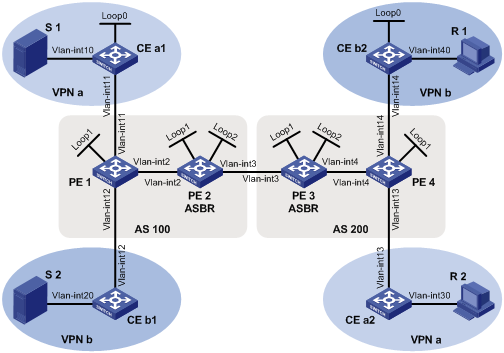
PE interfaces and VPN instances they belong to |
· PE 1: VLAN-interface 11 belongs to VPN instance b; VLAN-interface 12 belongs to VPN instance a; VLAN-interface 2 and Loopback 1 belong to the public network instance. · PE 2: VLAN-interface 2, VLAN-interface 3, Loopback 1 and Loopback 2 belong to the public network instance. · PE 3: VLAN-interface 3, VLAN-interface 4, Loopback 1 and Loopback 2 belong to the public network instance. · PE 4: VLAN-interface 13 belongs to VPN instance a; VLAN-interface 14 belongs to VPN instance b; VLAN-interface 4 and Loopback 1 belong to the public network instance. |
|
Unicast routing protocols and MPLS |
· Configure OSPF separately in AS 100 and AS 200, and configure OSPF between the PEs and CEs. · Establish BGP peer connections between PE 1, PE 2, PE 3 and PE 4 on their respective Loopback 1 interface and exchange all VPN routes between them. · Configure MPLS separately in AS 100 and AS 200. |
|
IP multicast routing |
· Enable IP multicast routing on the public network on PE 1, PE 2, PE 3 and PE 4. · Enable IP multicast routing in VPN instance a on PE 1 and PE 4. · Enable IP multicast routing in VPN instance b on PE 1 and PE 4. · Enable IP multicast routing on CE a1, CE a2, CE b1, and CE b2. |
|
IGMP |
· Run IGMPv2 on VLAN-interface 30 of CE a2. · Run IGMPv2 on VLAN-interface 40 of CE b2. |
|
PIM |
· Enable PIM-SM on all public network interfaces of PE 2 and PE 3. · Enable PIM-SM on all public and private network interfaces of PE 1 and PE 4. · Enable PIM-SM on all interfaces of CE a1, CE a2, CE b1, and CE b2. · Configure Loopback 2 of PE 2 and PE 3 as a C-BSR and a C-RP for their respective AS (to work for all multicast groups). · Configure Loopback 0 of CE a1 as a C-BSR and a C-RP for VPN a (to work for all multicast groups). · Configure Loopback 0 of CE b1 as a C-BSR and a C-RP for VPN b (to work for all multicast groups). |
|
MSDP |
· Establish an MSDP peering relationship between PE 2 and PE 3 on their respective Loopback 1. |
Figure 14 Network diagram
|
Device |
Interface |
IP address |
Device |
Interface |
IP address |
|
S 1 |
— |
10.11.5.2/24 |
R 1 |
— |
10.11.8.2/24 |
|
S 2 |
— |
10.11.6.2/24 |
R 2 |
— |
10.11.7.2/24 |
|
PE 1 |
Vlan-int2 |
10.10.1.1/24 |
PE 3 |
Vlan-int4 |
10.10.2.1/24 |
|
|
Vlan-int11 |
10.11.1.1/24 |
|
Vlan-int3 |
192.168.1.2/24 |
|
|
Vlan-int12 |
10.11.2.1/24 |
|
Loop1 |
1.1.1.3/32 |
|
|
Loop1 |
1.1.1.1/32 |
|
Loop2 |
22.22.22.22/32 |
|
PE 2 |
Vlan-int2 |
10.10.1.2/24 |
PE 4 |
Vlan-int4 |
10.10.2.2/24 |
|
|
Vlan-int3 |
192.168.1.1/24 |
|
Vlan-int13 |
10.11.3.1/24 |
|
|
Loop1 |
1.1.1.2/32 |
|
Vlan-int14 |
10.11.4.1/32 |
|
|
Loop2 |
11.11.11.11/32 |
|
Loop2 |
1.1.1.4/32 |
|
CE a1 |
Vlan-int10 |
10.11.5.1/24 |
CE b1 |
Vlan-int20 |
10.11.6.1/24 |
|
|
Vlan-int11 |
10.11.1.2/24 |
|
Vlan-int12 |
10.11.2.2/24 |
|
|
Loop0 |
2.2.2.2/32 |
CE b2 |
Vlan-int40 |
10.11.8.1/24 |
|
CE a2 |
Vlan-int30 |
10.11.7.1/24 |
|
Vlan-int14 |
10.11.4.2/24 |
|
|
Vlan-int13 |
10.11.3.2/24 |
|
Loop0 |
3.3.3.3/32 |
Configuration procedure
1. Configure PE 1:
# Configure a Router ID, enable IP multicast routing on the public network, configure an MPLS LSR ID, and enable the LDP capability.
<PE1> system-view
[PE1] router id 1.1.1.1
[PE1] multicast routing-enable
[PE1] mpls lsr-id 1.1.1.1
[PE1] mpls
[PE1-mpls] quit
[PE1] mpls ldp
[PE1-mpls-ldp] quit
# Create VPN instance a, configure an RD for it, and create an ingress route and an egress route for it; enable IP multicast routing in VPN instance a, configure a share-group address, associate an MTI with the VPN instance, and define the switch-group-pool address range.
[PE1] ip vpn-instance a
[PE1-vpn-instance-a] route-distinguisher 100:1
[PE1-vpn-instance-a] vpn-target 100:1 export-extcommunity
[PE1-vpn-instance-a] vpn-target 100:1 import-extcommunity
[PE1-vpn-instance-a] multicast routing-enable
[PE1-vpn-instance-a] multicast-domain share-group 239.1.1.1 binding mtunnel 0
[PE1-vpn-instance-a] multicast-domain switch-group-pool 225.1.1.0 28
[PE1-vpn-instance-a] quit
# Create VPN instance b, configure an RD for it, and create an ingress route and an egress route for it; enable IP multicast routing in VPN instance b, configure a share-group address, associate an MTI with the VPN instance, and define the switch-group-pool address range.
[PE1] ip vpn-instance b
[PE1-vpn-instance-b] route-distinguisher 200:1
[PE1-vpn-instance-b] vpn-target 200:1 export-extcommunity
[PE1-vpn-instance-b] vpn-target 200:1 import-extcommunity
[PE1-vpn-instance-b] multicast routing-enable
[PE1-vpn-instance-b] multicast-domain share-group 239.4.4.4 binding mtunnel 1
[PE1-vpn-instance-b] multicast-domain switch-group-pool 225.4.4.0 28
[PE1-vpn-instance-b] quit
# Configure an IP address, and enable PIM-SM and LDP capability on the public network interface VLAN-interface 2.
[PE1] interface vlan-interface 2
[PE1-Vlan-interface2] ip address 10.10.1.1 24
[PE1-Vlan-interface2] pim sm
[PE1-Vlan-interface2] mpls
[PE1-Vlan-interface2] mpls ldp
[PE1-Vlan-interface2] quit
# Bind VLAN-interface 11 with VPN instance a, configure an IP address and enable PIM-SM on the interface.
[PE1] interface vlan-interface 11
[PE1-Vlan-interface11] ip binding vpn-instance a
[PE1-Vlan-interface11] ip address 10.11.1.1 24
[PE1-Vlan-interface11] pim sm
[PE1-Vlan-interface11] quit
# Bind VLAN-interface 12 with VPN instance b, configure an IP address and enable PIM-SM on the interface.
[PE1] interface vlan-interface 12
[PE1-Vlan-interface12] ip binding vpn-instance b
[PE1-Vlan-interface12] ip address 10.11.2.1 24
[PE1-Vlan-interface12] pim sm
[PE1-Vlan-interface12] quit
# Configure an IP address for Loopback 1, and enable PIM-SM.
[PE1] interface loopback 1
[PE1-LoopBack1] ip address 1.1.1.1 32
[PE1-LoopBack1] pim sm
[PE1-LoopBack1] quit
# Configure BGP.
[PE1] bgp 100
[PE1-bgp] group pe1-pe2 internal
[PE1-bgp] peer pe1-pe2 label-route-capability
[PE1-bgp] peer pe1-pe2 connect-interface loopback 1
[PE1-bgp] peer 1.1.1.2 group pe1-pe2
[PE1-bgp] group pe1-pe4 external
[PE1-bgp] peer pe1-pe4 as-number 200
[PE1-bgp] peer pe1-pe4 ebgp-max-hop 255
[PE1-bgp] peer 1.1.1.4 group pe1-pe4
[PE1-bgp] peer pe1-pe2 connect-interface loopback 1
[PE1–bgp] ipv4-family vpn-instance a
[PE1-bgp-a] import-route ospf 2
[PE1-bgp-a] import-route direct
[PE1-bgp-a] quit
[PE1–bgp] ipv4-family vpn-instance b
[PE1-bgp-b] import-route ospf 3
[PE1-bgp-b] import-route direct
[PE1-bgp-b] quit
[PE1–bgp] ipv4-family vpnv4
[PE1–bgp-af-vpnv4] peer 1.1.1.4 enable
[PE1–bgp-af-vpnv4] quit
[PE1–bgp] quit
With BGP peers configured on PE 1, the interfaces MTI 0 and MTI 1 will automatically obtain IP addresses, which are the loopback interface addresses specified in the BGP peer configuration. The PIM mode running on MTI 0 is the same as on the interfaces in VPN instance a, and the PIM mode running on MTI 1 is the same as on the interfaces in VPN instance b.
# Configure OSPF.
[PE1] ospf 1
[PE1-ospf-1] area 0.0.0.0
[PE1-ospf-1-area-0.0.0.0] network 1.1.1.1 0.0.0.0
[PE1-ospf-1-area-0.0.0.0] network 10.10.0.0 0.0.255.255
[PE1-ospf-1-area-0.0.0.0] quit
[PE1-ospf-1] quit
[PE1] ospf 2 vpn-instance a
[PE1-ospf-2] import-route bgp
[PE1-ospf-2] area 0.0.0.0
[PE1-ospf-2-area-0.0.0.0] network 10.11.0.0 0.0.255.255
[PE1-ospf-2-area-0.0.0.0] quit
[PE1-ospf-2] quit
[PE1] ospf 3 vpn-instance b
[PE1-ospf-3] import-route bgp
[PE1-ospf-3] area 0.0.0.0
[PE1-ospf-3-area-0.0.0.0] network 10.11.0.0 0.0.255.255
[PE1-ospf-3-area-0.0.0.0] quit
[PE1-ospf-3] quit
2. Configure PE 2:
# Configure a Router ID, enable IP multicast routing on the public network, configure an MPLS LSR ID, and enable the LDP capability.
<PE2> system-view
[PE2] router id 1.1.1.2
[PE2] multicast routing-enable
[PE2] mpls lsr-id 1.1.1.2
[PE2] mpls
[PE2-mpls] quit
[PE2] mpls ldp
[PE2-mpls-ldp] quit
# Configure an IP address, and enable PIM-SM and LDP capability on the public network interface VLAN-interface 2.
[PE2] interface vlan-interface 2
[PE2-Vlan-interface2] ip address 10.10.1.2 24
[PE2-Vlan-interface2] pim sm
[PE2-Vlan-interface2] mpls
[PE2-Vlan-interface2] mpls ldp
[PE2-Vlan-interface2] quit
# Configure an IP address, and enable PIM-SM and MPLS capability on the public network interface VLAN-interface 3.
[PE2] interface vlan-interface 3
[PE2-Vlan-interface3] ip address 192.168.1.1 24
[PE2-Vlan-interface3] pim sm
[PE2-Vlan-interface3] mpls
[PE2-Vlan-interface3] quit
# Configure an IP address for Loopback 1, and enable PIM-SM.
[PE2] interface loopback 1
[PE2-LoopBack1] ip address 1.1.1.2 32
[PE2-LoopBack1] pim sm
[PE2-LoopBack1] quit
# Configure an IP address for Loopback 2, and enable PIM-SM.
[PE2] interface loopback 2
[PE2-LoopBack2] ip address 11.11.11.11 32
[PE2-LoopBack2] pim sm
[PE2-LoopBack2] quit
# Configure Loopback 2 as a C-BSR and a C-RP for the public network instance.
[PE2] pim
[PE2-pim] c-bsr loopback 2
[PE2-pim] c-rp loopback 2
[PE2-pim] quit
# Configure a BSR message boundary.
[PE2] interface vlan-interface 3
[PE2-Vlan-interface3] pim bsr-boundary
[PE2-Vlan-interface3] quit
# Establish an MSDP peering relationship.
[PE2] msdp
[PE2-msdp] encap-data-enable
[PE2-msdp] peer 1.1.1.3 connect-interface loopback 1
# Configure a static route.
[PE2] ip route-static 1.1.1.3 32 vlan-interface 3 192.168.1.2
# Configure BGP.
[PE2] bgp 100
[PE2-bgp] import-route ospf 1
[PE2-bgp] group pe2-pe1 internal
[PE2-bgp] peer pe2-pe1 route-policy map2 export
[PE2-bgp] peer pe2-pe1 label-route-capability
[PE2-bgp] peer pe2-pe1 connect-interface loopback 1
[PE2-bgp] peer 1.1.1.1 group pe2-pe1
[PE2-bgp] group pe2-pe3 external
[PE2-bgp] peer pe2-pe3 as-number 200
[PE2-bgp] peer pe2-pe3 route-policy map1 export
[PE2-bgp] peer pe2-pe3 label-route-capability
[PE2-bgp] peer pe2-pe3 connect-interface loopback 1
[PE2-bgp] peer 1.1.1.3 group pe2-pe3
[PE2–bgp] quit
# Configure OSPF.
[PE2] ospf 1
[PE2-ospf-1] area 0.0.0.0
[PE2-ospf-1-area-0.0.0.0] network 1.1.1.2 0.0.0.0
[PE2-ospf-1-area-0.0.0.0] network 11.11.11.11 0.0.0.0
[PE2-ospf-1-area-0.0.0.0] network 10.10.0.0 0.0.255.255
[PE2-ospf-1-area-0.0.0.0] quit
[PE2-ospf-1] quit
# Configure a routing policy.
[PE2] route-policy map1 permit node 10
[PE2-route-policy] apply mpls-label
[PE2-route-policy] quit
[PE2] route-policy map2 permit node 10
[PE2-route-policy] if-match mpls-label
[PE2-route-policy] apply mpls-label
[PE2-route-policy] quit
3. Configure PE 3:
# Configure a Router ID, enable IP multicast routing on the public network, configure an MPLS LSR ID, and enable the LDP capability.
<PE3> system-view
[PE3] router id 1.1.1.3
[PE3] multicast routing-enable
[PE3] mpls lsr-id 1.1.1.3
[PE3] mpls
[PE3-mpls] quit
[PE3] mpls ldp
[PE3-mpls-ldp] quit
# Configure an IP address, and enable PIM-SM and LDP capability on the public network interface VLAN-interface 4.
[PE3] interface vlan-interface 4
[PE3-Vlan-interface4] ip address 10.10.2.1 24
[PE3-Vlan-interface4] pim sm
[PE3-Vlan-interface4] mpls
[PE3-Vlan-interface4] mpls ldp
[PE3-Vlan-interface4] quit
# Configure an IP address, and enable PIM-SM and MPLS capability on the public network interface VLAN-interface 3.
[PE3] interface vlan-interface 3
[PE3-Vlan-interface3] ip address 192.168.1.2 24
[PE3-Vlan-interface3] pim sm
[PE3-Vlan-interface3] mpls
[PE3-Vlan-interface3] quit
# Configure an IP address for Loopback 1, and enable PIM-SM.
[PE3] interface loopback 1
[PE3-LoopBack1] ip address 1.1.1.3 32
[PE3-LoopBack1] pim sm
[PE3-LoopBack1] quit
# Configure an IP address for Loopback 2, and enable PIM-SM.
[PE3] interface loopback 2
[PE3-LoopBack2] ip address 22.22.22.22 32
[PE3-LoopBack2] pim sm
[PE3-LoopBack2] quit
# Configure Loopback 2 as a C-BSR and a C-RP for the public network instance.
[PE3] pim
[PE3-pim] c-bsr loopback 2
[PE3-pim] c-rp loopback 2
[PE3-pim] quit
# Configure a BSR message boundary.
[PE3] interface vlan-interface 3
[PE3-Vlan-interface3] pim bsr-boundary
[PE3-Vlan-interface3] quit
# Establish an MSDP peering relationship.
[PE3] msdp
[PE3-msdp] encap-data-enable
[PE3-msdp] peer 1.1.1.2 connect-interface loopback 1
# Configure a static route.
[PE3] ip route-static 1.1.1.2 32 vlan-interface 3 192.168.1.1
# Configure BGP.
[PE3] bgp 200
[PE3-bgp] import-route ospf 1
[PE3-bgp] group pe3-pe4 internal
[PE3-bgp] peer pe3-pe4 route-policy map2 export
[PE3-bgp] peer pe3-pe4 label-route-capability
[PE3-bgp] peer pe3-pe4 connect-interface loopback 1
[PE3-bgp] peer 1.1.1.4 group pe3-pe4
[PE3-bgp] group pe3-pe2 external
[PE3-bgp] peer pe3-pe2 as-number 100
[PE3-bgp] peer pe3-pe2 route-policy map1 export
[PE3-bgp] peer pe3-pe2 label-route-capability
[PE3-bgp] peer pe3-pe2 connect-interface loopback 1
[PE3-bgp] peer 1.1.1.2 group pe3-pe2
[PE3–bgp] quit
# Configure OSPF.
[PE3] ospf 1
[PE3-ospf-1] area 0.0.0.0
[PE3-ospf-1-area-0.0.0.0] network 1.1.1.3 0.0.0.0
[PE3-ospf-1-area-0.0.0.0] network 22.22.22.22 0.0.0.0
[PE3-ospf-1-area-0.0.0.0] network 10.10.0.0 0.0.255.255
[PE3-ospf-1-area-0.0.0.0] quit
[PE3-ospf-1] quit
# Configure a routing policy.
[PE3] route-policy map1 permit node 10
[PE3-route-policy] apply mpls-label
[PE3-route-policy] quit
[PE3] route-policy map2 permit node 10
[PE3-route-policy] if-match mpls-label
[PE3-route-policy] apply mpls-label
[PE3-route-policy] quit
4. Configure PE 4:
# Configure a Router ID, enable IP multicast routing on the public network, configure an MPLS LSR ID, and enable the LDP capability.
<PE4> system-view
[PE4] router id 1.1.1.4
[PE4] multicast routing-enable
[PE4] mpls lsr-id 1.1.1.4
[PE4] mpls
[PE4-mpls] quit
[PE4] mpls ldp
[PE4-mpls-ldp] quit
# Create VPN instance a, configure an RD for it, and create an ingress route and an egress route for it; enable IP multicast routing in VPN instance a, configure a share-group address, associate an MTI with the VPN instance, and define the switch-group-pool address range.
[PE4] ip vpn-instance a
[PE4-vpn-instance-a] route-distinguisher 100:1
[PE4-vpn-instance-a] vpn-target 100:1 export-extcommunity
[PE4-vpn-instance-a] vpn-target 100:1 import-extcommunity
[PE4-vpn-instance-a] multicast routing-enable
[PE4-vpn-instance-a] multicast-domain share-group 239.1.1.1 binding mtunnel 0
[PE4-vpn-instance-a] multicast-domain switch-group-pool 225.1.1.0 28
[PE4-vpn-instance-a] quit
# Create VPN instance b, configure an RD for it, and create an ingress route and an egress route for it; enable IP multicast routing in VPN instance b, configure a share-group address, associate an MTI with the VPN instance, and define the switch-group-pool address range.
[PE4] ip vpn-instance b
[PE4-vpn-instance-b] route-distinguisher 200:1
[PE4-vpn-instance-b] vpn-target 200:1 export-extcommunity
[PE4-vpn-instance-b] vpn-target 200:1 import-extcommunity
[PE4-vpn-instance-b] multicast routing-enable
[PE4-vpn-instance-b] multicast-domain share-group 239.4.4.4 binding mtunnel 1
[PE4-vpn-instance-b] multicast-domain switch-group-pool 225.4.4.0 28
[PE4-vpn-instance-b] quit
# Configure an IP address, and enable PIM-SM and LDP capability on the public network interface VLAN-interface 4.
[PE4] interface vlan-interface 4
[PE4-Vlan-interface4] ip address 10.10.2.2 24
[PE4-Vlan-interface4] pim sm
[PE4-Vlan-interface4] mpls
[PE4-Vlan-interface4] mpls ldp
[PE4-Vlan-interface4] quit
# Bind VLAN-interface 13 with VPN instance a, configure an IP address and enable PIM-SM on the interface.
[PE4] interface vlan-interface 13
[PE4-Vlan-interface13] ip binding vpn-instance a
[PE4-Vlan-interface13] ip address 10.11.3.1 24
[PE4-Vlan-interface13] pim sm
[PE4-Vlan-interface13] quit
# Bind VLAN-interface 14 with VPN instance b, configure an IP address and enable PIM-SM on the interface.
[PE4] interface vlan-interface 14
[PE4-Vlan-interface14] ip binding vpn-instance b
[PE4-Vlan-interface14] ip address 10.11.4.1 24
[PE4-Vlan-interface14] pim sm
[PE4-Vlan-interface14] quit
# Configure an IP address for Loopback 1, and enable PIM-SM.
[PE4] interface loopback 1
[PE4-LoopBack1] ip address 1.1.1.4 32
[PE4-LoopBack1] pim sm
[PE4-LoopBack1] quit
# Configure BGP.
[PE4] bgp 200
[PE4-bgp] group pe4-pe3 internal
[PE4-bgp] peer pe4-pe3 label-route-capability
[PE4-bgp] peer pe4-pe3 connect-interface loopback 1
[PE4-bgp] peer 1.1.1.3 group pe4-pe3
[PE4-bgp] group pe4-pe1 external
[PE4-bgp] peer pe4-pe1 as-number 100
[PE4-bgp] peer pe4-pe1 ebgp-max-hop 255
[PE4-bgp] peer 1.1.1.1 group pe4-pe1
[PE4-bgp] peer pe4-pe1 connect-interface loopback 1
[PE4–bgp] ipv4-family vpn-instance a
[PE4-bgp-a] import-route ospf 2
[PE4-bgp-a] import-route direct
[PE4-bgp-a] quit
[PE4–bgp] ipv4-family vpn-instance b
[PE4-bgp-b] import-route ospf 3
[PE4-bgp-b] import-route direct
[PE4-bgp-b] quit
[PE4–bgp] ipv4-family vpnv4
[PE4–bgp-af-vpnv4] peer 1.1.1.1 enable
[PE4–bgp-af-vpnv4] quit
[PE4–bgp] quit
With BGP peers configured on PE 4, the interfaces MTI 0 and MTI 1 will automatically obtain IP addresses, which are the loopback interface addresses specified in the BGP peer configuration. The PIM mode running on MTI 0 is the same as on the interfaces in VPN instance a, and the PIM mode running on MTI 1 is the same as on the interfaces in VPN instance b.
# Configure OSPF.
[PE4] ospf 1
[PE4-ospf-1] area 0.0.0.0
[PE4-ospf-1-area-0.0.0.0] network 1.1.1.4 0.0.0.0
[PE4-ospf-1-area-0.0.0.0] network 10.10.0.0 0.0.255.255
[PE4-ospf-1-area-0.0.0.0] quit
[PE4-ospf-1] quit
[PE4] ospf 2 vpn-instance a
[PE4-ospf-2] import-route bgp
[PE4-ospf-2] area 0.0.0.0
[PE4-ospf-2-area-0.0.0.0] network 10.11.0.0 0.0.255.255
[PE4-ospf-2-area-0.0.0.0] quit
[PE4-ospf-2] quit
[PE4] ospf 3 vpn-instance b
[PE4-ospf-3] import-route bgp
[PE4-ospf-3] area 0.0.0.0
[PE4-ospf-3-area-0.0.0.0] network 10.11.0.0 0.0.255.255
[PE4-ospf-3-area-0.0.0.0] quit
[PE4-ospf-3] quit
5. Configure CE a1:
# Enable IP multicast routing.
<CEa1> system-view
[CEa1] multicast routing-enable
# Configure an IP address for VLAN-interface 10 and enable PIM-SM on the interface.
[CEa1] interface vlan-interface 10
[CEa1-Vlan-interface10] ip address 10.11.5.1 24
[CEa1-Vlan-interface10] pim sm
[CEa1-Vlan-interface10] quit
# Configure an IP address for VLAN-interface 11 and enable PIM-SM on the interface.
[CEa1] interface vlan-interface 11
[CEa1-Vlan-interface11] ip address 10.11.1.2 24
[CEa1-Vlan-interface11] pim sm
[CEa1-Vlan-interface11] quit
# Configure an IP address for Loopback 1, and enable PIM-SM.
[CEa1] interface loopback 1
[CEa1-LoopBack1] ip address 2.2.2.2 32
[CEa1-LoopBack1] pim sm
[CEa1-LoopBack1] quit
# Configure Loopback 1 as a C-BSR and a C-RP for VPN a.
[CEa1] pim
[CEa1-pim] c-bsr loopback 1
[CEa1-pim] c-rp loopback 1
[CEa1-pim] quit
# Configure OSPF.
[CEa1] ospf 1
[CEa1-ospf-1] area 0.0.0.0
[CEa1-ospf-1-area-0.0.0.0] network 2.2.2.2 0.0.0.0
[CEa1-ospf-1-area-0.0.0.0] network 10.11.0.0 0.0.255.255
[CEa1-ospf-1-area-0.0.0.0] quit
[CEa1-ospf-1] quit
6. Configure CE b1:
# Enable IP multicast routing.
<CEb1> system-view
[CEb1] multicast routing-enable
# Configure an IP address for VLAN-interface 20 and enable PIM-SM on the interface.
[CEb1] interface vlan-interface 20
[CEb1-Vlan-interface20] ip address 10.11.6.1 24
[CEb1-Vlan-interface20] pim sm
[CEb1-Vlan-interface20] quit
# Configure an IP address for VLAN-interface 12 and enable PIM-SM on the interface.
[CEb1] interface vlan-interface 12
[CEb1-Vlan-interface12] ip address 10.11.2.2 24
[CEb1-Vlan-interface12] pim sm
[CEb1-Vlan-interface12] quit
# Configure OSPF.
[CEb1] ospf 1
[CEb1-ospf-1] area 0.0.0.0
[CEb1-ospf-1-area-0.0.0.0] network 10.11.0.0 0.0.255.255
[CEb1-ospf-1-area-0.0.0.0] quit
[CEb1-ospf-1] quit
7. Configure CE a2:
# Enable IP multicast routing.
<CEa2> system-view
[CEa2] multicast routing-enable
# Configure an IP address for VLAN-interface 30 and enable IGMP and PIM-SM on the interface.
[CEa2] interface vlan-interface 30
[CEa2-Vlan-interface30] ip address 10.11.7.1 24
[CEa2-Vlan-interface30] igmp enable
[CEa2-Vlan-interface30] pim sm
[CEa2-Vlan-interface30] quit
# Configure an IP address for VLAN-interface 13 and enable PIM-SM on the interface.
[CEa2] interface vlan-interface 13
[CEa2-Vlan-interface13] ip address 10.11.3.2 24
[CEa2-Vlan-interface13] pim sm
[CEa2-Vlan-interface13] quit
# Configure OSPF.
[CEa2] ospf 1
[CEa2-ospf-1] area 0.0.0.0
[CEa2-ospf-1-area-0.0.0.0] network 10.11.0.0 0.0.255.255
[CEa2-ospf-1-area-0.0.0.0] quit
[CEa2-ospf-1] quit
8. Configure CE b2:
# Enable IP multicast routing.
<CEb2> system-view
[CEb2] multicast routing-enable
# Configure an IP address for VLAN-interface 40 and enable IGMP and PIM-SM on the interface.
[CEb2] interface vlan-interface 40
[CEb2-Vlan-interface40] ip address 10.11.8.1 24
[CEb2-Vlan-interface40] igmp enable
[CEb2-Vlan-interface40] pim sm
[CEb2-Vlan-interface40] quit
# Configure an IP address for VLAN-interface 14 and enable PIM-SM on the interface.
[CEb2] interface vlan-interface 14
[CEb2-Vlan-interface14] ip address 10.11.4.2 24
[CEb2-Vlan-interface14] pim sm
[CEb2-Vlan-interface14] quit
# Configure an IP address for Loopback 1, and enable PIM-SM.
[CEb2] interface loopback 1
[CEb2-LoopBack1] ip address 3.3.3.3 32
[CEb2-LoopBack1] pim sm
[CEb2-LoopBack1] quit
# Configure Loopback 1 as a C-BSR and a C-RP for VPN b.
[CEb2] pim
[CEb2-pim] c-bsr loopback 1
[CEb2-pim] c-rp loopback 1
[CEb2-pim] quit
# Configure OSPF.
[CEb2] ospf 1
[CEb2-ospf-1] area 0.0.0.0
[CEb2-ospf-1-area-0.0.0.0] network 3.3.3.3 0.0.0.0
[CEb2-ospf-1-area-0.0.0.0] network 10.11.0.0 0.0.255.255
[CEb2-ospf-1-area-0.0.0.0] quit
[CEb2-ospf-1] quit
9. Verify the configuration
# Display the local share-group information of VPN instance a on PE 1.
<PE1> display multicast-domain vpn-instance a share-group local
MD local share-group information for VPN-Instance: a
Share-group: 239.1.1.1
MTunnel address: 1.1.1.1
# Display the local share-group information of VPN instance b on PE 1.
<PE1> display multicast-domain vpn-instance b share-group local
MD local share-group information for VPN-Instance: b
Share-group: 239.4.4.4
MTunnel address: 1.1.1.1
# Display the local share-group information of VPN instance a on PE 4.
<PE4> display multicast-domain vpn-instance a share-group local
MD local share-group information for VPN-Instance: a
Share-group: 239.1.1.1
MTunnel address: 1.1.1.4
# Display the local share-group information of VPN instance b on PE 4.
<PE4> display multicast-domain vpn-instance b share-group local
MD local share-group information for VPN-Instance: b
Share-group: 239.4.4.4
MTunnel address: 1.1.1.4
Troubleshooting MD-VPN
A share-MDT cannot be established
Symptom
A share-MDT cannot be established. PIM adjacencies cannot be established between the same VPN instance’s interfaces on different PE devices.
Analysis
· On different PE devices, the same share-group must be configured for the same VPN instance. A share-group address uniquely identifies a share-MDT. If different share-group addresses have been configured for a VPN instance on different PE devices, a share-MDT cannot be established for that VPN instance on different PE devices.
· The same PIM mode must run on all the interfaces of the same VPN instance on different PE devices and on all the interfaces of the P router. Otherwise, a share-MDT cannot be correctly built for the VPN instance and PIM adjacencies cannot be established between the VPN instance on the local PE device and the same VPN instance on the remote PE device.
· BGP and unicast route configurations are prerequisites for the MTI interface to obtain an IP address automatically, and PIM is enabled on at least one interface of the VPN instance so that PIM can be enabled on the MTI interface. PIM adjacencies can be established between the same VPN instance on different PE devices only after the MTI interface obtains an IP address and gets PIM enabled.
Solution
1. Check the share-group address: Use the display multicast-domain vpn-instance share-group command to verify that the same share-group address has been configured for the same VPN instance on different PE devices.
2. Check the running PIM mode: Use the display pim interface command to verify that PIM is enabled on at least one interface of the same VPN on different PE devices and the same PIM mode is running on all the interfaces of the same VPN instance on different PE devices and on all the interfaces of the P router.
3. Check unicast routes. Use the display ip routing-table command to verify that a unicast route exists from the VPN instance on the local PE device to the same VPN instance on each remote PE device.
4. Check BGP peer configuration: Use the display bgp peer command to verify that the BGP peer connections have been correctly configured.
An MVRF cannot be created
Symptom
A VPN instance cannot create an MVRF correctly.
Analysis
· If PIM-SM is running in the VPN instance, the BSR information for the VPN instance is required. Otherwise, the VPN instance’s MVRF cannot be correctly established.
· If PIM-SM is running in the VPN instance, the RP information for the VPN instance is required. If a unicast route to the RP is not available, this means that a PIM adjacency has not been correctly established between the public network and the VPN instance, and thus VPN instance cannot correctly establish its MVRF.
· The customer DR must have a route to the VPN RP.
Solution
1. Use the display pim bsr-info command to verify that the BSR information exists on the public network and VPN instance. If not, check whether a unicast route exists to the BSR.
2. Use the display pim rp-info command to view the RP information. If no RP information is available, check whether a unicast route exists to the RP. Use the display pim neighbor command to check whether the PIM adjacencies have correctly established in the public network and the VPN.
3. Use the ping command to check the connectivity between the VPN DR and the VPN RP.