- Table of Contents
-
- 08-IP Multicast Configuration Guide
- 00-Preface
- 01-Multicast Overview
- 02-IGMP Snooping Configuration
- 03-PIM Snooping Configuration
- 04-Multicast VLAN Configuration
- 05-Multicast Routing and Forwarding Configuration
- 06-IGMP Configuration
- 07-PIM Configuration
- 08-MSDP Configuration
- 09-MBGP Configuration
- 10-Multicast VPN Configuration
- 11-MLD Snooping Configuration
- 12-IPv6 PIM Snooping Configuration
- 13-IPv6 Multicast VLAN Configuration
- 14-IPv6 Multicast Routing and Forwarding Configuration
- 15-MLD Configuration
- 16-IPv6 PIM Configuration
- 17-IPv6 MBGP Configuration
- Related Documents
-
| Title | Size | Download |
|---|---|---|
| 08-MSDP Configuration | 540.51 KB |
Contents
Configuring basic MSDP functions
Creating an MSDP peer connection
Configuring an MSDP peer connection
Configuring MSDP peer description
Configuring an MSDP mesh group
Configuring MSDP peer connection control
Configuring SA messages related parameters
Configuring SA message content
Configuring SA request messages
Configuring SA message filtering rules
Configuring the SA cache mechanism
Displaying and maintaining MSDP
PIM-SM Inter-domain multicast configuration
Inter-AS multicast configuration by leveraging static RPF peers
SA message filtering configuration
No SA entries in the devices’s SA cache
Inter-RP communication faults in anycast RP application
|
|
NOTE: · The term router in this document refers to both routers and Layer 3 switches. · For more information about the concepts of designated router (DR), bootstrap router (BSR), candidate-BSR (C-BSR), rendezvous point (RP), candidate-RP (C-RP), shortest path tree (SPT) and rendezvous point tree (RPT) mentioned in this document, see the chapter “Configuring PIM.” |
MSDP overview
Multicast source discovery protocol (MSDP) is an inter-domain multicast solution that addresses the interconnection of protocol independent multicast sparse mode (PIM-SM) domains. It discovers multicast source information in other PIM-SM domains.
In the basic PIM-SM mode, a multicast source registers only with the RP in the local PIM-SM domain, and the multicast source information about a domain is isolated from that of another domain. As a result, the RP obtains the source information only within the local domain and a multicast distribution tree is built only within the local domain to deliver multicast data from a local multicast source to local receivers. MSDP enables the RPs of different PIM-SM domains to share their multicast source information, so that the local RP can join multicast sources in other domains and multicast data can be transmitted among different domains.
With MSDP peer relationships established between appropriate routers in the network, the RPs of different PIM-SM domains are interconnected with one another. These MSDP peers exchange source active (SA) messages, so that the multicast source information is shared among these different domains.
|
|
NOTE: · MSDP is applicable only if the intra-domain multicast protocol is PIM-SM. · MSDP is meaningful only for the any-source multicast (ASM) model. |
How MSDP works
MSDP peers
Configuring one or more pairs of MSDP peers in the network forms an MSDP interconnection map, where the RPs of different PIM-SM domains are interconnected in series. An SA message sent by an RP and relayed by these MSDP peers can be delivered to all other RPs.
Figure 1 Where MSDP peers are in the network
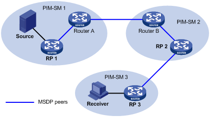
As shown in Figure 1, an MSDP peer can be created on any PIM-SM router. MSDP peers created on PIM-SM routers that assume different roles function differently.
1. MSDP peers on RPs include the following types:
¡ Source-side MSDP peer—The MSDP peer nearest to the multicast source (Source), typically the source-side RP, like RP 1. The source-side RP creates SA messages and sends the messages to its remote MSDP peer to notify the MSDP peer of the locally registered multicast source information. A source-side MSDP peer must be created on the source-side RP. Otherwise it will not be able to advertise the multicast source information out of the PIM-SM domain.
¡ Receiver-side MSDP peer—The MSDP peer nearest to the receivers, typically the receiver-side RP, like RP 3. After receiving an SA message, the receiver-side MSDP peer resolves the multicast source information carried in the message and joins the SPT rooted at the source across the PIM-SM domain. When multicast data from the multicast source arrives, the receiver-side MSDP peer forwards the data to the receivers along the RPT.
¡ Intermediate MSDP peer—An MSDP peer with multicast remote MSDP peers, like RP 2. An intermediate MSDP peer forwards SA messages received from one remote MSDP peer to other remote MSDP peers, functioning as a relay of multicast source information.
2. MSDP peers created on common PIM-SM routers (other than RPs)
Router A and Router B are MSDP peers on common multicast routers. Such MSDP peers just forward received SA messages.
|
|
NOTE: In a PIM-SM network running the BSR mechanism, the RP is dynamically elected from C-RPs. To enhance network robustness, a PIM-SM network typically has more than one C-RP. As the RP election result is unpredictable, MSDP peering relationships must be built among all C-RPs so that the winner C-RP is always on the “MSDP interconnection map”, and loser C-RPs will assume the role of common PIM-SM routers on the “MSDP interconnection map”. |
Inter-domain multicast delivery through MSDP
As shown in Figure 2, an active source (Source) exists in the domain PIM-SM 1, and RP 1 has learned the existence of Source through multicast source registration. If RPs in PIM-SM 2 and PIM-SM 3 also seek the specific location of Source so that receiver hosts can receive multicast traffic that originated from it, MSDP peering relationships must be established between RP 1 and RP 3 and between RP 3 and RP 2 respectively.
Figure 2 Inter-domain multicast delivery through MSDP
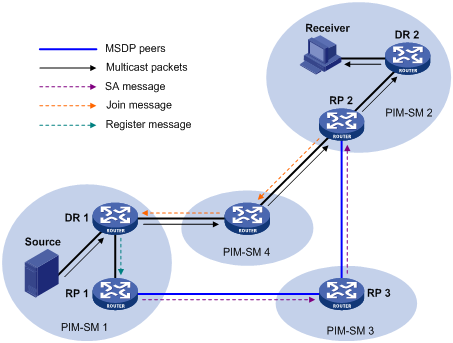
The process of implementing PIM-SM inter-domain multicast delivery by leveraging MSDP peers is as follows:
1. When the multicast source in PIM-SM 1 sends the first multicast packet to multicast group G, DR 1 encapsulates the multicast data within a register message and sends the register message to RP 1. Then, RP 1identifies the information related to the multicast source.
2. As the source-side RP, RP 1 creates SA messages and periodically sends the SA messages to its MSDP peer. An SA message contains the source address (S), the multicast group address (G), and the address of the RP that has created this SA message (namely RP 1).
3. On MSDP peers, each SA message undergoes a reverse path forwarding (RPF) check and multicast policy–based filtering, so that only SA messages that have arrived along the correct path and passed the filtering are received and forwarded. This avoids delivery loops of SA messages. In addition, you can configure MSDP peers into an MSDP mesh group so as to avoid flooding of SA messages between MSDP peers.
4. SA messages are forwarded from one MSDP peer to another, and finally the information about the multicast source traverses all PIM-SM domains with MSDP peers (PIM-SM 2 and PIM-SM 3 in this example).
5. After receiving the SA message that RP 1created, RP 2 in PIM-SM 2 determines whether any receivers for the multicast group exist in the domain.
¡ If so, the RPT for the multicast group G is maintained between RP 2 and the receivers. RP 2 creates an (S, G) entry, and sends an (S, G) join message hop by hop toward DR 1 at the multicast source side, so that it can directly join the SPT rooted at the source over other PIM-SM domains. Then, the multicast data can flow along the SPT to RP 2 and RP 2 can forward the data to the receivers along the RPT. After receiving the multicast traffic, the DR at the receiver side (DR 2) determines whether to initiate an RPT-to-SPT switchover process.
¡ If no receivers for the group exist in the domain, RP 2 neither creates an (S, G) entry nor joins the SPT rooted at the source.
|
|
NOTE: · An MSDP mesh group refers to a group of MSDP peers that have MSDP peering relationships among one another and share the same group name. · When using MSDP for inter-domain multicasting, once an RP receives information form a multicast source, it no longer relies on RPs in other PIM-SM domains. The receivers can override the RPs in other domains and directly join the multicast source-based SPT. |
RPF check rules for SA messages
As shown in Figure 3, the autonomous systems in the network are AS 1 through AS 5, with IGP enabled on routers within each AS and BGP or MBGP as the interoperation protocol among different ASs. Each AS contains at least one PIM-SM domain, and each PIM-SM domain contains one ore more RPs. MSDP peering relationships have been established among different RPs. RP 3, RP 4, and RP 5 are in an MSDP mesh group. On RP 7, RP 6 is configured as its static RPF peer.
|
|
NOTE: When the switch receives an SA message from a static RPF peer, it accepts the SA message and forwards it to other peers without performing an RPF check. |
Figure 3 Diagram for RPF check for SA messages
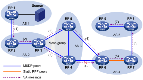
As illustrated in Figure 3, these MSDP peers dispose of SA messages according to the following RPF check rules:
1. When RP 2 receives an SA message from RP 1—Because the source-side RP address carried in the SA message is the same as the MSDP peer address, which means that the MSDP peer where the SA is from is the RP that has created the SA message, RP 2 accepts the SA message and forwards it to its other MSDP peer (RP 3).
2. When RP 3 receives the SA message from RP 2—Because the SA message is from an MSDP peer (RP 2) in the same AS, and the MSDP peer is the next hop on the optimal path to the source-side RP, RP 3 accepts the message and forwards it to other peers (RP 4 and RP 5).
3. When RP 4 and RP 5 receive the SA message from RP 3—Because the SA message is from an MSDP peer (RP 3) in the same mesh group, RP 4 and RP 5 both accept the SA message, but they do not forward the message to other members in the mesh group. Instead, they forward it to other MSDP peers (RP 6 in this example) out of the mesh group.
4. When RP 6 receives the SA messages from RP 4 and RP 5 (suppose RP 5 has a higher IP address)—Although RP 4 and RP 5 are in the same AS (AS 3) and both are MSDP peers of RP 6, because RP 5 has a higher IP address, RP 6 accepts only the SA message from RP 5.
5. When RP 7 receives the SA message from RP 6—Because the SA message is from a static RPF peer (RP 6), RP 7 accepts the SA message and forwards it to other peer (RP 8).
6. When RP 8 receives the SA message from RP 7—A BGP or MBGP route exists between two MSDP peers in different ASs. Because the SA message is from an MSDP peer (RP 7) in a different AS, and the MSDP peer is the next hop on the BGP or MBGP route to the source-side RP, RP 8 accepts the message and forwards it to its other peer (RP 9).
7. When RP 9 receives the SA message from RP 8—Because RP 9 has only one MSDP peer, RP 9 accepts the SA message.
SA messages from paths other than those described previously will not be accepted or forwarded by MSDP peers.
Intra-domain Anycast RP through MSDP
Anycast RP refers to an application that enables load balancing and redundancy backup between two or more RPs within a PIM-SM domain by configuring the same IP address for, and establishing MSDP peering relationships between, these RPs.
As shown in Figure 4, within a PIM-SM domain, a multicast source sends multicast data to multicast group G, and Receiver is a member of the multicast group. To implement Anycast RP, configure the same IP address (known as Anycast RP address, typically a private address) on Router A and Router B, configure these interfaces as C-RPs, and establish an MSDP peering relationship between Router A and Router B.
|
|
NOTE: Usually an Anycast RP address is configured on a logic interface, like a loopback interface. |
Figure 4 Intra-domain Anycast RP through MSDP
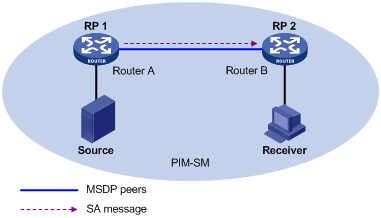
The work process of Anycast RP is as follows:
1. The multicast source registers with the nearest RP. In this example, Source registers with RP 1, with its multicast data encapsulated in the register message. When the register message arrives at RP 1, RP 1 de-encapsulates the message.
2. Receivers send join messages to the nearest RP to join in the RPT rooted as this RP. In this example, Receiver joins the RPT rooted at RP 2.
3. RPs share the registered multicast information by means of SA messages. In this example, RP 1 creates an SA message and sends it to RP 2, with the multicast data from Source encapsulated in the SA message. When the SA message reaches RP 2, RP 2 de-encapsulates the message.
4. Receivers receive the multicast data along the RPT and directly join the SPT rooted at the multicast source. In this example, RP 2 forwards the multicast data down the RPT. When Receiver receives the multicast data from Source, it directly joins the SPT rooted at Source.
The significance of Anycast RP is as follows:
· Optimal RP path—A multicast source registers with the nearest RP so that an SPT with the optimal path is built. A receiver joins the nearest RP so that an RPT with the optimal path is built.
· Load balancing between RPs—Each RP needs to maintain just part of the source/group information within the PIM-SM domain and forward part of the multicast data, thus achieving load balancing between different RPs.
· Redundancy backup between RPs—When an RP fails, the multicast source previously registered on it or the receivers that previously joined it will register with or join another nearest RP, achieving redundancy backup between RPs.
|
|
CAUTION: · Be sure to configure a 32-bit subnet mask (255.255.255.255) for the Anycast RP address. Namely, be sure to configure the Anycast RP address into a host address. · An MSDP peer address must be different from the Anycast RP address. |
MSDP support for VPNs
The interfaces on the multicast routers in a VPN can set up MSDP peering relationships between each other. By exchanging SA messages between MSDP peers, multicast transmission in a VPN between different PIM-SM domains can be implemented.
To support MSDP for VPNs, a multicast router that runs MSDP maintains an independent set of MSDP mechanism for each VPN that it supports, including SA cache, peering connection, timers, sending cache, and cache for exchanging PIM messages. The information in one VPN is isolated from another, and MSDP and PIM-SM messages can be exchanged only within the same VPN.
Protocols and standards
· RFC 3618, Multicast Source Discovery Protocol (MSDP)
· RFC 3446, Anycast Rendezvous Point (RP) mechanism using Protocol Independent Multicast (PIM) and Multicast Source Discovery Protocol (MSDP)
MSDP configuration task list
Complete these tasks to configure MSDP:
|
Task |
Remarks |
|
|
Required |
||
|
Required |
||
|
Optional |
||
|
Optional |
||
|
Optional |
||
|
Optional |
||
|
Optional |
||
|
Optional |
||
|
Optional |
||
|
Optional |
||
Configuring basic MSDP functions
|
|
NOTE: All the configuration tasks should be carried out on RPs in PIM-SM domains, and each of these RPs acts as an MSDP peer. |
Configuration prerequisites
Before you configure basic MSDP functions, complete the following tasks:
· Configure any unicast routing protocol so that all devices in the domain are interoperable at the network layer
· Configuring PIM-SM to enable intra-domain multicast forwarding
· Determine the IP addresses of MSDP peers
· Determine the address prefix list for an RP address filtering policy
Enabling MSDP
Enabling MSDP globally in the public network
To enable MSDP globally in the public network:
|
Step |
Command |
Remarks |
|
1. Enter system view. |
system-view |
N/A |
|
2. Enable IP multicast routing. |
multicast routing-enable |
Disabled by default |
|
3. Enable MSDP and enter public network MSDP view. |
msdp |
Disabled by default |
Enabling MSDP in a VPN instance
|
|
CAUTION: When the system operates in standard mode, a reserved VLAN must be configured if you want to configure MSDP for VPNs. For information about how to configure a reserved VLAN, see MPLS Configuration Guide and MPLS Command Reference. |
To enable MSDP globally in a VPN instance:
|
Step |
Command |
Remarks |
|
1. Enter system view. |
system-view |
N/A |
|
2. Create a VPN instance and enter VPN instance view. |
ip vpn-instance vpn-instance-name |
N/A |
|
3. Configure a route-distinguisher (RD) for the VPN instance. |
route-distinguisher route-distinguisher |
No RD is configured by default. |
|
4. Enable IP multicast routing. |
multicast routing-enable |
Disabled by default. |
|
5. Return to system view. |
quit |
N/A |
|
6. Enable MSDP and enter VPN instance MSDP view. |
msdp vpn-instance vpn-instance-name |
Disabled by default. |
|
|
NOTE: · For more information about the ip vpn-instance and route-distinguisher commands, see MPLS Command Reference. · For more information about the multicast routing-enable command, see IP Multicast Command Reference. |
Creating an MSDP peer connection
An MSDP peering relationship is identified by an address pair, namely, the address of the local MSDP peer and that of the remote MSDP peer. An MSDP peer connection must be created on both devices that are a pair of MSDP peers.
To create an MSDP peer connection:
|
Step |
Command |
Remarks |
|
1. Enter system view. |
system-view |
N/A |
|
2. Enter public network MSDP view or VPN instance MSDP view. |
msdp [ vpn-instance vpn-instance-name ] |
N/A |
|
3. Create an MSDP peer connection. |
peer peer-address connect-interface interface-type interface-number |
No MSDP peer connection is created by default. |
|
|
NOTE: If an interface of the switch is shared by an MSDP peer and a BGP or MBGP peer at the same time, H3C recommends you to configure the IP address of the MSDP peer the same as that of the BGP or MBGP peer. |
Configuring a static RPF peer
Configuring static RPF peers avoids RPF check of SA messages.
To configure a static RPF peer:
|
Step |
Command |
Remarks |
|
1. Enter system view. |
system-view |
N/A |
|
2. Enter public network MSDP view or VPN instance MSDP view. |
msdp [ vpn-instance vpn-instance-name ] |
N/A |
|
3. Configure a static RPF peer. |
static-rpf-peer peer-address [ rp-policy ip-prefix-name ] |
No static RPF peer is configured by default. |
|
|
NOTE: If only one MSDP peer is configured on a switch, this MSDP will be registered as a static RPF peer. |
Configuring an MSDP peer connection
Configuration prerequisites
Before you configure MSDP peer connection, complete the following tasks:
· Configure any unicast routing protocol so that all devices in the domain are interoperable at the network layer
· Configure basic MSDP functions
· Determine the description of MSDP peers
· Determine the name of an MSDP mesh group
· Determine the MSDP peer connection retry interval
· Determine the MD5 authentication key for the TCP connection to be established with an MSDP peer
Configuring MSDP peer description
With the MSDP peer description information, the administrator can easily distinguish different MSDP peers and thus better manage MSDP peers.
To configure description for an MSDP peer:
|
Step |
Command |
Remarks |
|
1. Enter system view. |
system-view |
N/A |
|
2. Enter public network MSDP view or VPN instance MSDP view. |
msdp [ vpn-instance vpn-instance-name ] |
N/A |
|
3. Configure description for an MSDP peer. |
peer peer-address description text |
No description is configured for MSDP peers by default. |
Configuring an MSDP mesh group
An AS can contain multiple MSDP peers. You can use the MSDP mesh group mechanism to avoid SA message flooding among these MSDP peers and optimize the multicast traffic.
An MSDP peer in an MSDP mesh group forwards SA messages from outside the mesh group that have passed the RPF check to the other members in the mesh group. A mesh group member accepts SA messages from inside the group without performing an RPF check, and does not forward the message within the mesh group. This mechanism not only avoids SA flooding but also simplifies the RPF check mechanism, because no need exists to run BGP or MBGP between these MSDP peers.
By configuring the same mesh group name for multiple MSDP peers, you can create a mesh group and assign those MSDP peers to that mesh group.
To create an MSDP mesh group:
|
Step |
Command |
Remarks |
|
1. Enter system view. |
system-view |
N/A |
|
2. Enter public network MSDP view or VPN instance MSDP view. |
msdp [ vpn-instance vpn-instance-name ] |
N/A |
|
3. Create an MSDP mesh group and assign an MSDP peer to that mesh group. |
peer peer-address mesh-group name |
An MSDP peer does not belong to any mesh group by default. |
|
|
NOTE: · Before grouping multiple switches into an MSDP mesh group, make sure that these devices are interconnected with one another. · If you configure more than one mesh group name on an MSDP peer, only the last configuration is effective. |
Configuring MSDP peer connection control
MSDP peers are interconnected over TCP (port number 639). You can flexibly control sessions between MSDP peers by manually deactivating and reactivating the MSDP peering connections. When the connection between two MSDP peers is deactivated, SA messages will no longer be delivered between them, and the TCP connection is closed without any connection setup retry. The configuration information remain unchanged.
A TCP connection is required in the following situations:
· When a new MSDP peer is created
· When a previously deactivated MSDP peer connection is reactivated
· When a previously failed MSDP peer attempts to resume operation
You can adjust the interval between MSDP peering connection retries.
To enhance MSDP security, you can configure an MD5 authentication key for the TCP connection to be established with an MSDP peer. If the MD5 authentication fails, the TCP connection cannot be established.
To configure MSDP peer connection control:
|
Step |
Command |
Remarks |
|
1. Enter system view. |
system-view |
N/A |
|
2. Enter public network MSDP view or VPN instance MSDP view. |
msdp [ vpn-instance vpn-instance-name ] |
N/A |
|
3. Deactivate an MSDP peer. |
shutdown peer-address |
Optional. Active by default. |
|
4. Configure the interval between MSDP peer connection retries. |
timer retry interval |
Optional. 30 seconds by default. |
|
5. Configure an MD5 authentication key for the TCP connection to be established with an MSDP peer. |
peer peer-address password { cipher | simple } password |
Optional. By default, MD5 authentication is not performed before an TCP connection is established. |
|
|
CAUTION: The MSDP peers involved in the MD5 authentication must have the same authentication method and key. Otherwise, the authentication fails and the TCP connection cannot be established. |
Configuring SA messages related parameters
Configuration prerequisites
Before you configure SA message delivery, complete the following tasks:
· Configure any unicast routing protocol so that all devices in the domain are interoperable at the network layer
· Configuring basic MSDP functions
· Determine the ACL rules for filtering SA request messages
· Determine the ACL rules as SA message creation rules
· Determine the ACL rules for filtering SA messages to be received and forwarded
· Determine the TTL threshold for multicast packet encapsulation in SA messages
· Determine the maximum number of (S, G) entries learned from the specified MSDP peer that the switch can cache
Configuring SA message content
Some multicast sources send multicast data at an interval longer than the aging time of (S, G) entries. In this case, the source-side DR must encapsulate multicast data packet by packet in register messages and send them to the source-side RP. The source-side RP transmits the (S, G) information to the remote RP through SA messages. Then the remote RP joins the source-side DR and builds an SPT. Because the (S, G) entries have timed out, remote receivers can never receive the multicast data from the multicast source.
After the source-side RP is enabled to encapsulate multicast data in SA messages, if the RP wants to sends a multicast packet, it encapsulates the multicast packet in an SA message and sends it. After receiving the SA message, the remote RP de-encapsulates the SA message and delivers the multicast packet to the receivers in the local domain along the RPT.
The MSDP peers deliver SA messages to one another. After receiving an SA message, a switch performs RPF check on the message. If the switch finds that the remote RP address is the same as the local RP address, it discards the SA message. In the Anycast RP application, however, you must configure RPs with the same IP address on two or more devices in the same PIM-SM domain, and configure these devices as MSDP peers to one another. Therefore, a logic RP address (namely the RP address on the logic interface) that is different from the actual RP address must be designated for SA messages so that the messages can pass the RPF check.
To configure the SA message content:
|
Step |
Command |
Remarks |
|
1. Enter system view. |
system-view |
N/A |
|
2. Enter public network MSDP view or VPN instance MSDP view. |
msdp [ vpn-instance vpn-instance-name ] |
N/A |
|
3. Enable encapsulation of multicast data in SA messages. |
encap-data-enable |
Optional Disabled by default |
|
4. Configure the interface address as the RP address in SA messages. |
originating-rp interface-type interface-number |
Optional PIM RP address by default |
Configuring SA request messages
To configure SA message transmission and filtering:
|
Step |
Command |
Remarks |
|
1. Enter system view. |
system-view |
N/A |
|
2. Enter public network MSDP view or VPN instance MSDP view. |
msdp [ vpn-instance vpn-instance-name ] |
N/A |
|
3. Enable the device to send SA request messages. |
peer peer-address request-sa-enable |
Optional. Disabled by default. |
|
4. Configure a filtering rule for SA request messages. |
peer peer-address sa-request-policy [ acl acl-number ] |
Optional. SA request messages are not filtered by default. |
|
|
CAUTION: Before you can enable the device to send SA requests, be sure to disable the SA message cache mechanism. |
Configuring SA message filtering rules
By configuring an SA message creation rule, you can enable the switch to filter the (S, G) entries to be advertised when creating an SA message, so that the propagation of messages of multicast sources is controlled.
By configuring a filtering rule for receiving or forwarding SA messages, you can enable the switch to filter the (S, G) forwarding entries to be advertised when receiving or forwarding an SA message, so that the propagation of multicast source information is controlled at SA message reception or forwarding.
By configuring a TTL threshold for multicast data packet encapsulation in SA messages, you can control the multicast data packet encapsulation in SA messages and limit the propagation range of SA messages:
· Before creating an SA message with an encapsulated multicast data packet, the switch checks the TTL value of the multicast data packet. If the TTL value is less than the threshold, the switch does not create an SA message. If the TTL value is greater than or equal to the threshold, the switch encapsulates the multicast data in an SA message and sends the SA message.
· After receiving an SA message with an encapsulated multicast data packet, the switch decrements the TTL value of the multicast packet by 1 and then checks the TTL value. If the TTL value is less than the threshold, the switch does not forward the SA message to the designated MSDP peer. If the TTL value is greater than or equal to the threshold, the switch re-encapsulates the multicast data in an SA message and sends the SA message.
To configure a filtering rule for receiving or forwarding SA messages:
|
Step |
Command |
Remarks |
|
1. Enter system view. |
system-view |
N/A |
|
2. Enter public network MSDP view or VPN instance MSDP view. |
msdp [ vpn-instance vpn-instance-name ] |
N/A |
|
3. Configure an SA message creation rule. |
import-source [ acl acl-number ] |
No restrictions on (S, G) entries by default |
|
4. Configure a filtering rule for receiving or forwarding SA messages. |
peer peer-address sa-policy { import | export } [ acl acl-number ] |
No filtering rule by default |
|
5. Configure the TTL threshold for multicast data packet encapsulation in SA messages. |
peer peer-address minimum-ttl ttl-value |
Optional 0 by default |
Configuring the SA cache mechanism
To reduce the time spent in obtaining the multicast information, you can enable the SA cache mechanism to cache (S, G) entries contained in SA messages locally on the switch. However, caching (S, G) entries uses memory space on the switch.
When the SA cache mechanism is enabled and the switch receives a new (*, G) join message, the switch searches its SA cache first.
· If the corresponding (S, G) entry does not exist in the cache, the switch waits for the SA message that its MSDP peer will send in the next cycle.
· If the corresponding (S, G) entry exists in the cache, the switch joins the corresponding SPT rooted at S.
To protect the switch against denial of service (DoS) attacks, you can set a limit on the number of (S, G) entries the switch can cache.
To configure the SA message cache:
|
Step |
Command |
Remarks |
|
1. Enter system view. |
system-view |
N/A |
|
2. Enter public network MSDP view or VPN instance MSDP view. |
msdp [ vpn-instance vpn-instance-name ] |
N/A |
|
3. Enable the SA cache mechanism. |
cache-sa-enable |
Optional Enabled by default |
|
4. Configure the maximum number of (S, G) entries learned from the specified MSDP peer that the switch can cache. |
peer peer-address sa-cache-maximum sa-limit |
Optional 8192 by default |
Displaying and maintaining MSDP
|
Task |
Command |
Remarks |
|
1. Display the brief information of MSDP peers. |
display msdp [ all-instance | vpn-instance vpn-instance-name ] brief [ state { connect | down | listen | shutdown | up } ] [ | { begin | exclude | include } regular-expression ] |
Available in any view |
|
2. Display detailed information about the status of MSDP peers. |
display msdp [ all-instance | vpn-instance vpn-instance-name ] peer-status [ peer-address ] [ | { begin | exclude | include } regular-expression ] |
Available in any view |
|
3. Display the (S, G) entry information in the SA cache. |
display msdp [ all-instance | vpn-instance vpn-instance-name ] sa-cache [ group-address | source-address | as-number ] * [ | { begin | exclude | include } regular-expression ] |
Available in any view |
|
4. Display the number of (S, G) entries in the SA cache. |
display msdp [ all-instance | vpn-instance vpn-instance-name ] sa-count [ as-number ] [ | { begin | exclude | include } regular-expression ] |
Available in any view |
|
5. Reset the TCP connection with an MSDP peer. |
reset msdp [ all-instance | vpn-instance vpn-instance-name ] peer [ peer-address ] |
Available in user view |
|
6. Clear (S, G) entries in the SA cache. |
reset msdp [ all-instance | vpn-instance vpn-instance-name ] sa-cache [ group-address ] |
Available in user view |
|
7. Clear the statistics for an MSDP peer. |
reset msdp [ all-instance | vpn-instance vpn-instance-name ] statistics [ peer-address ] |
Available in user view |
MSDP configuration examples
|
|
NOTE: By default, Ethernet interfaces, VLAN interfaces, and aggregate interfaces are in the state of DOWN. To configure such an interface, use the undo shutdown command to bring it up first. |
PIM-SM Inter-domain multicast configuration
Network requirements
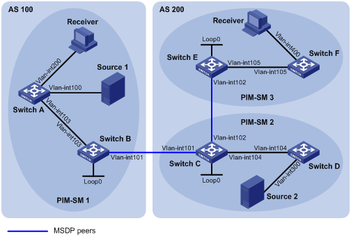
As shown in Figure 5, AS 100 and AS 200 are two ASs. BGP runs between the two ASs. PIM-SM 1 belongs to AS 100, and PIM-SM 2 and PIM-SM 3 belong to AS 200. Each PIM-SM domain has at least one multicast source or receiver.
Configure Loopback 0 as the C-BSR and C-RP of the related PIM-SM domain on Switch B, Switch C, and Switch E.
Set up MSDP peering relationships between the RPs of the PIM-SM domains to share multicast source information among the PIM-SM domains.
|
Interface |
IP address |
Device |
Interface |
IP address |
|
|
Switch A |
Vlan-int103 |
10.110.1.2/24 |
Switch D |
Vlan-int104 |
10.110.4.2/24 |
|
|
Vlan-int100 |
10.110.2.1/24 |
|
Vlan-int300 |
10.110.5.1/24 |
|
|
Vlan-int200 |
10.110.3.1/24 |
Switch E |
Vlan-int105 |
10.110.6.1/24 |
|
Switch B |
Vlan-int103 |
10.110.1.1/24 |
|
Vlan-int102 |
192.168.3.2/24 |
|
|
Vlan-int101 |
192.168.1.1/24 |
|
Loop0 |
3.3.3.3/32 |
|
|
Loop0 |
1.1.1.1/32 |
Switch F |
Vlan-int105 |
10.110.6.2/24 |
|
Switch C |
Vlan-int104 |
10.110.4.1/24 |
|
Vlan-int400 |
10.110.7.1/24 |
|
|
Vlan-int102 |
192.168.3.1/24 |
Source 1 |
— |
10.110.2.100/24 |
|
|
Vlan-int101 |
192.168.1.2/24 |
Source 2 |
— |
10.110.5.100/24 |
|
|
Loop0 |
2.2.2.2/32 |
|
|
|
Configuration procedure
1. Configure IP addresses and unicast routing:
Configure the IP address and subnet mask for each interface as per Figure 5. (Details not shown)
Configure OSPF for interconnection between switches in each AS. Ensure the network-layer interoperation among each AS, and ensure the dynamic update of routing information between the switches through a unicast routing protocol. (Details not shown)
2. Enable IP multicast routing, enable PIM-SM on each interface, and configure a PIM-SM domain border:
# Enable IP multicast routing on Switch A, enable PIM-SM on each interface, and enable IGMP on the host-side interface VLAN-interface 200.
<SwitchA> system-view
[SwitchA] multicast routing-enable
[SwitchA] interface vlan-interface 103
[SwitchA-Vlan-interface103] pim sm
[SwitchA-Vlan-interface103] quit
[SwitchA] interface vlan-interface 100
[SwitchA-Vlan-interface100] pim sm
[SwitchA-Vlan-interface100] quit
[SwitchA] interface vlan-interface 200
[SwitchA-Vlan-interface200] igmp enable
[SwitchA-Vlan-interface200] pim sm
[SwitchA-Vlan-interface200] quit
The configuration on Switch B, Switch C, Switch D, Switch E, and Switch F is similar to the configuration on Switch A.
# Configure a PIM domain border on Switch B.
[SwitchB] interface vlan-interface 101
[SwitchB-Vlan-interface101] pim bsr-boundary
[SwitchB-Vlan-interface101] quit
The configuration on Switch C and Switch E is similar to the configuration on Switch B.
3. Configure C-BSRs and C-RPs:
# Configure Loopback 0 as a C-BSR and a C-RP on Switch B.
[SwitchB] pim
[SwitchB-pim] c-bsr loopback 0
[SwitchB-pim] c-rp loopback 0
[SwitchB-pim] quit
The configuration on Switch C and Switch E is similar to the configuration on Switch B.
4. Configure BGP for mutual route redistribution between BGP and OSPF:
# Configure an EBGP peer, and redistribute OSPF routes on Switch B.
[SwitchB] bgp 100
[SwitchB-bgp] router-id 1.1.1.1
[SwitchB-bgp] peer 192.168.1.2 as-number 200
[SwitchB-bgp] import-route ospf 1
[SwitchB-bgp] quit
# Configure an EBGP peer, and redistribute OSPF routes on Switch C.
[SwitchC] bgp 200
[SwitchC-bgp] router-id 2.2.2.2
[SwitchC-bgp] peer 192.168.1.1 as-number 100
[SwitchC-bgp] import-route ospf 1
[SwitchC-bgp] quit
# Redistribute BGP routes into OSPF on Switch B.
[SwitchB] ospf 1
[SwitchB-ospf-1] import-route bgp
[SwitchB-ospf-1] quit
# Redistribute BGP routes into OSPF on Switch C.
[SwitchB] ospf 1
[SwitchB-ospf-1] import-route bgp
[SwitchB-ospf-1] quit
5. Configure MSDP peers:
# Configure an MSDP peer on Switch B.
[SwitchB] msdp
[SwitchB-msdp] peer 192.168.1.2 connect-interface vlan-interface 101
[SwitchB-msdp] quit
# Configure an MSDP peer on Switch C.
[SwitchC] msdp
[SwitchC-msdp] peer 192.168.1.1 connect-interface vlan-interface 101
[SwitchC-msdp] peer 192.168.3.2 connect-interface vlan-interface 102
[SwitchC-msdp] quit
# Configure MSDP peers on Switch E.
[SwitchE] msdp
[SwitchE-msdp] peer 192.168.3.1 connect-interface vlan-interface 102
[SwitchE-msdp] quit
6. Verify the configuration:
# Display information about BGP peering relationships on Switch B.
[SwitchB] display bgp peer
BGP local router ID : 1.1.1.1
Local AS number : 100
Total number of peers : 1 Peers in established state : 1
Peer AS MsgRcvd MsgSent OutQ PrefRcv Up/Down State
192.168.1.2 200 24 21 0 6 00:13:09 Established
# Display information about BGP peering relationships on Switch C.
[SwitchC] display bgp peer
BGP local router ID : 2.2.2.2
Local AS number : 200
Total number of peers : 1 Peers in established state : 1
Peer AS MsgRcvd MsgSent OutQ PrefRcv Up/Down State
192.168.1.1 100 18 16 0 1 00:12:04 Established
# Display BGP routing table information on Switch C.
[SwitchC] display bgp routing-table
Total Number of Routes: 5
BGP Local router ID is 2.2.2.2
Status codes: * - valid, ^ - VPNv4 best, > - best, d - damped,
h - history, i - internal, s - suppressed, S - Stale
Origin : i - IGP, e - EGP, ? - incomplete
Network NextHop MED LocPrf PrefVal Path/Ogn
* > 1.1.1.1/32 192.168.1.1 0 0 100?
* >i 2.2.2.2/32 0.0.0.0 0 0 ?
* > 192.168.1.0 0.0.0.0 0 0 ?
* > 192.168.1.1/32 0.0.0.0 0 0 ?
* > 192.168.1.2/32 0.0.0.0 0 0 ?
When the multicast source in PIM-SM 1 (Source 1) and the multicast source in PIM-SM 2 (Source 2) send multicast information, receivers in PIM-SM 1 and PIM-SM 3 can receive the multicast data. You can use the display msdp brief command to view the brief information of MSDP peering relationships between the switches. For example:
# Display brief information about MSDP peering relationships on Switch B.
[SwitchB] display msdp brief
MSDP Peer Brief Information of VPN-Instance: public net
Configured Up Listen Connect Shutdown Down
1 1 0 0 0 0
Peer's Address State Up/Down time AS SA Count Reset Count
192.168.1.2 Up 00:12:27 200 13 0
# Display brief information about MSDP peering relationships on Switch C.
[SwitchC] display msdp brief
MSDP Peer Brief Information of VPN-Instance: public net
Configured Up Listen Connect Shutdown Down
2 2 0 0 0 0
Peer's Address State Up/Down time AS SA Count Reset Count
192.168.3.2 Up 00:15:32 200 8 0
192.168.1.1 Up 00:06:39 100 13 0
# Display brief information about MSDP peering relationships on Switch E.
[SwitchE] display msdp brief
MSDP Peer Brief Information of VPN-Instance: public net
Configured Up Listen Connect Shutdown Down
1 1 0 0 0 0
Peer's Address State Up/Down time AS SA Count Reset Count
192.168.3.1 Up 01:07:08 200 8 0
# Display detailed MSDP peer information on Switch B.
[SwitchB] display msdp peer-status
MSDP Peer Information of VPN-Instance: public net
MSDP Peer 192.168.1.2, AS 200
Description:
Information about connection status:
State: Up
Up/down time: 00:15:47
Resets: 0
Connection interface: Vlan-interface101 (192.168.1.1)
Number of sent/received messages: 16/16
Number of discarded output messages: 0
Elapsed time since last connection or counters clear: 00:17:51
Information about (Source, Group)-based SA filtering policy:
Import policy: none
Export policy: none
Information about SA-Requests:
Policy to accept SA-Request messages: none
Sending SA-Requests status: disable
Minimum TTL to forward SA with encapsulated data: 0
SAs learned from this peer: 0, SA-cache maximum for the peer: none
Input queue size: 0, Output queue size: 0
Counters for MSDP message:
Count of RPF check failure: 0
Incoming/outgoing SA messages: 0/0
Incoming/outgoing SA requests: 0/0
Incoming/outgoing SA responses: 0/0
Incoming/outgoing data packets: 0/0
Inter-AS multicast configuration by leveraging static RPF peers
Network requirements
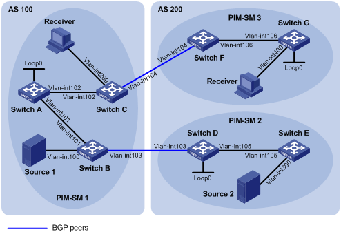
· As shown in Figure 6, AS 100 and AS 200 are two ASs running OSPF. BGP runs between the two ASs.
· PIM-SM 1 belongs to AS 100, and PIM-SM 2 and PIM-SM 3 belong to AS 200. Each PIM-SM domain has at least one multicast source or receiver.
· Configure Loopback 0 as a C-BSR and C-RP of the related PIM-SM domain on Switch A, Switch D and Switch G.
· According to the RPF principle, the device can receive SA messages that pass the filtering policy from its static RPF peers. To share multicast source information among PIM-SM domains without changing the unicast topology structure, configure MSDP peering relationships for the RPs of the PIM-SM domains and configure static RPF peering relationships for the MSDP peers to share multicast source information among the PIM-SM domains.
|
Device |
Interface |
IP address |
Device |
Interface |
IP address |
|
Source 1 |
- |
192.168.1.100/24 |
Switch D |
Vlan-int105 |
10.110.5.1/24 |
|
Source 2 |
- |
192.168.3.100/24 |
|
Vlan-int103 |
10.110.3.2/24 |
|
Switch A |
Vlan-int101 |
10.110.1.1/24 |
|
Loop0 |
2.2.2.2/32 |
|
|
Vlan-int102 |
10.110.2.1/24 |
Switch E |
Vlan-int105 |
10.110.5.2/24 |
|
|
Loop0 |
1.1.1.1/32 |
|
Vlan-int300 |
192.168.3.1/24 |
|
Switch B |
Vlan-int101 |
10.110.1.2/24 |
Switch F |
Vlan-int106 |
10.110.6.1/24 |
|
|
Vlan-int100 |
192.168.1.1/24 |
|
Vlan-int104 |
10.110.4.2/24 |
|
|
Vlan-int103 |
10.110.3.1/24 |
Switch G |
Vlan-int106 |
10.110.6.2/24 |
|
Switch C |
Vlan-int102 |
10.110.2.2/24 |
|
Vlan-int400 |
192.168.4.1/24 |
|
|
Vlan-int200 |
192.168.2.1/24 |
|
Loop0 |
3.3.3.3/32 |
|
|
Vlan-int104 |
10.110.4.1/24 |
|
|
|
Configuration procedure
1. Configure IP addresses and unicast routing:
Configure the IP address and subnet mask for each interface as per Figure 6. (Details not shown)
Configure OSPF for interconnection between the switches. Ensure the network-layer interoperation in each AS, and ensure the dynamic update of routing information among the switches through a unicast routing protocol. (Details not shown)
2. Enable IP multicast routing, enable PIM-SM and IGMP, and configure a PIM-SM domain border:
# Enable IP multicast routing on Switch C, enable PIM-SM on each interface, and enable IGMP on the host-side interface VLAN-interface 200.
<SwitchC> system-view
[SwitchC] multicast routing-enable
[SwitchC] interface vlan-interface 102
[SwitchC-Vlan-interface102] pim sm
[SwitchC-Vlan-interface102] quit
[SwitchC] interface vlan-interface 200
[SwitchC-Vlan-interface200] igmp enable
[SwitchC-Vlan-interface200] pim sm
[SwitchC-Vlan-interface200] quit
[SwitchC] interface vlan-interface 104
[SwitchC-Vlan-interface104] pim sm
[SwitchC-Vlan-interface104] quit
The configuration on Switch A, Switch B, Switch D, Switch E, Switch F, and Switch G is similar to that on Switch A. (Details not shown)
# Configure PIM domain borders on Switch B.
[SwitchB] interface vlan-interface 103
[SwitchB-Vlan-interface103] pim bsr-boundary
[SwitchB-Vlan-interface103] quit
The configuration on Switch C, Switch D, and Switch F is similar to that on Switch B. (Details not shown)
3. Configure C-BSRs and C-RPs:
# Configure Loopback 0 as a C-BSR and a C-RP on Switch A.
[SwitchA] pim
[SwitchA-pim] c-bsr loopback 0
[SwitchA-pim] c-rp loopback 0
[SwitchA-pim] quit
The configuration on Switch D and Switch G is similar to that on Switch A. (Details not shown)
4. Configure BGP, and redistribute BGP routing information into OSPF, and OSPF routing information into BGP:
# Configure the EBGP peer, and redistribute OSPF routing information on Switch B.
[SwitchB] bgp 100
[SwitchB-bgp] router-id 1.1.1.2
[SwitchB-bgp] peer 10.110.3.2 as-number 200
[SwitchB-bgp] import-route ospf 1
[SwitchB-bgp] quit
# Configure the EBGP peer, and redistribute OSPF routing information on Switch D.
[SwitchD] bgp 200
[SwitchD-bgp] router-id 2.2.2.2
[SwitchD-bgp] peer 10.110.3.1 as-number 100
[SwitchD-bgp] import-route ospf 1
[SwitchD-bgp] quit
# Configure the EBGP peer, and redistribute OSPF routing information on Switch C.
[SwitchC] bgp 100
[SwitchC-bgp] router-id 1.1.1.3
[SwitchC-bgp] peer 10.110.4.2 as-number 200
[SwitchC-bgp] import-route ospf 1
[SwitchC-bgp] quit
# Configure the EBGP peer, and redistribute OSPF routing information on Switch F.
[SwitchF] bgp 200
[SwitchF-bgp] router-id 3.3.3.1
[SwitchF-bgp] peer 10.110.4.1 as-number 100
[SwitchF-bgp] import-route ospf 1
[SwitchF-bgp] quit
# Redistribute BGP routing information into OSPF on Switch B.
[SwitchB] ospf 1
[SwitchB-ospf-1] import-route bgp
[SwitchB-ospf-1] quit
# Redistribute BGP routing information into OSPF on Switch D.
[SwitchD] ospf 1
[SwitchD-ospf-1] import-route bgp
[SwitchD-ospf-1] quit
# Redistribute BGP routing information into OSPF on Switch C.
[SwitchC] ospf 1
[SwitchC-ospf-1] import-route bgp
[SwitchC-ospf-1] quit
# Redistribute BGP routing information into OSPF on Switch F.
[SwitchF] ospf 1
[SwitchF-ospf-1] import-route bgp
[SwitchF-ospf-1] quit
5. Configure MSDP peers and static RPF peers:
# Configure Switch D and Switch G as the MSDP peers and static RPF peers of Switch A.
[SwitchA] ip ip-prefix list-dg permit 10.110.0.0 16 greater-equal 16 less-equal 32
[SwitchA] msdp
[SwitchA-msdp] peer 10.110.3.2 connect-interface vlan-interface 101
[SwitchA-msdp] peer 10.110.6.2 connect-interface vlan-interface 102
[SwitchA-msdp] static-rpf-peer 10.110.3.2 rp-policy list-dg
[SwitchA-msdp] static-rpf-peer 10.110.6.2 rp-policy list-dg
[SwitchA-msdp] quit
# Configure Switch A as the MSDP peer and static RPF peer of Switch D.
[SwitchD] ip ip-prefix list-a permit 10.110.0.0 16 greater-equal 16 less-equal 32
[SwitchD] msdp
[SwitchD-msdp] peer 10.110.1.1 connect-interface vlan-interface 103
[SwitchD-msdp] static-rpf-peer 10.110.1.1 rp-policy list-a
[SwitchD-msdp] quit
# Configure Switch A as the MSDP peer and static RPF peer of Switch G.
[SwitchG] ip ip-prefix list-a permit 10.110.0.0 16 greater-equal 16 less-equal 32
[SwitchG] msdp
[SwitchG-msdp] peer 10.110.2.1 connect-interface vlan-interface 106
[SwitchG-msdp] static-rpf-peer 10.110.2.1 rp-policy list-a
[SwitchG-msdp] quit
6. Verify the configuration:
Use the display bgp peer command to view the BGP peering relationships between the switches. If the command gives no output on Switch A, it means that no BGP peering relationship has been established between Switch A and Switch D, or between Switch A and Switch G.
When the multicast source in PIM-SM 1 (Source 1) and the multicast source in PIM-SM 2 (Source 2) send multicast information, receivers in PIM-SM 1 and PIM-SM 3 can receive the multicast data. You can use the display msdp brief command to view the brief information of MSDP peering relationships between the switches. For example:
# Display brief MSDP peer information on Switch A.
[SwitchA] display msdp brief
MSDP Peer Brief Information of VPN-Instance: public net
Configured Up Listen Connect Shutdown Down
2 2 0 0 0 0
Peer's Address State Up/Down time AS SA Count Reset Count
10.110.3.2 Up 01:07:08 ? 8 0
10.110.6.2 Up 00:16:39 ? 13 0
# Display brief MSDP peer information on Switch D.
[SwitchD] display msdp brief
MSDP Peer Brief Information of VPN-Instance: public net
Configured Up Listen Connect Shutdown Down
1 1 0 0 0 0
Peer's Address State Up/Down time AS SA Count Reset Count
10.110.1.1 Up 01:07:09 ? 8 0
# Display brief MSDP peer information on Switch G.
[SwitchG] display msdp brief
MSDP Peer Brief Information of VPN-Instance: public net
Configured Up Listen Connect Shutdown Down
1 1 0 0 0 0
Peer's Address State Up/Down time AS SA Count Reset Count
10.110.2.1 Up 00:16:40 ? 13 0
Anycast RP configuration
Network requirements
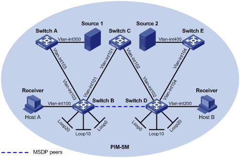
· As shown in Figure 7, the PIM-SM domain has multiple multicast sources and receivers. OSPF runs within the domain to provide unicast routes.
· Configure the Anycast RP application so that the receiver-side DRs and the source-side DRs can initiate a Join message to their respective RPs that are the topologically nearest to them.
· On Switch B and Switch D, configure the interface Loopback 10 as a C-BSR, and Loopback 20 as a C-RP.
· The router ID of Switch B is 1.1.1.1, and the router ID of Switch D is 2.2.2.2. Set up an MSDP peering relationship between Switch B and Switch D.
|
Device |
Interface |
IP address |
Device |
Interface |
IP address |
|
Source 1 |
— |
10.110.5.100/24 |
Switch C |
Vlan-int101 |
192.168.1.2/24 |
|
Source 2 |
— |
10.110.6.100/24 |
|
Vlan-int102 |
192.168.2.2/24 |
|
Switch A |
Vlan-int300 |
10.110.5.1/24 |
Switch D |
Vlan-int200 |
10.110.3.1/24 |
|
|
Vlan-int103 |
10.110.2.2/24 |
|
Vlan-int104 |
10.110.4.1/24 |
|
Switch B |
Vlan-int100 |
10.110.1.1/24 |
|
Vlan-int102 |
192.168.2.1/24 |
|
|
Vlan-int103 |
10.110.2.1/24 |
|
Loop0 |
2.2.2.2/32 |
|
|
Vlan-int101 |
192.168.1.1/24 |
|
Loop10 |
4.4.4.4/32 |
|
|
Loop0 |
1.1.1.1/32 |
|
Loop20 |
10.1.1.1/32 |
|
|
Loop10 |
3.3.3.3/32 |
Switch E |
Vlan-int400 |
10.110.6.1/24 |
|
|
Loop20 |
10.1.1.1/32 |
|
Vlan-int104 |
10.110.4.2/24 |
Configuration procedure
1. Configure IP addresses and unicast routing:
Configure the IP address and subnet mask for each interface as per Figure 7. (Details not shown)
Configure OSPF for interconnection between the switches. Ensure the network-layer interoperation among the switches, and ensure the dynamic update of routing information between the switches through a unicast routing protocol. (Details not shown)
2. Enable IP multicast routing, and enable PIM-SM and IGMP:
# Enable IP multicast routing on Switch B, enable PIM-SM on each interface, and enable IGMP on the host-side interface VLAN-interface 100.
<SwitchB> system-view
[SwitchB] multicast routing-enable
[SwitchB] interface vlan-interface 100
[SwitchB-Vlan-interface100] igmp enable
[SwitchB-Vlan-interface100] pim sm
[SwitchB-Vlan-interface100] quit
[SwitchB] interface vlan-interface 103
[SwitchB-Vlan-interface103] pim sm
[SwitchB-Vlan-interface103] quit
[SwitchB] interface Vlan-interface 101
[SwitchB-Vlan-interface101] pim sm
[SwitchB-Vlan-interface101] quit
[SwitchB] interface loopback 0
[SwitchB-LoopBack0] pim sm
[SwitchB-LoopBack0] quit
[SwitchB] interface loopback 10
[SwitchB-LoopBack10] pim sm
[SwitchB-LoopBack10] quit
[SwitchB] interface loopback 20
[SwitchB-LoopBack20] pim sm
[SwitchB-LoopBack20] quit
The configuration on Switch A, Switch C, Switch D, and Switch E is similar to the configuration on Switch B.
3. Configure C-BSRs and C-RPs:
# Configure Loopback 10 as a C-BSR and Loopback 20 as a C-RP on Switch B.
[SwitchB] pim
[SwitchB-pim] c-bsr loopback 10
[SwitchB-pim] c-rp loopback 20
[SwitchB-pim] quit
The configuration on Switch D is similar to the configuration on Switch B.
4. Configure MSDP peers:
# Configure an MSDP peer on Loopback 0 of Switch B.
[SwitchB] msdp
[SwitchB-msdp] originating-rp loopback 0
[SwitchB-msdp] peer 2.2.2.2 connect-interface loopback 0
[SwitchB-msdp] quit
# Configure an MSDP peer on Loopback 0 of Switch D.
[SwitchD] msdp
[SwitchD-msdp] originating-rp loopback 0
[SwitchD-msdp] peer 1.1.1.1 connect-interface loopback 0
[SwitchD-msdp] quit
5. Verify the configuration:
You can use the display msdp brief command to view the brief information of MSDP peering relationships between the switches.
# Display brief MSDP peer information on Switch B.
[SwitchB] display msdp brief
MSDP Peer Brief Information of VPN-Instance: public net
Configured Up Listen Connect Shutdown Down
1 1 0 0 0 0
Peer's Address State Up/Down time AS SA Count Reset Count
2.2.2.2 Up 00:10:17 ? 0 0
# Display brief MSDP peer information on Switch D.
[SwitchD] display msdp brief
MSDP Peer Brief Information of VPN-Instance: public net
Configured Up Listen Connect Shutdown Down
1 1 0 0 0 0
Peer's Address State Up/Down time AS SA Count Reset Count
1.1.1.1 Up 00:10:18 ? 0 0
To view the PIM routing information on the switches, use the display pim routing-table command. When Source 1 (10.110.5.100/24) sends multicast data to multicast group G (225.1.1.1), Host A joins multicast group G. By comparing the PIM routing information displayed on Switch B with that displayed on Switch D, you can see that Switch B acts now as the RP for Source 1 and Host A.
# Display PIM routing information on Switch B.
[SwitchB] display pim routing-table
VPN-Instance: public net
Total 1 (*, G) entry; 1 (S, G) entry
(*, 225.1.1.1)
RP: 10.1.1.1 (local)
Protocol: pim-sm, Flag: WC
UpTime: 00:15:04
Upstream interface: Register
Upstream neighbor: NULL
RPF prime neighbor: NULL
Downstream interface(s) information:
Total number of downstreams: 1
1: Vlan-interface100
Protocol: igmp, UpTime: 00:15:04, Expires: -
(10.110.5.100, 225.1.1.1)
RP: 10.1.1.1 (local)
Protocol: pim-sm, Flag: SPT 2MSDP ACT
UpTime: 00:46:28
Upstream interface: Vlan-interface103
Upstream neighbor: 10.110.2.2
RPF prime neighbor: 10.110.2.2
Downstream interface(s) information:
Total number of downstreams: 1
1: Vlan-interface100
Protocol: pim-sm, UpTime: - , Expires: -
# Display PIM routing information on Switch D.
[SwitchD] display pim routing-table
No information is output on Switch D.
Host A has left multicast group G. Source 1 has stopped sending multicast data to multicast group G. When Source 2 (10.110.6.100/24) sends multicast data to G, Host B joins G. By comparing the PIM routing information displayed on Switch B with that displayed on Switch D, you can see that Switch D acts now as the RP for Source 2 and Host B.
# Display PIM routing information on Switch B.
[SwitchB] display pim routing-table
No information is output on Switch B.
# Display PIM routing information on Switch D.
[SwitchD] display pim routing-table
VPN-Instance: public net
Total 1 (*, G) entry; 1 (S, G) entry
(*, 225.1.1.1)
RP: 10.1.1.1 (local)
Protocol: pim-sm, Flag: WC
UpTime: 00:12:07
Upstream interface: Register
Upstream neighbor: NULL
RPF prime neighbor: NULL
Downstream interface(s) information:
Total number of downstreams: 1
1: Vlan-interface200
Protocol: igmp, UpTime: 00:12:07, Expires: -
(10.110.6.100, 225.1.1.1)
RP: 10.1.1.1 (local)
Protocol: pim-sm, Flag: SPT 2MSDP ACT
UpTime: 00:40:22
Upstream interface: Vlan-interface104
Upstream neighbor: 10.110.4.2
RPF prime neighbor: 10.110.4.2
Downstream interface(s) information:
Total number of downstreams: 1
1: Vlan-interface200
Protocol: pim-sm, UpTime: - , Expires: -
SA message filtering configuration
Network requirements
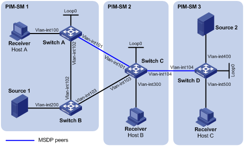
· As shown in Figure 8, three PIM-SM domains exist in the network, and OSPF runs within and among the domains to provide unicast routing.
· Configure respective Loopback 0 of Switch A, Switch C and Switch D as a C-BSR and C-RP in the respective PIM-SM domain.
· Set up an MSDP peering relationship between Switch A and Switch C and between Switch C and Switch D.
· Source 1 sends multicast data to multicast groups 225.1.1.0/30 and 226.1.1.0/30, and Source 2 sends multicast data to multicast group 227.1.1.0/30.
· Configure SA message filtering rules so that receivers Host A and Host B can receive only the multicast data addressed to multicast groups 225.1.1.0/30 and 226.1.1.0/30, and Host can receive only the multicast data addressed to multicast groups 226.1.1.0/30 and 227.1.1.0/30.
|
Device |
Interface |
IP address |
Device |
Interface |
IP address |
|
Source 1 |
— |
10.110.3.100/24 |
Switch C |
Vlan-int300 |
10.110.4.1/24 |
|
Source 2 |
— |
10.110.6.100/24 |
|
Vlan-int104 |
10.110.5.1/24 |
|
Switch A |
Vlan-int100 |
10.110.1.1/24 |
|
Vlan-int101 |
192.168.1.2/24 |
|
|
Vlan-int102 |
10.110.2.1/24 |
|
Vlan-int103 |
192.168.2.2/24 |
|
|
Vlan-int101 |
192.168.1.1/24 |
|
Loop0 |
2.2.2.2/32 |
|
|
Loop0 |
1.1.1.1/32 |
Switch D |
Vlan-int400 |
10.110.6.1/24 |
|
Switch B |
Vlan-int200 |
10.110.3.1/24 |
|
Vlan-int500 |
10.110.7.1/24 |
|
|
Vlan-int102 |
10.110.2.2/24 |
|
Vlan-int104 |
10.110.5.2/24 |
|
|
Vlan-int103 |
192.168.2.1/24 |
|
Loop0 |
3.3.3.3/32 |
Configuration Procedure
1. Configure IP addresses and unicast routing:
Configure the IP address and subnet mask for each interface as per Figure 8. (Details not shown)
Configure OSPF for interoperation among the switches. Ensure the network-layer interoperation within and between the PIM-SM domains and ensure dynamic update of routing information among the switches by leveraging unicast routing. (Details not shown)
2. Enable IP multicast routing, PIM-SM and IGMP, and configure a PIM domain border:
# On Switch A, enable IP multicast routing, enable PIM-SM on each interface, and enable IGMP on the host-side interface, VLAN-interface 100.
<SwitchA> system-view
[SwitchA] multicast routing-enable
[SwitchA] interface vlan-interface 100
[SwitchA-Vlan-interface100] igmp enable
[SwitchA-Vlan-interface100] pim sm
[SwitchA-Vlan-interface100] quit
[SwitchA] interface vlan-interface 101
[SwitchA-Vlan-interface101] pim sm
[SwitchA-Vlan-interface101] quit
[SwitchA] interface vlan-interface 102
[SwitchA-Vlan-interface102] pim sm
[SwitchA-Vlan-interface102] quit
[SwitchA] interface loopback 0
[SwitchA-LoopBack0] pim sm
[SwitchA-LoopBack0] quit
The configuration on Switch B, Switch C and Switch D is similar to the configuration on Switch A. (Details not shown)
# Configure a PIM domain border on Switch C.
[SwitchC] interface vlan-interface 101
[SwitchC-Vlan-interface101] pim bsr-boundary
[SwitchC-Vlan-interface101] quit
[SwitchC] interface vlan-interface 103
[SwitchC-Vlan-interface103] pim bsr-boundary
[SwitchC-Vlan-interface103] quit
[SwitchC] interface vlan-interface 104
[SwitchC-Vlan-interface104] pim bsr-boundary
[SwitchC-Vlan-interface104] quit
The configuration on Switch A, Switch B and Switch D is similar to the configuration on Switch C. (Details not shown)
3. Configure C-BSRs and C-RPs:
# Configure Loopback 0 as a C-BSR and a C-RP on Switch A.
[SwitchA] pim
[SwitchA-pim] c-bsr loopback 0
[SwitchA-pim] c-rp loopback 0
[SwitchA-pim] quit
The configuration on Switch C and Switch D is similar to the configuration on Switch A. (Details not shown)
4. Configure MSDP peers:
# Configure an MSDP peer on Switch A.
[SwitchA] msdp
[SwitchA-msdp] peer 192.168.1.2 connect-interface vlan-interface 101
[SwitchA-msdp] quit
# Configure MSDP peers on Switch C.
[SwitchC] msdp
[SwitchC-msdp] peer 192.168.1.1 connect-interface vlan-interface 101
[SwitchC-msdp] peer 10.110.5.2 connect-interface vlan-interface 104
[SwitchC-msdp] quit
# Configure an MSDP peer on Switch D.
[SwitchD] msdp
[SwitchD-msdp] peer 10.110.5.1 connect-interface vlan-interface 104
[SwitchD-msdp] quit
5. Configure SA message filtering rules:
# Configure an SA message rule on Switch C so that Switch C will not forward SA messages for (Source 1, 225.1.1.0/30) to Switch D.
[SwitchC] acl number 3001
[SwitchC-acl-adv-3001] rule deny ip source 10.110.3.100 0 destination 225.1.1.0 0.0.0.3
[SwitchC-acl-adv-3001] rule permit ip source any destination any
[SwitchC-acl-adv-3001] quit
[SwitchC] msdp
[SwitchC-msdp] peer 10.110.5.2 sa-policy export acl 3001
[SwitchC-msdp] quit
# Configure an SA message rule on Switch D so that Switch D will not create SA messages for Source 2.
[SwitchD] acl number 2001
[SwitchD-acl-basic-2001] rule deny source 10.110.6.100 0
[SwitchD-acl-basic-2001] quit
[SwitchD] msdp
[SwitchD-msdp] import-source acl 2001
[SwitchD-msdp] quit
6. Verify the configuration:
# Display the (S, G) entries cached in the SA cache on Switch C.
[SwitchC] display msdp sa-cache
MSDP Source-Active Cache Information of VPN-Instance: public net
MSDP Total Source-Active Cache - 8 entries
MSDP matched 8 entries
(Source, Group) Origin RP Pro AS Uptime Expires
(10.110.3.100, 225.1.1.0) 1.1.1.1 ? ? 02:03:30 00:05:31
(10.110.3.100, 225.1.1.1) 1.1.1.1 ? ? 02:03:30 00:05:31
(10.110.3.100, 225.1.1.2) 1.1.1.1 ? ? 02:03:30 00:05:31
(10.110.3.100, 225.1.1.3) 1.1.1.1 ? ? 02:03:30 00:05:31
(10.110.3.100, 226.1.1.0) 1.1.1.1 ? ? 02:03:30 00:05:31
(10.110.3.100, 226.1.1.1) 1.1.1.1 ? ? 02:03:30 00:05:31
(10.110.3.100, 226.1.1.2) 1.1.1.1 ? ? 02:03:30 00:05:31
(10.110.3.100, 226.1.1.3) 1.1.1.1 ? ? 02:03:30 00:05:31
# Display the (S, G) entries cached in the SA cache on Switch D.
[SwitchD] display msdp sa-cache
MSDP Source-Active Cache Information of VPN-Instance: public net
MSDP Total Source-Active Cache - 4 entries
MSDP matched 4 entries
(Source, Group) Origin RP Pro AS Uptime Expires
(10.110.3.100, 226.1.1.0) 1.1.1.1 ? ? 00:32:53 00:05:07
(10.110.3.100, 226.1.1.1) 1.1.1.1 ? ? 00:32:53 00:05:07
(10.110.3.100, 226.1.1.2) 1.1.1.1 ? ? 00:32:53 00:05:07
(10.110.3.100, 226.1.1.3) 1.1.1.1 ? ? 00:32:53 00:05:07
Troubleshooting MSDP
MSDP peers stay in down state
Symptom
The configured MSDP peers stay in down state.
Analysis
· A TCP connection–based MSDP peering relationship is established between the local interface address and the MSDP peer after the configuration.
· The TCP connection setup will fail if the local interface address is not consistent with the MSDP peer address configured on the peer router.
· If no route is available between the MSDP peers, the TCP connection setup will fail.
Solution
1. Use the display ip routing-table command to verify that the unicast route between the devices is correct.
2. Check that a unicast route is available between the two devices that will become MSDP peers to each other.
3. Use the display current-configuration command to verify that the local interface address and the MSDP peer address of the remote router are the same.
No SA entries in the devices’s SA cache
Symptom
MSDP fails to send (S, G) entries through SA messages.
Analysis
· The import-source command controls sending (S, G) entries through SA messages to MSDP peers. If this command is executed without the acl-number argument, all the (S, G) entries will be filtered off. Namely, no (S, G) entries of the local domain will be advertised.
· If the import-source command is not executed, the system will advertise all the (S, G) entries of the local domain. If MSDP fails to send (S, G) entries through SA messages, verify that the import-source command has been correctly configured.
Solution
1. Use the display ip routing-table command to verify that the unicast route between the devices is correct.
2. Check that a unicast route is available between the two devices that will become MSDP peers to each other.
3. Verify the configuration of the import-source command and its acl-number argument and make sure that ACL rule can filter appropriate (S, G) entries.
Inter-RP communication faults in anycast RP application
Symptom
RPs fail to exchange their locally registered (S, G) entries with one another in the Anycast RP application.
Analysis
· In the Anycast RP application, RPs in the same PIM-SM domain are configured to be MSDP peers to achieve load balancing among the RPs.
· An MSDP peer address must be different from the Anycast RP address, and the C-BSR and C-RP must be configured on different devices or interfaces.
· If the originating-rp command is executed, MSDP will replace the RP address in the SA messages with the address of the interface specified in the command.
· When an MSDP peer receives an SA message, it performs RPF check on the message. If the MSDP peer finds that the remote RP address is the same as the local RP address, it will discard the SA message.
Solution
1. Use the display ip routing-table command to verify that the unicast route between the devices is correct.
2. Check that a unicast route is available between the two devices that will become MSDP peer to each other.
3. Verify the configuration of the originating-rp command. In the Anycast RP application environment, be sure to use the originating-rp command to configure the RP address in the SA messages, which must be the local interface address.
4. Verify that the C-BSR address is different from the Anycast RP address.