- Table of Contents
-
- 08-IP Multicast Configuration Guide
- 00-Preface
- 01-Multicast Overview
- 02-IGMP Snooping Configuration
- 03-PIM Snooping Configuration
- 04-Multicast VLAN Configuration
- 05-Multicast Routing and Forwarding Configuration
- 06-IGMP Configuration
- 07-PIM Configuration
- 08-MSDP Configuration
- 09-MBGP Configuration
- 10-Multicast VPN Configuration
- 11-MLD Snooping Configuration
- 12-IPv6 PIM Snooping Configuration
- 13-IPv6 Multicast VLAN Configuration
- 14-IPv6 Multicast Routing and Forwarding Configuration
- 15-MLD Configuration
- 16-IPv6 PIM Configuration
- 17-IPv6 MBGP Configuration
- Related Documents
-
| Title | Size | Download |
|---|---|---|
| 13-IPv6 Multicast VLAN Configuration | 186.49 KB |
Contents
Configuring IPv6 multicast VLANs
IPv6 multicast VLAN configuration task list
Configuring an IPv6 multicast VLAN
Configuring an IPv6 multicast VLAN
Setting the maximum number of forwarding entries for IPv6 multicast VLANs
Displaying and maintaining an IPv6 multicast VLAN
IPv6 multicast VLAN configuration example
|
|
NOTE: In this chapter, the switch functions as a Layer 2 device (referred to as Switch in network diagrams); configurations for a Layer 3 device (referred to as Router in network diagrams) are implemented on an H3C router device. |
IPv6 multicast VLAN overview
As shown in Figure 1, in the traditional IPv6 multicast programs-on-demand mode, when hosts, Host A, Host B and Host C, belonging to different VLANs require IPv6 multicast programs on demand service, the Layer 3 device, Router A, needs to forward a separate copy of the multicast traffic in each user VLAN to the Layer 2 device, Switch A. This results in not only waste of network bandwidth but also extra burden on the Layer 3 device.
Figure 1 Multicast transmission without the IPv6 multicast VLAN feature
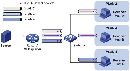
The IPv6 multicast VLAN feature configured on the Layer 2 device is the solution to this issue. With the IPv6 multicast VLAN feature, the Layer 3 device needs to replicate the multicast traffic only in the IPv6 multicast VLAN instead of making a separate copy of the multicast traffic in each user VLAN. This saves the network bandwidth and lessens the burden of the Layer 3 device.
The switch supports only sub-VLAN-based IPv6 multicast VLANs.
As shown in Figure 2, Host A, Host B and Host C are in three different user VLANs. On Switch A, configure VLAN 10 as an IPv6 multicast VLAN, configure all the user VLANs as sub-VLANs of this IPv6 multicast VLAN, and enable MLD snooping in the IPv6 multicast VLAN.
Figure 2 A sub-VLAN-based IPv6 multicast VLAN
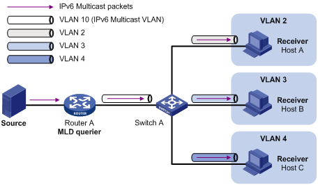
After the configuration, MLD snooping manages router ports in the IPv6 multicast VLAN and member ports in the sub-VLANs. When forwarding multicast data to Switch A, Router A needs to send only one copy of multicast traffic to Switch A in the IPv6 multicast VLAN, and Switch A distributes the traffic to the IPv6 multicast VLAN’s sub-VLANs that contain receivers.
|
|
NOTE: · For more information about MLD snooping, router ports, and member ports, see the chapter “Configuring MLD snooping.” · For more information about VLAN tags, see Layer 2—LAN Switching Configuration Guide. |
IPv6 multicast VLAN configuration task list
Complete the following tasks to configure IPv6 multicast VLAN:
|
Task |
Remarks |
|
Required |
|
|
Setting the maximum number of forwarding entries for IPv6 multicast VLANs |
Optional |
Configuring an IPv6 multicast VLAN
Configuration prerequisites
Before you configure sub-VLAN-based IPv6 multicast VLAN, complete the following tasks:
· Enable IPv6 forwarding.
· Create VLANs as required.
· Enable MLD snooping in the VLAN to be configured as an IPv6 multicast VLAN.
Configuring an IPv6 multicast VLAN
In this approach, you configure a VLAN as an IPv6 multicast VLAN, and configure user VLANs as sub-VLANs of the IPv6 multicast VLAN.
To configure a sub-VLAN-based IPv6 multicast VLAN:
|
Step |
Command |
Remarks |
|
1. Enter system view. |
system-view |
N/A |
|
2. Configure the specified VLAN as an IPv6 multicast VLAN and enter IPv6 multicast VLAN view. |
multicast-vlan ipv6 vlan-id |
No IPv6 multicast VLAN is configured by default. |
|
3. Assign the specified VLANs to the IPv6 multicast VLAN. |
subvlan vlan-list |
An IPv6 multicast VLAN has no sub-VLANs by default. |
|
|
NOTE: · You cannot configure an IPv6 multicast VLAN on a device with IP multicast routing enabled. · The VLAN to be configured as an IPv6 multicast VLAN must exist. · The VLANs to be configured as the sub-VLANs of the IPv6 multicast VLAN must exist. · An IPv6 multicast VLAN can have up to 1024 sub-VLANs. |
Setting the maximum number of forwarding entries for IPv6 multicast VLANs
You can set the maximum number of entries in the MLD snooping forwarding table for IPv6 multicast VLANs. When the number of forwarding entries maintained for the IPv6 multicast VLANs reaches the threshold, the device creates no more forwarding entries until some entries time out or are manually removed.
To set the maximum number of entries in the forwarding table:
|
Step |
Command |
Remarks |
|
1. Enter system view. |
system-view |
N/A |
|
2. Set the maximum number of forwarding entries for IPv6 multicast VLANs. |
multicast-vlan ipv6 entry-limit limit |
The default upper limit depends on the system working mode. For more information, see Fundamentals Configuration Guide. |
|
|
NOTE: If the number of existing entries in the MLD snooping forwarding table for the IPv6 multicast VLANs is larger than the limit when you configure it, the system informs you to remove excessive entries. In this case, the system does not automatically remove any existing entries or create new entries. |
Displaying and maintaining an IPv6 multicast VLAN
|
Task |
Command |
Remarks |
|
Display information about an IPv6 multicast VLAN. |
display multicast-vlan ipv6 [ vlan-id ] [ | { begin | exclude | include } regular-expression ] |
Available in any view |
IPv6 multicast VLAN configuration example
|
|
NOTE: By default, Ethernet interfaces, VLAN interfaces, and aggregate interfaces are in the state of DOWN. To configure such an interface, use the undo shutdown command to bring it up first. |
Network requirements
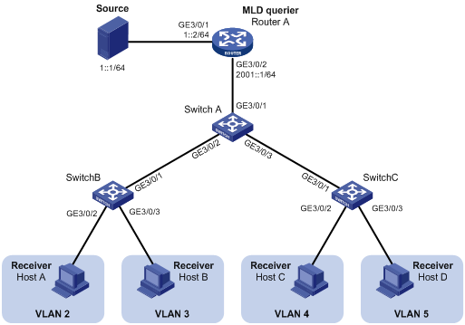
As shown in Figure 3, Router A connects to an IPv6 multicast source through GigabitEthernet 3/0/1 and to Switch A through GigabitEthernet 3/0/2. MLDv1 runs on Router A, and MLDv1 snooping runs on Switch A. Router A acts as the MLD querier.
The IPv6 multicast source sends IPv6 multicast data to the IPv6 multicast group FF1E::101. Host A, Host B, Host C, and Host D are receivers of the IPv6 multicast group. The hosts belong to VLAN 2 through VLAN 5 respectively.
Configure the sub-VLAN-based IPv6 multicast VLAN feature on Switch A so that Router A just sends IPv6 multicast data to Switch A through the IPv6 multicast VLAN and Switch A forwards the traffic to the receivers that belong to different user VLANs.
Configuration procedure
1. Enable IPv6 forwarding and configure IPv6 addresses:
Enable IPv6 forwarding on each device and configure an IPv6 address and address prefix for each interface as per Figure 3. (Details not shown)
2. Configure Router A:
# Enable IPv6 multicast routing, enable IPv6 PIM-DM on each interface and enable MLD on the host-side interface GigabitEthernet 3/0/2.
<RouterA> system-view
[RouterA] multicast ipv6 routing-enable
[RouterA] interface GigabitEthernet 3/0/1
[RouterA-GigabitEthernet3/0/1] pim ipv6 dm
[RouterA-GigabitEthernet3/0/1] quit
[RouterA] interface GigabitEthernet 3/0/2
[RouterA-GigabitEthernet3/0/2] pim ipv6 dm
[RouterA-GigabitEthernet3/0/2] mld enable
3. Configure Switch A:
# Enable MLD snooping globally.
<SwitchA> system-view
[SwitchA] mld-snooping
[SwitchA-mld-snooping] quit
# Create VLAN 2 through VLAN 5.
[SwitchA] vlan 2 to 5
# Configure GigabitEthernet 3/0/2 as a trunk port that permits packets from VLAN 2 and VLAN 3 to pass through.
[SwitchA] interface GigabitEthernet 3/0/2
[SwitchA-GigabitEthernet3/0/2] port link-type trunk
[SwitchA-GigabitEthernet3/0/2] port trunk permit vlan 2 3
[SwitchA-GigabitEthernet3/0/2] quit
# Configure GigabitEthernet 3/0/3 as a trunk port that permits packets from VLAN 4 and VLAN 5 to pass through.
[SwitchA] interface GigabitEthernet 3/0/3
[SwitchA-GigabitEthernet3/0/3] port link-type trunk
[SwitchA-GigabitEthernet3/0/3] port trunk permit vlan 4 5
[SwitchA-GigabitEthernet3/0/3] quit
# Create VLAN 10, assign GigabitEthernet 3/0/1 to this VLAN and enable MLD snooping in the VLAN.
[SwitchA] vlan 10
[SwitchA-vlan10] port GigabitEthernet 3/0/1
[SwitchA-vlan10] mld-snooping enable
[SwitchA-vlan10] quit
# Configure VLAN 10 as an IPv6 multicast VLAN and configure VLAN 2 through VLAN 5 as its sub-VLANs.
[SwitchA] multicast-vlan ipv6 10
[SwitchA-ipv6-mvlan-10] subvlan 2 to 5
[SwitchA-ipv6-mvlan-10] quit
4. Configure Switch B:
# Enable MLD snooping globally.
<SwitchB> system-view
[SwitchB] mld-snooping
[SwitchB-mld-snooping] quit
# Create VLAN 2, assign GigabitEthernet 3/0/2 to VLAN 2, and enable MLD snooping in the VLAN.
[SwitchB] vlan 2
[SwitchB-vlan2] port GigabitEthernet 3/0/2
[SwitchB-vlan2] mld-snooping enable
[SwitchB-vlan2] quit
# Create VLAN 3, assign GigabitEthernet 3/0/3 to VLAN 3, and enable MLD snooping in the VLAN.
[SwitchB] vlan 3
[SwitchB-vlan3] port GigabitEthernet 3/0/3
[SwitchB-vlan3] mld-snooping enable
[SwitchB-vlan3] quit
# Configure GigabitEthernet 3/0/1 as a trunk port that permits packets from VLAN 2 and VLAN 3 to pass through.
[SwitchB] interface GigabitEthernet 3/0/1
[SwitchB-GigabitEthernet3/0/1] port link-type trunk
[SwitchB-GigabitEthernet3/0/1] port trunk permit vlan 2 3
5. Configure Switch C:
The configurations required on Switch C are similar to those on Switch B.
6. Verify the configuration:
# Display information about the IPv6 multicast VLAN.
[SwitchA] display multicast-vlan ipv6
Total 1 IPv6 multicast-vlan(s)
IPv6 Multicast vlan 10
subvlan list:
vlan 2-5
# View the MLD snooping IPv6 multicast group information on Switch A.
[SwitchA] display mld-snooping group
Total 5 IP Group(s).
Total 5 IP Source(s).
Total 5 MAC Group(s).
Port flags: D-Dynamic port, S-Static port, C-Copy port, P-PIM port
Subvlan flags: R-Real VLAN, C-Copy VLAN
Vlan(id):2.
Total 1 IP Group(s).
Total 1 IP Source(s).
Total 1 MAC Group(s).
Router port(s):total 0 port(s).
IP group(s):the following ip group(s) match to one mac group.
IP group address:FF1E::101
(::, FF1E::101):
Host port(s):total 1 port(s).
GE3/0/2 (D)
MAC group(s):
MAC group address:3333-0000-0101
Host port(s):total 1 port(s).
GE3/0/2
Vlan(id):3.
Total 1 IP Group(s).
Total 1 IP Source(s).
Total 1 MAC Group(s).
Router port(s):total 0 port(s).
IP group(s):the following ip group(s) match to one mac group.
IP group address:FF1E::101
(::, FF1E::101):
Host port(s):total 1 port(s).
GE3/0/2 (D)
MAC group(s):
MAC group address:3333-0000-0101
Host port(s):total 1 port(s).
GE3/0/2
Vlan(id):4.
Total 1 IP Group(s).
Total 1 IP Source(s).
Total 1 MAC Group(s).
Router port(s):total 0 port(s).
IP group(s):the following ip group(s) match to one mac group.
IP group address:FF1E::101
(::, FF1E::101):
Host port(s):total 1 port(s).
GE3/0/3 (D)
MAC group(s):
MAC group address:3333-0000-0101
Host port(s):total 1 port(s).
GE3/0/3
Vlan(id):5.
Total 1 IP Group(s).
Total 1 IP Source(s).
Total 1 MAC Group(s).
Router port(s):total 0 port(s).
IP group(s):the following ip group(s) match to one mac group.
IP group address:FF1E::101
(::, FF1E::101):
Host port(s):total 1 port(s).
GE3/0/3 (D)
MAC group(s):
MAC group address:3333-0000-0101
Host port(s):total 1 port(s).
GE3/0/3
Vlan(id):10.
Total 1 IP Group(s).
Total 1 IP Source(s).
Total 1 MAC Group(s).
Router port(s):total 1 port(s).
GE3/0/1 (D)
IP group(s):the following ip group(s) match to one mac group.
IP group address:FF1E::101
(::, FF1E::101):
Host port(s):total 0 port(s).
MAC group(s):
MAC group address:3333-0000-0101
Host port(s):total 0 port(s).
The output shows that MLD snooping is maintaining the router port in the IPv6 multicast VLAN (VLAN 10) and the member ports in the sub-VLANs (VLAN 2 through VLAN 5).