- Table of Contents
- Related Documents
-
| Title | Size | Download |
|---|---|---|
| 01-Text | 1.26 MB |
Table of Contents
1.2 S3610-28TP Ethernet Switch
1.6 S3610-52M/S3610-52M-DC Ethernet Switch
1.7 S3610 Series Ethernet Switches System Features
Chapter 2 Installation Preparation
2.2.3 Electromagnetic Susceptibility
Chapter 3 Installing the Switch
3.1.1 Mounting a Switch to a Cabinet
3.1.2 Mounting a Switch on a Workbench
3.2 Connecting the Power Cord and the Ground Wire
3.2.1 Connecting the AC-Input Power Cord
3.2.2 Connecting the DC-Input Power Cord
3.2.3 Connecting the Ground Wire
3.3 Connecting the Switch to a Console Terminal
3.3.2 Connecting the Console Cable
3.4 Installation of the Optional Interface Modules
3.4.1 Installation of the Optional Interface Modules
3.4.2 Removal of Optional Interface Modules
Chapter 4 Starting up the Switch at the Initial Boot
4.1 Setting up a Configuration Environment
4.2 Connecting the Console Cable
4.3 Setting Terminal Parameters
4.4.1 Verifying Installation before Power-up
Chapter 5 Loading Boot ROM and Host Software
5.1 Introduction to Loading Approaches
5.2.2 Loading Software from Console Port Using XMODEM
5.2.3 Loading Software from an Ethernet Port Using TFTP
5.2.4 Loading Software from an Ethernet Port Using FTP
5.3.1 Loading Software Remotely Using FTP
5.3.2 Loading Software Remotely Using TFTP
Chapter 6 Maintenance and Troubleshooting
6.1 Dealing with Loading Failures
6.2 Dealing with Password Loss
6.2.1 Dealing with User Password Loss
6.2.2 Recovering the Boot ROM Password
6.3 Dealing with Power System Failures
6.4 Dealing with Configuration System Failures
Chapter 7 Optional Interface Modules
7.1 8-Port
100Base-FX Single Mode/Multi-Mode Module
7.1.2 Module Interface Optical Fiber
7.2 8-Port 10Base-T/100Base-TX
Module
7.3 8-Port 100
Mbps SFP Module Port Attributes.
Chapter 1 Product Overview
1.1 Introduction
H3C S3610 Series Ethernet Switches (hereinafter referred to as S3610 series) are wire speed Layer 2/3 Ethernet switches developed by H3C independently. They are intelligent network-manageable switches intended for network environments requiring high performance, dense port distribution, and ease of installation.
Table 1-1 lists the models in the S3610 series:
Table 1-1 Models in the S3610 series
|
Model |
Power supply |
Total service ports |
Number of 100 Mbps ports |
Number of 1000 Mbps uplink ports |
Console port |
|
S3610-28TP |
AC-input DC-input |
28 |
24 fixed 10Base-T/100Base-TX Ethernet ports |
2 × 1000 Mbps SFP ports 2 × 10/100/1000Base-T Ethernet ports |
One |
|
S3610-28P |
AC-input DC-input |
28 |
24 fixed 10Base-T/100Base-TX Ethernet ports |
4 × 1000 Mbps SFP ports |
One |
|
S3610-28F |
AC-input DC-input |
28 |
24 × 100 Mbps SFP ports |
2 × 1000 Mbps SFP ports 2 × 10/100/1000Base-T Ethernet ports |
One |
|
S3610-52P |
AC-input DC-input |
52 |
48 fixed 10Base-T/100Base-TX Ethernet ports |
4 × 1000 Mbps SFP ports |
One |
|
S3610-52M |
AC-input |
Depending on the inserted interface module, 52 at most. |
Depending on the inserted interface module, up to 48 10/100 Mbps electrical ports or 48 100 Mbps SFP ports |
4 × 1000 Mbps SFP ports 4 × 10/100/1000 Mbps electrical ports |
One |
|
S3610-52M-DC |
DC-input |
One |
1.2 S3610-28TP Ethernet Switch
1.2.1 Front Panel
I. Illustration
On its front panel, the S3610-28TP provides 24 fixed 10Base-T/100Base-TX Ethernet ports, two 1000 Mbps SFP ports, two 10/100/1000Base-T Ethernet ports and one console port, as shown in Figure 1-1.

|
(1) 100 Mbps
Ethernet port status LEDs |
(2) 1000 Mbps
SFP port status LEDs |
|
(3) 1000 Mbps
Ethernet port status LEDs |
(4) Console port |
|
(5) 7-segment numerical display |
(6) Port mode switch button |
|
(7) Port mode switch LED |
(8) Power LED |
|
(9) DC-input power LED |
|
Figure 1-1 Front panel of the S3610-28TP
II. LEDs
For your convenience to monitor the operation of the switch, the S3610-28TP provides one power LED, one DC-input power LED, one port mode switch LED, one 7-segment numerical display, 24 × 10/100 Mbps Ethernet port status LEDs, two 1000 Mbps SFP port status LEDs and two 10/100/1000 Mbps Ethernet port status LEDs on its front panel. Table 1-2 describes the meanings of these LEDs:
Table 1-2 LEDs on the front panel of the S3610-28TP
|
LED |
Mark |
Status |
Meaning |
||||
|
Port mode switch LED |
Mode |
Speed |
Solid green |
The port status LEDs are showing their current port speeds. |
|||
|
Duplex |
Solid yellow |
The port status LEDs are showing their current duplex modes. |
|||||
|
Host status LED |
SYS |
Solid green |
The switch works normally. |
||||
|
Flashing green (at 1 Hz) |
The switch is running power-on self-test (POST) or is loading software. (1) When running POST, The system displays the number of current POST item on the 7-segment numerical display LED, for example:
(2) When loading software, the system lights the short bars one after another in clockwise direction on the 7-segment numerical display LED:
|
||||||
|
Solid red |
The switch fan is in trouble. At this time, the system displays "F" on the 7-segment numerical display LED:
|
||||||
|
Flashing red |
The system fails the POST and does not work. At this time, the system displays the number of the failed POST item on the 7-segment numerical display LED, for example:
|
||||||
|
Flashing yellow (at 1 Hz) |
Some of the ports on the switch fails the POST and do not work. |
||||||
|
OFF |
The switch is powered off. |
||||||
|
DC-input power LED |
RPS |
Solid green |
The DC input and the AC part are all normal. |
||||
|
Solid yellow |
The DC input is normal; the AC part is abnormal or the AC input is disconnected. |
||||||
|
OFF |
The DC input is disconnected. |
||||||
|
7-segment numerical display |
Unit |
In the process of POST |
The number of current POST item is displayed.
|
||||
|
POST failure |
The number of the failed POST item is displayed.
|
||||||
|
Loading software |
The short bars are lighted one after another in clockwise direction during the loading.
|
||||||
|
Fan failure |
"F" is displayed.
|
||||||
|
10Base-T/100Base-TX
Ethernet port status LED |
— |
In speed mode |
Green |
The port works at 100 Mbps; when it receives/sends data, the LED flashes quickly. |
|||
|
Yellow |
The port works at 10 Mbps; when it receives/sends data, the LED flashes quickly. |
||||||
|
Flashing yellow (at 3 Hz) |
The port fails the POST. |
||||||
|
OFF |
The port is disconnected. |
||||||
|
In duplex mode |
Green |
The port works in full duplex mode; when it receives/sends data, the LED flashes quickly. |
|||||
|
Yellow |
The port works in half duplex mode; when it receives/sends data, the LED flashes quickly. |
||||||
|
Flashing yellow (at 3 Hz) |
The port fails the POST. |
||||||
|
OFF |
The port is disconnected. |
||||||
|
1000Base SFP port status LED |
— |
Speed |
Green |
The port works at 1000 Mbps; when it receives/sends data, the LED flashes quickly. |
|||
|
Flashing yellow (at 3 Hz) |
The port fails the POST. |
||||||
|
OFF |
The port is disconnected. |
||||||
|
Duplex |
Green |
The port works at 1000 Mbps in full duplex mode; when it receives/sends data, the LED flashes quickly. |
|||||
|
Flashing yellow (at 3 Hz) |
The port fails the POST. |
||||||
|
OFF |
The port is disconnected. |
||||||
|
10/100/1000Base-T
Ethernet port status LED |
— |
Speed |
Green |
The port works at 1000 Mbps; when it receives/sends data, the LED flashes quickly. |
|||
|
Yellow |
The port works at 10/100 Mbps; when it receives/sends data, the LED flashes quickly. |
||||||
|
Flashing yellow (at 3 Hz) |
The port fails the POST. |
||||||
|
OFF |
The port is disconnected. |
||||||
|
Duplex |
Green |
The port works in full duplex mode; when it receives/sends data, the LED flashes quickly. |
|||||
|
Yellow |
The port works in half duplex mode; when it receives/sends data, the LED flashes quickly. |
||||||
|
Flashing yellow (at 3 Hz) |
The port fails the POST. |
||||||
|
OFF |
The port is disconnected. |
||||||
III. Fixed 10Base-T/100Base-TX Ethernet ports
The following table describes the attributes of the 10Base-T/100Base-TX Ethernet ports.
Table 1-3 Attributes of the 10Base-T/100Base-TX Ethernet ports
|
Item |
Description |
|
Connector |
RJ-45 |
|
Number of ports |
24 |
|
Speed and mode |
10 Mbps, full/half duplex 100 Mbps, full/half duplex |
|
Standard |
IEEE 802.3u |
|
Medium and transmission distance |
Category-5 twisted pair, 100 m (328.1 ft.) |
IV. 1000 Mbps SFP ports
The S3610-28TP provides two 1000 Mbps SFP ports (No. 25 and 26) on its front panel, each of which can be connected with an SFP optical interface module or an SFP electrical interface module.
The available SFP modules are hot-swappable and multifarious. This brings flexibility to your actual networking.
You can choose the following SFP modules as required.
Table 1-4 Available 1000 Mbps SFP modules
|
Item |
Specific model |
|
Gigabit SFP optical module |
l SFP-GE-SX-MM850-A l SFP-GE-LX-SM1310-A l SFP-GE-LH40-SM1310 l SFP-GE-LH40-SM1550 l SFP-GE-LH70-SM1550 |
|
100 Mbps SFP optical module |
l SFP-FE-SX-MM1310-A l SFP-FE-LX-SM1310-A l SFP-FE-LH40-SM1310 l SFP-FE-LH80-SM1550 |
|
Gigabit BIDI module |
l SFP-GE-LX-SM1310-BIDI l SFP-GE-LX-SM1490-BIDI |
|
100 Mbps BIDI module |
l SFP-FE-LX-SM1310-BIDI l SFP-FE-LX-SM1550-BIDI |
|
SFP electrical module |
SFP-GE-T |
& Note:
l For specifications of each SFP module, refer to H3C Low-End Series Ethernet Switches Pluggable Module Manual.
l The available SFP modules may change as time goes by. Contact the H3C marketing or technical support personnel for the latest available SFP modules.
l The 1000 Mbps/100 Mbps BIDI modules will be supported in Release 5303 and later version.
V. Fixed 10/100/1000Base-T Ethernet ports
The S3610-28TP provides two 10/100/1000Base-T Ethernet ports (No. 27 and 28) on its front panel. The following table describes the attributes of these ports:
Table 1-5 Attributes of the 10/100/1000Base-T Ethernet ports
|
Item |
Description |
|
Connector |
RJ-45 |
|
Number of the ports |
Two |
|
Speed and mode |
10/100 Mbps full/half duplex 1000 Mbps full duplex MDI/MDI-X auto negotiation |
|
Standard |
IEEE 802.3u IEEE 802.3ab |
|
Medium and transmission distance |
Category-5 twisted pair, 100 m (328.1 ft.) |
VI. Console port
The S3610-28TP provides a console port that is compliant with the EIA/TIA-232 asynchronous serial interface standard. You can use this port to configure the switch locally or remotely.
Table 1-6 Attributes of the console port
|
Item |
Description |
|
Connector |
RJ-45 |
|
Standard |
Asynchronous EIA/TIA-232 |
|
Baud rate |
9600 bit/s by default |
|
Service |
Connection with a character terminal Connection with the serial interface of a local terminal (a PC for example) or a remote terminal (through a pair of modems), on which a terminal emulation program is running |
1.2.2 Rear Panel
The S3610-28TP has an AC-input power socket, a DC-input power socket, and a grounding screw on its rear panel, as shown in Figure 1-2.

|
(1) AC-input power socket |
(2) DC-input power socket |
(3) Grounding screw |
Figure 1-2 Rear panel of the S3610-28TP
1.2.3 Power Supply System
I. AC-input voltage range
Rated voltage range: 100 VAC to 240 VAC, 50 Hz or 60 Hz
Max voltage range: 90 VAC to 264 VAC, 50 Hz or 60 Hz
II. DC-input voltage range
Rated voltage range: –48 VDC to –60 VDC
Max voltage range: –36 VDC to –72 VDC
1.3 S3610-28P Ethernet Switch
1.3.1 Front Panel
I. Illustration
On its front panel the S3610-28P provides 24 fixed autosensing 10Base-T/100Base-TX Ethernet ports, four 1000 Mbps SFP ports and one console port, as shown in Figure 1-3.

|
(1) 100 Mbps Ethernet port status LEDs |
(2) 1000 Mbps SFP port status LEDs |
|
(3) Console port |
(4) 7-segment numerical display |
|
(5) Port mode switch button |
(6) Port mode switch LED |
|
(7) Power LED |
(8) DC-input power LED |
Figure 1-3 Front panel of the S3610-28P
II. LEDs
For your convenience to monitor the operation of the switch, the S3610-28P provides one power LED, one DC-input power LED, one port mode switch LED, one 7-segment numerical display, 24 × 10/100 Mbps Ethernet port status LEDs, and four 1000 Mbps SFP port status LEDs on its front panel. Table 1-7 describes the meanings of these LEDs:
Table 1-7 LEDs on the front panel of the S3610-28P
|
LED |
Mark |
Status |
Meaning |
||
|
Port mode switch LED |
Mode |
Speed |
Solid green |
The port status LEDs are showing their current port speeds. |
|
|
Duplex |
Solid yellow |
The port status LEDs are showing their current duplex modes. |
|||
|
Power LED |
PWR |
Solid green |
The switch works normally. |
||
|
Flashing green (at 1 Hz) |
The switch is running power-on self-test (POST) or is loading software. (1) When running POST, The system displays the number of current POST item on the 7-segment numerical display LED, for example:
(2) When loading software, the system lights the short bars one after another in clockwise direction on the 7-segment numerical display LED:
|
||||
|
Solid red |
The switch fan is in trouble. At this time, the system displays "F" on the 7-segment numerical display LED:
|
||||
|
Flashing red |
The system fails the POST and does not work. At this time, the system displays the number of the failed POST item on the 7-segment numerical display LED, for example:
|
||||
|
Flashing yellow (at 1 Hz) |
Some of the ports fails the POST and do not work. |
||||
|
OFF |
The switch is powered off. |
||||
|
DC-input power LED |
RPS |
Solid green |
The DC input and the AC part are all normal. |
||
|
Solid yellow |
The DC input is normal; the AC part is abnormal or the AC input is disconnected. |
||||
|
OFF |
The DC input is disconnected. |
||||
|
7-segment numerical display |
Unit |
In the progress of POST |
The number of current POST item is displayed.
|
||
|
POST failure |
The number of failed POST item is displayed.
|
||||
|
Loading software |
The short lines are lighted clockwise during the loading.
|
||||
|
Fan failure |
"F" is displayed.
|
||||
|
10Base-T/100Base-TX Ethernet port status
LED |
— |
Speed |
Green |
The port works at 100 Mbps; when it receives/sends data, the LED flashes quickly. |
|
|
Yellow |
The port works at 10 Mbps; when it receives/sends data, the LED flashes quickly. |
||||
|
Flashing yellow (at 3 Hz) |
The port fails the POST. |
||||
|
OFF |
The port is disconnected. |
||||
|
Duplex |
Green |
The port works in full duplex mode; when it receives/sends data, the LED flashes quickly. |
|||
|
Yellow |
The port works in half duplex mode; when it receives/sends data, the LED flashes quickly. |
||||
|
Flashing yellow (at 3 Hz) |
The port fails the POST. |
||||
|
OFF |
The port is disconnected. |
||||
|
1000Base SFP port status LED |
— |
Speed |
Green |
The port works at 1000 Mbps; when it receives/sends data, the LED flashes quickly. |
|
|
Flashing yellow (at 3 Hz) |
The port fails the POST. |
||||
|
OFF |
The port is disconnected. |
||||
|
Duplex |
Green |
The port works at 1000 Mbps in full duplex mode; when it receives/sends data, the LED flashes quickly. |
|||
|
Flashing yellow (at 3 Hz) |
The port fails the POST. |
||||
|
OFF |
The port is disconnected. |
||||
III. Fixed 10Base-T/100Base-TX Ethernet ports
For the attributes of the 10Base-T/100Base-TX Ethernet ports, see Table 1-3.
IV. 1000 Mbps SFP ports
The S3610-28P provides up to four 1000 Mbps SFP ports on its front panel. You can determine the number and the types of the ports according to your needs.
The SFP modules that can be connected with the ports are hot-swappable and multifarious. This brings flexibility to your actual networking.
You can choose the SFP modules listed in Table 1-4 as required.
& Note:
l For specifications of each SFP module, refer to H3C Low-End Series Ethernet Switches Pluggable Module Manual.
l The available SFP modules may change as time goes by. Contact the H3C marketing or technical support personnel for the latest available SFP modules.
V. Console port
The S3610-28P provides an EIA/TIA-232-compliant console port. You can use this port to configure the switch locally or remotely. See Table 1-6 for the attributes of the console port.
1.3.2 Rear Panel
The S3610-28P has an AC-input power socket, a DC-input power socket, and a grounding screw on its rear panel, as shown in Figure 1-4.

|
(1) AC-input power socket |
(2) DC-input power socket |
(3) Grounding screw |
Figure 1-4 Rear panel of the S3610-28P
1.3.3 Power Supply System
I. AC-input voltage range
Rated voltage range: 100 VAC to 240 VAC, 50 Hz or 60 Hz
Max voltage range: 90 VAC to 264 VAC, 50 Hz or 60 Hz
II. DC-input voltage range
Rated voltage range: –48 VDC to –60 VDC
Max voltage range: –36 VDC to –72 VDC
1.4 S3610-28F Ethernet Switch
1.4.1 Front Panel
I. Illustration
On its front panel the S3610-28F provides 24 × 100 Mbps SFP ports, two 1000 Mbps SFP ports, two 10/100/1000Base-T Ethernet ports and one console port, as shown in Figure 1-5.

|
(1) 100 Mbps SFP port status LEDs |
(2) 1000 Mbps SFP port status LEDs |
|
(3) 1000 Mbps Ethernet port status LEDs |
(4) Console port |
|
(5) 7-segment numerical display |
(6) Port mode switch button |
|
(7) Port mode switch LED |
(8) Power LED |
|
(9) DC-input power LED |
|
Figure 1-5 Front panel of the S3610-28F
II. LEDs
For your convenience to monitor the operation of the switch, the S3610-28F provides one power LED, one DC-input power LED, one port mode switch LED, one 7-segment numerical display, 24 × 100 Mbps SFP port status LEDs, two 1000 Mbps SFP port status LEDs, and two 1000 Mbps Ethernet port status LEDs on its front panel. Table 1-8 describes the meanings of these LEDs.
Table 1-8 LEDs on the front panel of the S3610-28F
|
LED |
Mark |
Status |
Meaning |
||||
|
Port mode switch LED |
Mode |
Speed |
Solid green |
The port status LEDs are showing their current port speeds. |
|||
|
Duplex |
Solid yellow |
The port status LEDs are showing their current duplex modes. |
|||||
|
Power LED |
PWR |
Solid green |
The switch works normally. |
||||
|
Flashing green (at 1 Hz) |
The switch is running power-on self-test (POST) or is loading software. (1) When running POST, The system displays the number of current POST item on the 7-segment numerical display LED, for example:
(2) When loading software, the system lights the short bars one after another in clockwise direction on the 7-segment numerical display LED:
|
||||||
|
Solid red |
The switch fan is in trouble. At this time, the system displays "F" on the 7-segment numerical display LED:
|
||||||
|
Flashing red |
The system fails the POST and does not work. At this time, the system displays the number of the failed POST item on the 7-segment numerical display LED, for example:
|
||||||
|
Flashing yellow (at 1 Hz) |
Some of the ports fails the POST and do not work. |
||||||
|
OFF |
The switch is powered off. |
||||||
|
DC-input power LED |
RPS |
Solid green |
The DC input and the AC part are all normal. |
||||
|
Solid yellow |
The DC input is normal; the AC part is abnormal or the AC input is disconnected. |
||||||
|
OFF |
The DC input is disconnected. |
||||||
|
7-segment numerical display |
Unit |
In the progress of POST |
The number of current POST item is displayed.
|
||||
|
POST failure |
The number of failed POST item is displayed.
|
||||||
|
Loading software |
The short lines are lighted clockwise during the loading.
|
||||||
|
Fan failure |
"F" is displayed.
|
||||||
|
100Base SFP port status LED |
— |
Speed |
Green |
The port works at 100 Mbps; when it receives/sends data, the LED flashes quickly. |
|||
|
Flashing yellow (at 3 Hz) |
The port fails the POST. |
||||||
|
OFF |
The port is disconnected. |
||||||
|
Duplex |
Green |
The port works at 100 Mbps in full duplex mode; when it receives/sends data, the LED flashes quickly. |
|||||
|
Flashing yellow (at 3 Hz) |
The port fails the POST. |
||||||
|
OFF |
The port is disconnected. |
||||||
|
1000Base SFP port status LED |
— |
Speed |
Green |
The port works at 1000 Mbps; when it receives/sends data, the LED flashes quickly. |
|||
|
Flashing yellow (at 3 Hz) |
The port fails the POST. |
||||||
|
OFF |
The port is disconnected. |
||||||
|
Duplex |
Green |
The port works at 1000 Mbps in full duplex mode; when it receives/sends data, the LED flashes quickly. |
|||||
|
Flashing yellow (at 3 Hz) |
The port fails the POST. |
||||||
|
OFF |
The port is disconnected. |
||||||
|
10/100/1000Base-T Ethernet port status
LED |
— |
Speed |
Green |
The port works at 1000 Mbps; when it receives/sends data, the LED flashes quickly. |
|||
|
Yellow |
The port works at 10/100 Mbps; when it receives/sends data, the LED flashes quickly. |
||||||
|
Flashing yellow (at 3 Hz) |
The port fails the POST. |
||||||
|
OFF |
The port is disconnected. |
||||||
|
Duplex |
Green |
The port works in full duplex mode; when it receives/sends data, the LED flashes quickly. |
|||||
|
Yellow |
The port works in half duplex mode; when it receives/sends data, the LED flashes quickly. |
||||||
|
Flashing yellow (at 3 Hz) |
The port fails the POST. |
||||||
|
OFF |
The port is disconnected. |
||||||
III. 100 Mbps SFP ports
The S3610-28F provides 24 × 100 Mbps SFP ports (No. 1 to 24) on its front panel, each of which can be connected with an SFP module.
The available SFP modules are hot-swappable and multifarious. This brings flexibility to your actual networking.
You can choose the following SFP modules as required.
Table 1-9 Available 100 Mbps SFP modules
|
Item |
Specific model |
|
100 Mbps SFP optical module |
l SFP-FE-SX-MM1310-A l SFP-FE-LX-SM1310-A l SFP-FE-LH40-SM1310 l SFP-FE-LH80-SM1550 |
|
100 Mbps BIDI module |
l SFP-FE-LX-SM1310-BIDI l SFP-FE-LX-SM1550-BIDI |
& Note:
l For specifications of each SFP module, refer to H3C Low-End Series Ethernet Switches Pluggable Module Manual.
l The available SFP modules may change as time goes by. Contact the H3C marketing or technical support personnel for the latest available SFP modules.
IV. 1000 Mbps SFP ports
The S3610-28F provides two 1000 Mbps SFP ports (No. 25 and 26) on its front panel, each of which can be connected with an SFP optical interface module or an SFP electrical interface module.
The available SFP modules are hot-swappable and multifarious. This brings flexibility to your actual networking.
You can choose the SFP modules listed in Table 1-4 as required.
V. Fixed 10/100/1000Base-T Ethernet ports
The S3610-28F provides two 10/100/1000Base-T Ethernet ports (No. 27 and 28) on its front panel. For the attributes of these ports, see Table 1-5.
VI. Console port
The S3610-28F provides an EIA/TIA-232-compliant console port. You can use this port to configure the switch locally or remotely. See Table 1-6 for the attributes of the console port.
1.4.2 Rear Panel
The S3610-28F has an AC-input power socket, a DC-input power socket, and a grounding screw on its rear panel, as shown in Figure 1-6.

|
(2) DC-input power socket |
(3) Grounding screw |
Figure 1-6 Rear panel of the S3610-28F
1.4.3 Power Supply System
I. AC-input voltage range
Rated voltage range: 100 VAC to 240 VAC, 50 Hz or 60 Hz
Max voltage range: 90 VAC to 264 VAC, 50 Hz or 60 Hz
II. DC-input voltage range
Rated voltage range: –48 VDC to –60 VDC
Max voltage range: –36 VDC to –72 VDC
1.5 S3610-52P Ethernet Switch
1.5.1 Front Panel
I. Illustration
On its front panel the S3610-52P provides 48 fixed autosensing 10Base-T/100Base-TX Ethernet ports, four 1000 Mbps SFP ports and one console port, as shown in Figure 1-7.

|
(1) 100 Mbps Ethernet port status LEDs |
(2) Console port |
|
(3) 7-segment numerical display |
(4) Port mode switch button |
|
(5) Port mode switch LED |
(6) Power LED |
|
(7) DC-input power LED |
(8) 1000 Mbps SFP port status LEDs |
Figure 1-7 Front panel of the S3610-52P
II. LEDs
For your convenience to monitor the operation of the switch, the S3610-52P provides one power LED, one DC-input power LED, one port mode switch LED, one 7-segment numerical display, 48 × 10/100 Mbps Ethernet port status LEDs, and four 1000 Mbps SFP port status LEDs on its front panel. See Table 1-7 for the meanings of these LEDs.
III. Fixed 10Base-T/100Base-TX Ethernet Ports
For the attributes of the 10Base-T/100Base-TX Ethernet ports, see Table 1-3.
IV. 1000 Mbps SFP ports
The S3610-52P provides up to four 1000 Mbps SFP ports on its front panel. You can determine the number and the types of the ports according to your needs.
SFP modules that can be connected with the ports are hot-swappable and multifarious. This brings flexibility to your actual networking.
You can choose the SFP modules listed in Table 1-4 as required.
& Note:
l For specifications of each SFP module, refer to H3C Low-End Series Ethernet Switches Pluggable Module Manual.
l The available SFP modules may change as time goes by. Contact the H3C marketing or technical support personnel for the latest available SFP modules.
V. Console port
The S3610-52P provides an EIA/TIA-232-compliant console port. You can use this port to configure the switch locally or remotely. See Table 1-6 for the attributes of the console port.
1.5.2 Rear Panel
The S3610-52P has an AC-input power socket, a DC-input power socket, and a grounding screw on its rear panel, as shown in Figure 1-8.

|
(2) DC-input power socket |
(3) Grounding screw |
Figure 1-8 Rear panel of the S3610-52P
1.5.3 Power Supply System
I. AC-input voltage range
Rated voltage range: 100 VAC to 240 VAC, 50 Hz or 60 Hz
Max voltage range: 90 VAC to 264 VAC, 50 Hz or 60 Hz
II. DC-input voltage range
Rated voltage range: –48 VDC to –60 VDC
Max voltage range: –36 VDC to –72 VDC
1.6 S3610-52M/S3610-52M-DC Ethernet Switch
1.6.1 Front Panel
I. Illustration
& Note:
S3610-52M and S3610-52M-DC switches have the same front panels. The following takes the front panel of S3610-52M switch as an example.
On its front panel, the S3610-52M/S3610-52M-DC switch provides six slots where you can insert the 8-port 100 Mbps single-mode/multimode modules, 8-port 10Base-T/100Base-TX modules, and 8-port 100 Mbps SFP modules as needed. The following figure illustrates the front panel with all the six slots inserted with 8-port 100 Mbps single-mode modules:

|
(1) Power LED |
Figure 1-9 Front panel of the S3610-52M
![]() Caution:
Caution:
The interface modules on the front panel of the H3C S3610-52M and S3610-52M-DC are not hot-swappable. To install or remove these modules, you must first power off the switch. For how to install and remove these modules, refer to section 3.4 "Installation of the Optional Interface Modules”.
II. LED
The S3610-52M/S3610-52M-DC switch provides one power LED only on the front panel. After you insert an interface module in a slot, you can know the port working status based on the LEDs on the interface module. For description on the LEDs of the interface modules, refer to Chapter 7 “Optional Interface Modules” in page 7-1.
III. Interface modules
l
8-port
100Base-FX multimode module
l
8-port
100Base-FX single-mode module
l
8-port
10Base-T/100Base-TX module
l 8-port 100 Mbps SFP module
& Note:
For specific description on the interface modules, refer to Chapter 7 “Optional Interface Modules” in page 7-1.
IV. Console port
The S3610-52M/S3610-52M-DC switch provides an EIA/TIA-232-compliant console port. You can use this port to configure the switch locally or remotely. See Table 1-6 for the attributes of the console port.
1.6.2 Rear Panel
I. Rear panel of the S3610-52M switch
The rear panel of the S3610-52M switch is illustrated by the following figure. On the rear panel, there are grounding screw, AC-input power socket, RPS DC-input redundancy power socket, and the fixed interface module.

|
(1) Grounding screw |
(2) AC-input power socket |
|
(3) RPS DC-input redundancy power socket |
(4) Fixed interface module |
Figure 1-10 Rear panel of the S3610-52M
Rated voltage range: 100 VAC to 240 VAC; 50 Hz or 60 Hz
Max voltage range: 90 VAC to 264 VAC, 50 Hz or 60 Hz
II. Rear panel of the S3610-52M-DC switch
The rear panel of the S3610-52M-DC switch is illustrated by the following figure. On the rear panel, there are grounding screw, DC-input power socket, RPS DC-input redundancy power socket, and the fixed interface module.

|
(1) Grounding screw |
(2) DC-input power socket |
|
(3) RPS DC-input redundancy power socket |
(4) Fixed interface module |
Figure 1-11 Rear panel of the S3610-52M-DC
Rated voltage range: –48 VDC to –60 VDC
Max voltage range: –36 VDC to –72 VDC
III. Fixed interface module
On the rear panel of the S3610-52M/S3610-52M-DC switch, there is a fixed interface module that cannot be uninstalled. On the interface module, there are four Gigabit SFP ports and four 10/100/1000 Mbps Ethernet ports. An SFP port and an Ethernet port form a Combo port, and only one of the two ports forming a Combo port takes effect at a time.
The corresponding relationship between the SFP ports and Ethernet ports that form a Combo port are listed in the following table:
Table 1-10 Combo port list
|
SFP port |
Ethernet port |
|
49 |
53 |
|
50 |
54 |
|
51 |
55 |
|
52 |
56 |
The supported SFP modules for the fixed interface module are listed in Table 1-4.
1.7 S3610 Series Ethernet Switches System Features
Table 1-11 S3610 series Ethernet switches system features
|
Item |
H3C S3610 series |
||
|
Physical dimensions (H × W × D) |
S3610-52P |
43.6 × 440 × 260 mm (1.7 × 17.3 × 10.2 in.) |
|
|
S3610-28P |
|||
|
S3610-28TP |
|||
|
S3610-28F |
|||
|
S3610-52M/S3610-52M-DC |
86 × 440 × 420 mm (3.4 × 17.2 × 16.5 in.) |
||
|
Weight |
S3610-52P |
3.8 kg (8.4 lb.) |
|
|
S3610-28P |
3.6 kg (7.9 lb.) |
||
|
S3610-28TP |
3.7 kg (8.2 lb.) |
||
|
S3610-28F |
3.8 kg (8.4 lb.) |
||
|
S3610-52M/S3610-52M-DC |
8.5 kg (18.7 lb.) |
||
|
Management port |
One console port |
||
|
Service port |
S3610-28P |
24 × 10/100 Mbps electrical ports and 4 × 1000 Mbps SFP ports |
|
|
S3610-28TP |
24 × 10/100 Mbps electrical ports, 2 × 1000 Mbps SFP ports and 2 × 10/100/1000 Mbps electrical ports |
||
|
S3610-52P |
48 × 10/100 Mbps electrical ports and 4 x 1000 Mbps SFP ports |
||
|
S3610-28F |
24 × 100 Mbps SFP ports, 2 x 1000 Mbps SFP ports and 2 x 10/100/1000 Mbps electrical ports |
||
|
S3610-52M/S3610-52M-DC |
Decided by the inserted modules. Up to 48 × 10/100 Mbps electrical ports or 48 × 100 Mbps SFP ports. On the rear panel, there are 4 × 1000 Mbps fixed SFP ports and 4 × 10/100/1000 Mbps fixed electrical ports. |
||
|
Input voltage |
The S3610 series supports both AC input and DC input. AC input: Rated voltage range: 100 VAC to 240 VAC; 50 Hz or 60 Hz Max voltage range: 90 VAC to 264 VAC; 50 Hz or 60 Hz DC input: Rated voltage range: –48 VDC to –60 VDC Max voltage range: –36 VDC to –72 VDC |
||
|
Power consumption (fully loaded) |
S3610-52P |
45 W |
|
|
S3610-28P |
35 W |
||
|
S3610-28TP |
40 W |
||
|
S3610-28F |
60 W |
||
|
S3610-52M/S3610-52M-DC |
110 W |
||
|
Operating temperature |
0°C to 45°C (32°F to 113°F) |
||
|
Relative humidity (noncondensing) |
10% to 90% |
||
Chapter 2 Installation Preparation
2.1 Safety Precautions
To avoid any device impairment and bodily injury caused by improper use, observe these rules:
l Before cleaning the switch, unplug the power plug of the switch first. Do not clean the switch with wet cloth or liquid.
l Do not place the switch near water or any damp area. Prevent water or moisture from entering the switch chassis.
l Do not place the switch on an unstable case or desk. The switch might be damaged severely in case of a fall.
l Ensure proper ventilation of the equipment room and keep the ventilation vents of the switch free of obstruction.
l Make sure that the operating voltage is the same one labeled on the switch.
l Do not open the chassis while the switch is operating or when electrical hazards are present to avoid electrical shocks.
l When replacing interface cards, wear ESD-protective gloves to avoid damaging the cards.
2.2 Installation Site
The S3610 series must be used indoors. You can mount your switch in a rack or on a tabletop/workbench, but make sure:
l Adequate clearance is reserved at the air inlet/exhaust vents for ventilation.
l The rack or table/workbench has a good ventilation system.
l The rack is sturdy enough to support the device and its accessories.
l The rack or table/workbench is well earthed.
To ensure normal operation and long service life of your VG, install it in an environment that meets the requirements described in the following subsections.
2.2.1 Temperature/Humidity
You must maintain a proper temperature and humidity in the equipment room. Refer to Table 1-11. Long-term high humidity may lead to bad insulation, electricity leakage, mechanical property changes, and corrosion. However, if the relative humidity is two low, captive screws may become loose as the result of contraction of insulation washers and static electricity may be produced in a dry environment to jeopardize the CMOS circuits on the device. High temperature is the most undesirable condition, because it accelerates aging of insulation materials and can thus significantly lower reliability and service life of your switch.
2.2.2 Cleanness
Dust is a hazard to the operating safety of your device. The dust accumulated on the chassis can be adsorbed by static electricity and result in poor contact of metal connectors or metal contact points. This can not only shorten the service life of your device but also cause communications failures. When the relative indoor humidity is low, electrostatic adsorption is more likely to happen. The contents of the dust must be limited as shown in the following table:
Table 2-1 Dust content limits in an equipment room
|
Substance |
Unit |
Content |
|
Dust |
Particles/m³ |
≤ 3 × 10⁴ (No visible dust on the tabletop for three days) |
|
Remark: the diameter of a dust particle ≥ 5 μm |
||
Besides dust, there are rigorous limits on the harmful gases that can accelerate the erosion and aging of metals, such as salts, acids, and sulfides, as shown in the following table.
Table 2-2 Harmful gas limits in the equipment room
|
Gas |
Maximum (mg/m3) |
|
SO2 |
0.2 |
|
H2S |
0.006 |
|
NH3 |
0.05 |
|
Cl2 |
0.01 |
2.2.3 Electromagnetic Susceptibility
The operation of your switch can be affected by external interferences, such as conducted emission by capacitance coupling, inductance coupling, electromagnetic wave radiation, and common impedance (including the grounding system) coupling, and leads (power cords, signaling cables and output wires. To eliminate the interferences, make sure to:
l For the AC power supply that adopts TN system, use a monophase three-line power socket with Protection Earth (PE) to effectively filter interference from the power grid.
l Keep the device far from radio transmitting stations, radar stations, and high-frequency devices.
l Use electromagnetic shielding when necessary, for example, use shielded interface cables.
l Route interface cables only indoors to prevent signal ports from getting damaged by overvoltage or overcurrent caused by lightning strikes.
2.2.4 Laser Safety
The S3610 series are class-1 laser devices.
When the optical ports on your switch are operating, do not stare into the optical ports because the laser light emitted by the optical fiber can hurt your retina.
![]() Caution:
Caution:
Staring into the laser beam produced by the fiber can hurt your eyes.
2.3 Installation Tools
l Flat-blade screwdriver
l Phillips screwdriver
l ESD-preventive wrist strap
![]() Caution:
Caution:
Chapter 3 Installing the Switch
![]() Caution:
Caution:
When you ask your sales agent to maintain the switch, you must ensure that the H3C dismantlement-preventive seal on a mounting screw of the switch chassis is intact. If you want to open the chassis, you should contact the agent for permission. Otherwise, you will bear any consequence resulted from your actions without permission.
3.1 Installing a Switch
3.1.1 Mounting a Switch to a Cabinet
You can install a switch into a 19-inch standard cabinet in one of the following three ways:
l Use front mounting ears
l Use front mounting ears and a tray
l Use front mounting ears and guide rails
& Note:
l The front mounting ears are provided in the standard package, while trays and guide rails are optional parts that you need to order as needed.
l When the switch is more than 300 mm (11.81 in.) in width, the front mounting ears are not used for bearing but for fixing only.
l When installing devices, ensure a clearance of 1U (44.45 mm, namely, 1.75 inches) between devices for heat dissipation.
l The guide rails provided by H3C are suitable for H3C 1000 mm (39.37 in.) standard cabinets only. If the depth of your cabinet does not fit, use other supports to replace the guide rails.
I. Introduction to mounting ear
Figure 3-1 shows the appearance of a front mounting ear.
|
(1) Screw hole used to fix the mounting ear to the cabinet (Use one M6 screw) |
|
(2) Screw hole used to fix the switch to the mounting ear |
Figure 3-1 Appearance of a standard front mounting ear
II. Introduction to guide rail
Figure 3-2 shows the appearance of a guide rail.

|
Slotted hole 1: Used to fix the guide rail to the rear bracket. You can adjust the screw hole position according to the position of the switch. |
|
Cooling hole: Used for heat dissipation between switch and cabinet |
|
Slotted hole 2: Used to fix the guide rail to the front bracket |
Figure 3-2 Appearance of a guide rail
III. Use front mounting ears to install a switch
& Note:
When installing the S3610-52M/S3610-52M-DC switch, you cannot use the front mounting ears only, but use the front mounting ears in conjunction with a tray or guide rails.
Follow these steps to mount a switch into a 19-inch standard cabinet:
1) Wear an ESD-preventive wrist strap to check the grounding and stability of the cabinet.
2) Take out the screws which are packed together with the front mounting ears, and fix one end of mounting ears to the switch, as shown in Figure 3-3.
Figure 3-3 Fix front mounting ears (1)
3) Place the switch horizontally in a proper position, and fix the other end of mounting ears to the front brackets with screws and captive nuts, as shown in Figure 3-4.
Figure 3-4 Fix front mounting ears (2)
IV. Use front mounting ears and a tray
Follow these steps to install a switch into a 19-inch standard cabinet:
1) Wear an ESD-preventive wrist strap to check the grounding and stability of the cabinet.
2) Fix the delivered tray horizontally in a proper position.
3) Take out the screws which are packed together with the front mounting ears, and fix one end of mounting ears to the switch, as shown in Figure 3-3.
Place the switch on the tray horizontally, slide the tray into the cabinet, and fix the other end of mounting ears to the front brackets with crews and captive nuts, as shown in Figure 3-4.
V. Use front mounting ears and guide rails
Follow these steps to install a switch into a 19-inch standard cabinet:
1) Wear an ESD-preventive wrist strap to check the grounding and stability of the cabinet.
2) Take out the screws packed together with the front mounting ears and fix one end of the front mounting ears to the switch, as shown in Figure 3-3.
3) Install guide rails on the brackets on both sides of the cabinet with M5 self-tapping screws, as shown in Figure 3-5.
Figure 3-5 Install guide rails
4) Hold the two sides of the switch and slide it gently along the guide rails into the cabinet until it is located in a proper position, as shown in Figure 3-6. Ensure that the bottom side of the guide rails and the switch are in close contact.
Figure 3-6 Install front mounting ears and guide rails
5) Fix the other end of front mounting ears to the front brackets of the cabinet with M6 screws and captive nuts and ensure that the front mounting ears and guide rails have fixed the switch in the cabinet securely, as shown in Figure 3-7.
Figure 3-7 Effect diagram of front mounting ear and guide rail installation
3.1.2 Mounting a Switch on a Workbench
In many cases, 19-inch standard cabinets
are not available. Therefore, switches are often installed on clean
workbenches. To install your switch on a workbench, you simply need to:
l Make sure that the workbench is flat and sturdy and well earthed.
l Leave a clearance of 10 cm (3.94 in.) around the device for heat dissipation.
l Do not lay heavy objects on the switch.
3.2 Connecting the Power Cord and the Ground Wire
3.2.1 Connecting the AC-Input Power Cord
I. AC-input power socket (recommended)
You are recommended to use a monophase three-line power socket with a ground contact or a general purpose PC power socket, making sure that the power point is well connected to building ground. Normally, the ground point of the power source in a building was buried in the ground during the construction and wiring. Still, you must make sure of that.
Figure 3-8 Power socket (recommended)
II. Connecting the AC-input power cord
Step 1: Connect one end of the chassis ground wire to the grounding screw on the rear of the chassis and the other end to the ground as near as possible.
Step 2: Connect one end of the power cord to the power socket on the rear of the chassis, and plug the other end to the AC power jack of the power source.
Step 3: Check that the PWR LED on the front panel of the switch is ON.
![]() Caution:
Caution:
Before powering on the switch, connect the ground wire.
3.2.2 Connecting the DC-Input Power Cord
I. DC power cable connection for S3610-52M-DC Ethernet switch

|
(1) Screw 1 |
(2) Screw 2 |
|
(3) RTN (+) working ground |
(4) NEG(–) DC voltage input (–48 V to –60 V) |
Figure 3-9 DC input terminal block of the S3610-52M-DC switch
Step 1: Connect one end of the grounding wire (delivered with the switch) to the grounding screw and the other end to the ground nearby.
Step 1: Use a flat-blade screwdriver to loosen screw 1 and screw 2 on the DC input terminal block. Connect DC power terminals of the switch to –48 VDC power supply through DC power cables, with NEG (-) connected to the –48V output of the –48 VDC power supply and RTN (+) to the working ground. Tighten screw 1 and screw 2 respectively to fix the power cables.
Step 1: Check whether the PWR LED on the front panel of the switch is ON. If yes, the power is properly connected.
![]() Caution:
Caution:
l Before powering on the switch, you should properly connect the grounding wire.
l The DC power cable should be less than 3 meters (9.8 ft.) long.
II. 12V-RPS DC power cable connection for S3610-52M/S3610-52M-DC Ethernet switch
|
Pin Number |
Designation |
Pin Number |
Designation |
|
1 |
GND |
8 |
GND |
|
2 |
— |
9 |
— |
|
3 |
12V |
10 |
RPS_pres |
|
4 |
12V |
11 |
— |
|
5 |
12V |
12 |
— |
|
6 |
12V |
13 |
Control Pin |
|
7 |
GND |
14 |
GND |
Figure 3-10 12V-RPS DC power socket
1) Connect one end of the grounding cable (delivered with the switch) to the grounding screw and the other end to the ground nearby.
2) Connect the 12V-RPS DC power supply as follows:
l As shown in Figure 3-11, loosen the fastening screws and remove the air filter from the 12V-RPS DC power socket. (In the case of no 12V-RPS DC power supply, re-install the air filter.)

|
(1) Air filter |
(2) Fastening screw |
Figure 3-11 12V-RPS power socket for an S3610-52M/S3610-52M-DC Ethernet switch
l Connect one connector of the 12V-RPS DC power cable to the RPS DC power socket of the switch, and the other connector to the corresponding 12 V power output socket of the RPS power module.
l Connect one end of the delivered AC power cable to the power socket of the RPS power module and the other end to the socket of an external AC power supply.
3) Check whether the PWR LED on the front panel of the switch is ON. If yes, the power is properly connected.
![]() Caution:
Caution:
l Before powering on the switch, you should properly connect the grounding cable.
l The DC power cable should be less than 3 meters long.
l Only the recommended 12V-RPS DC power supply and power cables can be used.
III. DC power cable connection for S3610-28TP/S3610-28P/S3610-28F/S3610-52P Ethernet switch
|
–: –48 V to –60 V |
NULL: reserved |
Figure 3-12 DC-input power connector (partial)
Step 1: Connect one end of the chassis ground wire to the grounding screw on the rear of the chassis and the other end to the ground as near as possible.

Figure 3-13 RPS DC-input connector
Step 2: Directly insert the connector into DC-input socket on the cabinet, and then fix the screws 1 and 2 carried by the connector itself to the appropriate holes on the cabinet socket using a small flathead screwdriver, see Figure 3-13.
Step 3: Check that the RPS LED on the front panel of the switch is ON.
![]() Caution:
Caution:
l Before powering on the switch, connect the ground wire.
l The length of the DC power cord must be less than 3 m (9.8 ft.).
3.2.3 Connecting the Ground Wire
![]() Caution:
Caution:
Correctly connecting the switch ground wire is crucial to the lightning protection and electromagnetic susceptibility (EMS) of a switch.
Ground your switch as follows:
l When a grounding strip is available at the installation site, attach one end of the yellow/green ground wire of the switch to the grounding screw on the grounding strip and fasten the captive nut. (Note that the fire main and lightning rod of a building are not suitable for grounding the switch. The ground wire of the switch should be connected to the grounding device for the equipment room.)
|
(1) Power input on the switch |
(2) Grounding screw on the switch |
|
(3) Ground wire |
(4) Grounding strip |
Figure 3-14 Grounding the switch through a grounding strip
l When there is no grounding strip but earth near the equipment room that allows a grounding body to be buried, hammer an angle iron/steel pipe longer than 0.5 m into the earth, weld the yellow-green ground wire of the switch onto the angle iron/steel pipe, and process the joint against erosion.
|
(1) Power input |
(2) Grounding screw |
(3) Ground wire |
|
(4) Earth |
(5) Angle iron |
|
Figure 3-15 Grounding the switch by burying the grounding body into the earth
l For an AC-powered switch, if none of the above two conditions is available, ground it through the PE wire of the AC power supply. In this case, make sure this PE wire is well connected to the ground at the power distribution room or AC transformer side.
|
(2) Grounding screw |
(3) Power transformer |
|
|
(4) PE wire |
(5) AC-input (with 3-wire cable) |
(6) Ethernet switch |
Figure 3-16 Grounding through the AC PE wire
l For a DC-powered switch, if none of the first two conditions is available, ground it through the return wire (RTN) of the DC power supply. In this case, make sure this RTN wire is well connected to the ground at the DC output of the DC power cabinet.
|
(1) AC/DC power cabinet |
(2) -48V strip |
(3) -48V |
(4) RTN strip |
|
(5) RTN |
(6) PGND strip |
(7) Grounding |
(8) Ground wire |
|
(9) Grounding screw |
(10) Ethernet switch |
(11) DC-input |
|
Figure 3-17 Grounding through the PGND of a power cabinet
3.2.4 Multi-power Input
![]() Caution:
Caution:
S3610 Series Ethernet Switches have both AC and DC power inputs, so ensure that all the power connections are disconnected before you turn off the power.
3.3 Connecting the Switch to a Console Terminal
3.3.1 Console Cable
Console cable is an 8-core cable. At one end of the cable is a crimped RJ-45 connector for the connection to the console port of the switch; at the other end of the cable is one DB-9 (female) connector for the connection to the serial port on the console terminal. See Figure 3-18.
Table 3-1 Console cable pinouts
|
RJ-45 |
Signal |
Direction |
DB-9 |
|
1 |
RTS |
← |
7 |
|
2 |
DTR |
← |
4 |
|
3 |
TXD |
← |
3 |
|
4 |
CD |
→ |
1 |
|
5 |
GND |
–– |
5 |
|
6 |
RXD |
→ |
2 |
|
7 |
DSR |
→ |
6 |
|
8 |
CTS |
→ |
8 |
3.3.2 Connecting the Console Cable
Follow these steps to connect a terminal device, a PC for example, to the switch:
Step 1: Plug the DB-9 (female) connector of the console cable to the serial port of the PC where the switch is to be configured.
Step 2: Connect the RJ-45 connector of the console cable to the console port of the switch.
![]() Caution:
Caution:
Read the mark for the port to be connected carefully to make sure it is the right port.
& Note:
In case the switch is powered on, when connecting a PC to the switch, first connect the DB-9 connector of the console cable to the PC and then the RJ-45 connector to the switch; when disconnecting them, remove the RJ-45 connector prior to the DB-9 connector.
3.4 Installation of the Optional Interface Modules
3.4.1 Installation of the Optional Interface Modules
& Note:
The descriptions in this section are applicable to the installation and removal of the interface modules on the front panel of the H3C S3610-52M and S3610-52M-DC only.
![]() Caution:
Caution:
Before performing any of the following operation, please make sure that the switch is powered off to avoid the damage to the components.
Step 1: Wear ESD wrist strap and disconnect the power of the switch.
Step 2: Remove the blank filler panel in the module slot.
Step 3: Align the remote edge of the interface card with the hatch edge of the switch bottom.
Step 4: Push the interface card gently into the switch until the card touches the switch panel.
Step 5: Fix the interface card in the switch with the captive screws.
![]() Caution:
Caution:
Save the removed blank filler panel for future use.
3.4.2 Removal of Optional Interface Modules
Step 1: Wear ESD wrist strap and disconnect the power of the switch.
Step 2: Use a screwdriver to unscrew the captive screws at the both sides of the interface module.
Step 3: Pull the card towards the operator until the interface card is completely apart from the switch bottom.
![]() Caution:
Caution:
When removing/installing the optional interface modules, pay attention to the following:
l When removing /installing the module, do not apply too much force during the operation or touch the components on the surface of the module.
l If the Module is removed and there is no need to mount a new one, mount the blank filler panel in time to keep the dust out and ensure the normal ventilation of the switch.
3.5 Verifying Installation
l The correct power source is used.
l The ground wire is securely connected.
l Both of the console cable and power cord are correctly connected.
l All the interface cables are routed indoors. If there are cables outdoors, check that the socket strip with lightning protection and lightning arresters for network ports have been correctly connected.
Chapter 4 Starting up the Switch at the Initial Boot
4.1 Setting up a Configuration Environment
Set up a configuration environment as shown in Figure 4-1.
Connect a terminal, a PC in this scenario, to the console port on the switch with a console cable.
Figure 4-1 Network diagram for configuring the switch at initial boot
4.2 Connecting the Console Cable
Step 1: Connect the DB-9 female connector of the console cable to the serial port on the PC that is used for configuring the switch.
Step 2: Connect the RJ-45 connector of the console cable to the console port on the switch.
4.3 Setting Terminal Parameters
Follow these steps to set terminal parameters on the PC (running Windows2000 for example):
Step 1: Start the PC and select [Start/Programs/Accessories/Communications/HyperTerminal].
The HyperTerminal window displays the Connection Description dialog box, as shown in Figure 4-2.
Figure 4-2 Setting up a new connection
Step 2: Enter the name of the new connection in the Name field and click <OK>. The dialog box, as shown in Figure 4-3 displays.
Step 3: Select the serial port to be used from the Connect Using dropdown menu. The serial port must be the same port connected by the console cable.
Figure 4-3 Setting the connection port
Step 5: Click <OK>. The Port Settings tab, shown in Figure 4-4, appears and you can set serial port parameters. Set the following parameters:
l Baud rate = 9600
l Data bits = 8
l Parity check = none
l Stop bits = 1
l Flow control = none
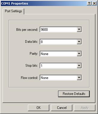
Figure 4-4 Setting communications parameters
Step 6: Click <OK>. The HyperTerminal dialogue box appears.
Figure 4-5 HyperTerminal window
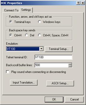
Step 7: Select File/Properties.
Step 8: In the Properties dialog box, select the Settings tab, as shown in Figure 4-6.
Step 9: Select VT100 or Auto detect in the Emulation dropdown menu.
Step 10: Click <OK>.
4.4 Booting the Switch
4.4.1 Verifying Installation before Power-up
Before powering up the switch, check that:
l
Both the power cord and the
grounding wire are correctly connected.
l
Proper power supply is used.
l The console cable is correctly connected.
l The console terminal (or PC) has been started and the related parameters have been set on it.
4.4.2 Powering up the Switch
For the models in the S3610 series, the displayed Boot ROM information is similar. Following is the Boot ROM information displayed on the S3610-52P:
Starting......
*************************************************************
* *
* H3C S3610-52P BOOTROM, Version 129 *
* *
*************************************************************
Copyright (c) 2004-2007 Hangzhou H3C Tech. Co., Ltd.
Creation date: Apr 5 2007, 15:47:28
CPU Clock Speed : 200MHz
BUS Clock Speed : 33MHz
Memory Size : 128MB
Board checking.......................................LSA1LTSG
SDRAM fast selftest.......................................OK!
Flash fast selftest.......................................OK!
CPLD selftest.............................................OK!
Switch chip selftest......................................OK!
Slot 1/1/1 has no module or get slot type error
Slot 1/1/2 has no module or get slot type error
Slot 1/1/3 has no module or get slot type error
Slot 1/1/4 has no module or get slot type error
PHY selftest..............................................OK!
Please check port leds..............................finished!
The switch Mac is: 000F-E200-2200
Press Ctrl-B to enter Boot Menu... 5
To enter the Boot Menu, press <Ctrl+B> within five seconds after the message “Press Ctrl-B to enter Boot Menu... 5” appears. Otherwise, when the waiting time changes from 5 to 0, the system automatically boots up and displays:
**************************************************************************
* Copyright (c) 2004-2007 Hangzhou H3C Tech. Co., Ltd. All rights reserved.* * Without the owner's prior written consent, *
* no decompiling or reverse-engineering shall be allowed. *
**************************************************************************
User interface aux0 is available.
Press ENTER to get started.
The appearance of “Please press ENTER” indicates that the switch has completed its automatic boot.
Press <Enter>; the system displays:
<H3C>
You can configure the switch now.
& Note:
A wide range of command views are available for H3C Series Switches. For more information on configuration commands and command line interfaces, refer to H3C S3610&S5510 Series Ethernet Switches Operation Manual and H3C S3610&S5510 Series Ethernet Switches Command Manual.
Chapter 5 Loading Boot ROM and Host Software
Switch software loading through serial ports in the past is time consuming and cannot be operated remotely. To address these problems, TFTP and FTP are used to allow software and file downloading through Ethernet ports. The following subsections describe how to load software and files in these two approaches.
5.1 Introduction to Loading Approaches
To load software remotely, use FTP or TFTP.
To load software at the local, use XMODEM at the console port or TFTP/FTP at an Ethernet port.
& Note:
Ensure that the Boot ROM and host software versions that you download can work with each other.
5.2 Loading Software Locally
If your terminal is directly connected to the switch, you can load Boot ROM and host software locally. But before that, make sure they are correctly connected.
& Note:
The steps that you should take to load Boot ROM program and host software are the same, except that during Boot ROM program loading you need to press <Ctrl +U> after accessing the Boot ROM menu and will view different prompt information. Boot ROM loading procedures are described below for example.
5.2.1 Boot Menu
Starting......
*************************************************************
* *
* H3C S3610-52P BOOTROM, Version 129 *
* *
*************************************************************
Copyright (c) 2004-2007 Hangzhou H3C Tech. Co., Ltd.
Creation date: Apr 5 2007, 15:47:28
CPU Clock Speed : 200MHz
BUS Clock Speed : 33MHz
Memory Size : 128MB
Board checking.......................................LSA1LTSG
SDRAM fast selftest.......................................OK!
Flash fast selftest.......................................OK!
CPLD selftest.............................................OK!
Switch chip selftest......................................OK!
Slot 1/1/1 has no module or get slot type error
Slot 1/1/2 has no module or get slot type error
Slot 1/1/3 has no module or get slot type error
Slot 1/1/4 has no module or get slot type error
PHY selftest..............................................OK!
Please check port leds..............................finished!
The switch Mac is: 000F-E200-2200
Press Ctrl-B to enter Boot Menu... 5
Press <Ctrl+B> as prompted. The system displays:
Password :
Input the correct Boot ROM password (no password is set by default). The system enters the following Boot Menu:
BOOT MENU
1. Download application file to flash
2. Select application file to boot
3. Display all files in flash
4. Delete file from flash
5. Modify bootrom password
6. Enter bootrom upgrade menu
7. Skip current configuration file
8. Set bootrom password recovery
9. Set switch startup mode
0. Reboot
Enter your choice(0-9):
5.2.2 Loading Software from Console Port Using XMODEM
I. Introduction to XMODEM
XMODEM is a file transfer protocol widely used for its simplicity and good performance. XMODEM transfers files through the console port, supporting data packets of 128 bytes and 1 KB. With respect to reliability, it supports checksum, CRC, and the error packet retransmission mechanism. Normally, the maximum number of retransmission attempts is ten.
XMODEM transfer is completed by receiving and sending programs together. Receiving program initiates packet checking method negotiation by sending the negotiation character. If negotiation passes, the sending program starts packet transfer. Upon receipt of a complete packet, the receiving program checks it using the agreed-upon check method. If the check succeeds, the receiving program sends an acknowledgement character; if the check fails, it sends a reject character. Upon receipt of the acknowledgement, the sending program continues to send the next packet; upon receipt of the reject, it retransmits the packet.
II. Loading Boot ROM
Follow these steps to download the Boot ROM program:
Step 1: Enter <6> or <Ctrl + U> in the Boot Menu to access the Boot ROM loading menu shown below:
Bootrom
update menu:
1.
Set TFTP protocol parameter
2.
Set FTP protocol parameter
3.
Set XMODEM protocol parameter
0. Return to boot menu
Enter your choice(0-3):
Step 2: Enter <3> in the loading menu to download through XMODEM. The system displays the following download speed setting menu:
Please select your download baudrate:
1.* 9600
2. 19200
3. 38400
4. 57600
5. 115200
0. Return
Enter your choice (0-5):
Step 3: Choose an appropriate download baud rate. Enter <5> for example to download at 115200 bps. The system displays the following information:
Download baudrate is 115200 bps
Please change the terminal's baudrate to 115200 bps and select XMODEM protocol
Press enter key when ready
& Note:
You do not need to modify the HyperTerminal’s baud rate if you have chosen 9600 bps, and thus can skip Steps 4 through 6 and proceed to Step 7 directly. At this time, the system does not display the above information.
Step 4: Enter HyperTerminal’s [File/Properties] menu, click <Configuration> in the popup dialog box, select the baud rate of 115200 bps in the Console Port Configuration dialog box.
Figure 5-1 Properties dialog box
Figure 5-2 Console Port Configuration dialog box
Step 5: Click <Disconnect> to disconnect the HyperTerminal from the switch and then click <Call> to re-establish the connection, thus validating the baud rate setting.
Figure 5-3 <Disconnect> and <Call> buttons
& Note:
After changing terminal’s baud rate, you must disconnect and connect the terminal emulation program to validate the new configuration.
Step 6: Press <Enter> to start program loading. The system displays the following information:
Now please start transfer file with XMODEM protocol.
If you want to exit, Press <Ctrl+X>.
Loading ...CCCCCCCCCC
Step 7: Select [Transfer/Send File] in the HyperTerminal’s window, and in the popup dialog box similar to the following figure click <Browse>, select the software you need to download, and set the protocol to XMODEM.
Figure 5-4 Send File dialog box
Step 8: Click <Send>. The system displays the following interface.
Figure 5-5 Sending File interface
Step 9: After completing loading, the system displays the following information:
Loading ...CCCCCCCCCC done!
& Note:
You do not need to reset the HyperTerminal’s baud rate and can skip the last step if you have chosen 9600 bps. In this case, the system does not display the above prompt message but “BootROM is updating now.....................................done!” instead.
Step 10: Reset HyperTerminal’s baud rate to 9600 bps with reference to Steps 5 and 6 described above. Then, press any key as prompted. The system will display the following information when it completes the loading.
Bootrom updating.....................................done!
III. Loading host software
Follow these steps to download host software of the switch:
Step 1: Select <1> in the Boot Menu. The system displays the following information:
1.
Set TFTP protocol parameter
2.
Set FTP protocol parameter
3.
Set XMODEM protocol parameter
0. Return to boot menu
Enter your choice(0-3):3
Select <3>. The subsequent steps are the same as those for loading Boot ROM, except for the program to be downloaded in prompt messages.
5.2.3 Loading Software from an Ethernet Port Using TFTP
I. Introduction to TFTP
Trivial File Transfer Protocol is a TCP/IP protocol used for file transfer between clients and servers. It uses UDP to provide unreliable data stream transfer service.
II. Loading Boot ROM
Step 1: Select an Ethernet port on the switch for loading and connect it to the PC where the file to be downloaded is stored. (You must know PC’s IP address). Besides, connect the console port on the switch to an external PC. This PC can be the same one that stores the file to be downloaded.
Step 2: Run the TFTP Server program on the PC connected to the Ethernet port, and specify the path for program loading.
![]() Caution:
Caution:
TFTP Server program is not provided with the H3C Series Switches.
Step 3: Run terminal emulation program on the PC that is connected to the console port. Start the switch, access the Boot Menu, and then enter the download protocol menu.
To download the Boot ROM program, enter <6> or <Ctrl + U> to access the menu for Boot ROM downloading when the system displays: “Enter your choice(0-9):”
Bootrom
update menu:
1.
Set TFTP protocol parameter
2.
Set FTP protocol parameter
3.
Set XMODEM protocol parameter
0. Return to boot menu
Enter your choice(0-3):
Step 4: In the download protocol menu, press <1> to select TFTP protocol to download Boot ROM or host software. Press <Enter>. The system displays the following information:
Load File name
Switch IP address ¬(This address and the server IP address must be on the same network segment)
Server IP address ¬ (IP address of the PC where the file is stored)
Step 5: Input the TFTP parameter values and press <Enter>. The system displays the following information:
Are you sure to update your bootrom?Yes or No(Y/N)
Step 6: Press <Y> to start file downloading and <N> to return to the program downloading menu. Suppose you press <Y> and then <Enter>. The system starts Boot ROM program downloading and automatically starts Boot ROM loading. After finishing loading, it displays the following information:
Loading........................................done
Bootrom updating..........done!
III. Loading host software
Follow these steps to download host software of the switch.
Step 1: Select <1> in the Boot Menu. The system displays the following information:
1.
Set TFTP protocol parameter
2.
Set FTP protocol parameter
3.
Set XMODEM protocol parameter
0. Return to boot menu
Enter your choice(0-3):3
Select <1>. The subsequent steps are the same as those for loading Boot ROM, except for the program to be downloaded in prompt messages.
5.2.4 Loading Software from an Ethernet Port Using FTP
I. Introduction to FTP
With an Ethernet port, you can also use the switch as the FTP server or client to download or configuration files. The following subsections describe how to load software by using the switch as the FTP client for example.
II. Loading Boot ROM
& Note:
When loading the Boot ROM, the switch can act as the FTP client only.
Step 1: Select an Ethernet port on the switch for loading and connect it to the PC where the file to be downloaded is stored. (You must know PC’s IP address). Besides, connect the console port on the switch to an external PC. This PC can be the same one that stores the file to be downloaded.
Step 2: Run the FTP Server program on the PC that is connected to the Ethernet port, and specify the path for program loading.
Step 3: Run terminal emulation program on the PC connected to the console port. Start the switch, access the Boot Menu, and then enter the download protocol menu.
To download the Boot ROM program, enter <6> or <Ctrl + U> to access the menu for Boot ROM downloading when the system displays: “Enter your choice(0-9):”
Bootrom
update menu:
1.
Set TFTP protocol parameter
2.
Set FTP protocol parameter
3.
Set XMODEM protocol parameter
0. Return to boot menu
Enter your choice(0-3):
Step 4: In the download protocol menu, press <2> to select FTP protocol to download Boot ROM and host software. Press <Enter>. The system displays the following information:
Load File name
Switch IP address ¬(This address and the server IP address must be on the same network segment)
Server IP address ¬(IP address of the PC that stores the file)
FTP User Name
FTP User Password
Step 5: Input the FTP parameter values and press <Enter>. The system displays:
Are you sure to update your bootrom?Yes or No(Y/N)
Step 6: Press <Y> to start file downloading and <N> to return to the program downloading menu. Suppose you press <Y> and then <Enter>. The system starts program downloading and upon its completion, starts writing to Flash. After completing the writing operation, the system displays:
Loading........................................done
Bootrom updating..........done!
III. Loading host software
Follow these steps to download host software:
Step 1: Select <1> in the Boot Menu. The system displays:
1. Set TFTP protocol parameter
2.
Set FTP protocol parameter
3.
Set XMODEM protocol parameter
0. Return to boot menu
Enter your choice(0-3):3
Select <2>. The subsequent steps are the same as those for loading Boot ROM, except for the program to be downloaded in prompt messages.
5.3 Loading Software Remotely
If your terminal is connected to the switch by a network, you can load Boot ROM and host software remotely.
5.3.1 Loading Software Remotely Using FTP
Run FTP server on a local PC, provided you have configured username and password and have set the correct file directory. Suppose IP address of the PC is 10.10.110.1. Telnet to the switch and FTP the host program to the switch.
Provided that the host program is SWITCH.app and the Boot ROM program is SWITCH.btm, you can take these steps after telnet ting to the switch.
Step 1: FTP the software to the switch.
<H3C> ftp 10.10.110.1
Trying ...
Press CTRL+K to abort
Connected.
220 WFTPD 2.0 service (by Texas Imperial Software) ready for new user
User(none):lyt
331 Give me your password, please
Password:
230 Logged in successfully
[ftp] get SWITCH.app SWITCH.app
[ftp] get SWITCH.btm SWITCH.btm
[ftp] bye
Step 2: Load Boot ROM.
<H3C> bootrom update file SWITCH.btm
This command will update bootrom file, Continue? [Y/N]y
Now updating bootrom, please wait...
BootRom file updating finished!
Step 3: Load the host software.
<H3C> boot-loader file SWITCH.bin
This command will set boot file, Continue? [Y/N]:y
The specified file will be used as a boot file at the next time!
<H3C> display boot-loader
The current boot app is: s3610_s5510-cmw520-r0001p02.bin
The app that will boot upon reboot is: SWITCH.bin
<H3C> reboot
& Note:
The configurations that you just make cannot survive a reboot. Make sure you have saved them before you have the system reboot.
To validate the downloaded Boot ROM and host software, you must reboot the switch. In case of inadequate Flash memory space, you can delete some of the program files in Flash, those that are no longer in use for example, after completing Boot ROM loading. Then FTP the host program to the switch.
& Note:
Power disconnection must be prevented during the loading process.
5.3.2 Loading Software Remotely Using TFTP
TFTP is similar to FTP in remote software downloading. But with TFTP, the switch can only be used as the client to download software to its Flash memory from the TFTP server. After that, the remaining steps are the same as remote loading using FTP.
Chapter 6 Maintenance and Troubleshooting
6.1 Dealing with Loading Failures
If software loading fails, the system operates with the original version.
To address the failure cause, take these steps:
Check that the physical ports are correctly and securely connected. If they are not, reconnect them correctly and restart loading.
Check information about the loading procedures for input errors on the HyperTerminal.
l If XMODEM is used, check that you have reset the baud rate of the HyperTerminal to 9600 bps after loading the software with another baud rate.
l If TFTP is used, check that you have correctly specified the TFTP parameters: server and switch IP addresses; name of the software to be loaded; and path for the TFTP server to operate on program files.
l If FTP is used, check that you have correctly specified the FTP parameters: server and switch IP addresses; name of the software to be loaded; and username and password.
Contact your sales agent for help if you cannot address the problem after taking the preceding two steps.
6.2 Dealing with Password Loss
6.2.1 Dealing with User Password Loss
If you lost your user password, enter the Boot Menu first:
BOOT MENU
1. Download application file to flash
2. Select application file to boot
3. Display all files in flash
4. Delete file from flash
5. Modify bootrom password
6. Enter bootrom upgrade menu
7. Skip current configuration file
8. Set bootrom password recovery
9. Set switch startup mode
0. Reboot
Enter your choice(0-9):
Select <7> and have the switch reboot. The user password is deleted at the reboot to allow you access the switch without password.
6.2.2 Recovering the Boot ROM Password
Contact your sales agent for help.
6.3 Dealing with Power System Failures
You can know whether the power system has failed by reading the PWR LED on the front panel. If the power system is operating normally, the PWR LED is ON. If not, check that:
l The switch power cord is correctly connected.
l The power source can work with the switch.
6.4 Dealing with Configuration System Failures
If the switch is operating normally after it is powered up, it displays the start-up information on the console terminal. If the configuration system has failed, it displays illegible characters or nothing at all.
I. No information on the terminal
Take these steps to address the problem:
Check that:
l
The power system is operating
normally.
l
The console cable is connected
correctly.
Check that the console cable is in good condition and the terminal (HyperTerminal for example) parameter settings are correct.
II. Illegible characters on the terminal
Make sure you have set on your terminal (HyperTerminal):
Baud rate = 9600
Data bits = 8
Parity check = none
Stop bits = 1
Flow control = none
Terminal emulation = VT100
Reconfigure the parameters if their values are different.
Chapter 7 Optional Interface Modules
![]() Caution:
Caution:
l Invisible rays may emit from the optical interface if the interface is not installed with an optical connector or not covered by a dustproof cover, so you are strongly recommended not to stare at the optical interface.
l If the optical interface is not installed with an optical connector, it must be covered with a dustproof cover.
l Before connecting the optical fiber, please confirm that the optical connector matches with the optical fiber.
7.1 8-Port 100Base-FX Single Mode/Multi-Mode
Module
8-port 100Base-FX
multi-mode module provides 8 100Base-FX multi-mode optical interfaces.
8-port 100Base-FX
single mode module provides 8 100Base-FX single mode optical interfaces.
8-port 100Base-FX multi-mode module and 8-port 100Base-FX single mode module are similar in appearance. The former is introduced as example:
7.1.1 Module Panel and LEDs
The panel of 8-port 100Base-FX single mode module is shown as follows:
Figure 7-1 Panel of 8-port 100Base-FX single mode module
The meaning of panel LEDs is described in the following table:
Table 7-1 Meaning of LEDs on 8-port 100Base-FX single mode/multi-mode module panel
|
LED |
State |
|
LINK |
OFF means that the line is disconnected. ON means the line is connected. |
|
ACTIVE |
OFF means that no data is being transceived. Blinking means data is being transceived. |
7.1.2 Module Interface Optical Fiber
Interface attributes of 8-port 100Base-FX multi-mode/single mode module under the working condition of 100Base-FX full-duplex.
8-port 100Base-FX multi-mode/single mode module works in 100 Mbps full-duplex mode. The following table lists its interface attributes.
Table 7-2 Interface attributes of 8-port 100Base-FX
multi-mode/single mode module
|
Description |
||
|
8-port 100Base-FX single mode module |
8-port 100Base-FX multi-mode module |
|
|
Interface connector |
LC |
|
|
Number of connectors |
8 |
|
|
Interface attribute |
100 Mbps full-duplex |
|
|
Medium and maximum transmission distance |
9/125 µm single mode optical fiber 15 km (9.3 mi) |
62.15/125
µm multi-mode optical fiber 2 km |
7.2 8-Port 10Base-T/100Base-TX Module
7.2.1 Module Panel and LEDs
The following figure shows the panel of 8-port 10Base-T/100Base-TX module:
Figure 7-2 Panel of 8-port 10Base-T/100Base-TX module
The description of the panel LEDs is given in the following table:
Table 7-3 Meaning of LEDs on 10Base-T/100Base-TX module panel
|
LED |
State |
|
LINK |
OFF means that the line is disconnected. ON means the line is connected. |
|
ACTIVE |
OFF means that no data is being transceived. Blinking means data is being transceived. |
7.2.2 Module Interface Cable
8-port 10Base-T/100Base-TX module interface employs an RJ-45 connector with a Category 5 cables. The module supports MDI/MDI-X auto-sensing, and can work in the modes of auto-negotiation, full-duplex and half-duplex. The description of the interface attributes is given in the following table:
Table 7-4 Interface attributes of 8-port 10Base-T/100Base-TX module
|
Attribute |
Description |
|
Interface connector |
RJ-45 |
|
Number of connectors |
8 |
|
Interface attribute |
10/100 Mbps half-duplex 10/100 Mbps full-duplex MDI/MDI-X
auto-sensing |
|
Medium and maximum transmission distance |
Category-5 twisted pair with a maximum transmission distance of 100 m (328 ft) |
7.3 8-Port 100 Mbps SFP Module Port Attributes
8-port 100 Mbps SFP module provides you eight SFP module interfaces. The hot-swappable feature and flexible selection method of SFP module enhance the flexibility of user networking.
7.3.1 Module Panel and LEDs
The following figure shows the panel of 8-port 100 Mbps SFP module:
Figure 7-3 Panel of 8-port 100 Mbps SFP module
The description of the panel LEDs is given in the following table:
Table 7-5 Meaning of LEDs on 8-port 100 Mbps SFP module panel
|
State |
|
|
LINK |
OFF means that the line is disconnected. ON means the line is connected. |
|
ACTIVE |
OFF means that no data is being transceived. Blinking means data is being transceived. |
7.3.2 Module Interface Cable
8-port 100 Mbps SFP module interface operates in 100 Mbps full-duplex mode. The description of the interface attributes is given in the following table:
Table 7-6 Interface attributes of 8-port 100 Mbps SFP module
|
SFP Module |
Connector of optical interface |
Optical fiber specification |
Maximum transmission distance |
|
SFP-FE-SX-MM1310-A |
LC |
50/125 µm
multi-mode optical fiber |
2 km (about 1.2 mi) |
|
SFP-FE-LX-SM1310-A |
9/125 µm single mode optical fiber |
15 km (9 mi) |
|
|
SFP-FE-LH40-SM1310 |
9/125 µm single mode optical fiber |
40 km (25 mi) |
|
|
SFP-FE-LH80-SM1550 |
9/125 µm single mode optical fiber |
80 km (50 mi) |
