- 产品与解决方案
- 行业解决方案
- 服务
- 支持
- 合作伙伴
- 关于我们


17-GRE和OSPF结合使用典型配置举例
本章节下载: 17-GRE和OSPF结合使用典型配置举例 (183.78 KB)
H3C S6860产品 GRE和OSPF结合使用典型配置举例
Copyright © 2018 新华三技术有限公司 版权所有,保留一切权利。
非经本公司书面许可,任何单位和个人不得擅自摘抄、复制本文档内容的部分或全部,并不得以任何形式传播。
除新华三技术有限公司的商标外,本手册中出现的其它公司的商标、产品标识及商品名称,由各自权利人拥有。
本文档中的信息可能变动,恕不另行通知。
目 录
本文档介绍了GRE隧道和OSPF相结合使用的典型配置举例。
本文档中的配置均是在实验室环境下进行的配置和验证,配置前设备的所有参数均采用出厂时的缺省配置。如果您已经对设备进行了配置,为了保证配置效果,请确认现有配置和以下举例中的配置不冲突。
本文假设您已了解GRE隧道和OSPF的相关特性。
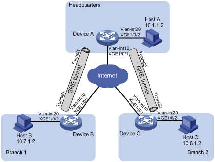
如图1所示,Device A为某机构总部网关,Device B和Device C为分支网关,运营商为各网关分配了公网IP地址,并保证网关之间可以通信,要求:
· 总部和分支之间建立GRE隧道,通过隧道使各总部、分支机构可以实现互访;
· 配置OSPF协议使网关上存在通过Tunnel接口到达目的地址的路由表项。
图1 GRE和OSPF结合使用典型配置举例组网图
|
设备 |
接口 |
IP地址 |
设备 |
接口 |
IP地址 |
|
Device A |
Vlan-int10 |
191.2.1.1/24 |
Device B |
Vlan-int10 |
191.3.1.1/24 |
|
|
Vlan-int20 |
10.1.1.1/24 |
|
Vlan-int20 |
10.7.1.1/24 |
|
|
Tunnel 1 |
10.5.1.1/24 |
|
Tunnel 1 |
10.5.1.2/24 |
|
|
Tunnel 2 |
10.6.1.1/24 |
|
|
|
|
Device C |
Vlan-int10 |
191.4.1.1/24 |
|
|
|
|
|
Vlan-int20 |
10.8.1.1/24 |
|
|
|
|
|
Tunnel 2 |
10.6.1.2/24 |
|
|
|
本举例是在S6860-CMW710-R2612版本上进行配置和验证的。
封装后的报文不能根据目的地址和路由表进行第二次三层转发,需要将封装后的报文发送给业务环回组,由业务环回组将报文回送给转发模块后,再进行三层转发。因此,需要创建tunnel类型的业务环回组,以实现隧道报文的接收和发送。
配置网关设备之间的IPv4路由协议,确保设备之间IPv4报文能够正常交互,具体配置过程略。
# 配置接口VLAN-interface 10的IP地址。
<DeviceA> system-view
[DeviceA] vlan 10
[DeviceA-vlan10] port Ten-GigabitEthernet 1/0/1
[DeviceA-vlan10] quit
[DeviceA] interface vlan-interface 10
[DeviceA-vlan-interface10] ip address 191.2.1.1 255.255.255.0
[DeviceA-vlan-interface10] quit
# 请参考以上方法配置上图中Device A其它接口的IP地址,配置步骤这里省略。
# 创建业务环回组1,并配置服务类型为tunnel。
[DeviceA] service-loopback group 1 type tunnel
# 将接口Ten-GigabitEthernet 1/0/3加入业务环回组1。
[DeviceA] interface Ten-GigabitEthernet 1/0/3
[DeviceA-Ten-GigabitEthernet1/0/3] port service-loopback group 1
[DeviceA-Ten-GigabitEthernet1/0/3] quit
# 创建Tunnel1接口,并指定隧道模式为GRE over IPv4隧道。
[DeviceA] interface tunnel 1 mode gre
# 配置Tunnel1接口的IP地址。
[DeviceA-Tunnel1] ip address 10.5.1.1 24
# 配置Tunnel1接口的源接口为VLAN-interface 10。
[DeviceA-Tunnel1] source vlan-interface 10
# 配置Tunnel1接口的目的端地址。
[DeviceA-Tunnel1] destination 191.3.1.1
[DeviceA-Tunnel1] quit
# 创建Tunnel2接口,并指定隧道模式为GRE over IPv4隧道。
[DeviceA] interface tunnel 2 mode gre
# 配置Tunnel2接口的IP地址。
[DeviceA-Tunnel2] ip address 10.6.1.1 24
# 配置Tunnel2接口的源接口为VLAN-interface 10。
[DeviceA-Tunnel2] source vlan-interface 10
# 配置Tunnel2接口的目的端地址。
[DeviceA-Tunnel2] destination 191.4.1.1
[DeviceA-Tunnel2] quit
# 启动OSPF,并配置其Router ID为10.6.1.1。
[DeviceA] router-id 10.6.1.1
[DeviceA] ospf 1
[DeviceA-ospf-1] area 0
[DeviceA-ospf-1-area-0.0.0.0] network 10.1.1.0 0.0.0.255
[DeviceA-ospf-1-area-0.0.0.0] network 10.5.1.0 0.0.0.255
[DeviceA-ospf-1-area-0.0.0.0] network 10.6.1.0 0.0.0.255
# 配置接口VLAN-interface10的IP地址。
<DeviceB> system-view
[DeviceB] vlan 10
[DeviceB-vlan10] port Ten-GigabitEthernet 1/0/1
[DeviceB-vlan10] quit
[DeviceB] interface vlan-interface 10
[DeviceB-vlan-interface10] ip address 191.3.1.1 255.255.255.0
[DeviceB-vlan-interface10] quit
# 请参考以上方法配置上图中Device B其它接口的IP地址,配置步骤这里省略。
# 创建业务环回组1,并配置服务类型为tunnel。
[DeviceB] service-loopback group 1 type tunnel
# 将接口Ten-GigabitEthernet1/0/3加入业务环回组1。
[DeviceB] interface Ten-GigabitEthernet 1/0/3
[DeviceB-Ten-GigabitEthernet1/0/3] port service-loopback group 1
[DeviceB-Ten-GigabitEthernet1/0/3] quit
# 创建Tunnel1接口,并指定隧道模式为GRE over IPv4隧道。
[DeviceB] interface tunnel 1 mode gre
# 配置Tunnel1接口的IP地址。
[DeviceB-Tunnel1] ip address 10.5.1.2 24
# 配置Tunnel1接口的源接口为VLAN-interface10。
[DeviceB-Tunnel1] source Vlan-interface 10
# 配置Tunnel1接口的目的端地址。
[DeviceB-Tunnel1] destination 191.2.1.1
[DeviceB-Tunnel1] quit
# 启动OSPF,并配置其Router ID为10.7.1.1。
[DeviceB] router-id 10.7.1.1
[DeviceB] ospf 1
[DeviceB-ospf-1] area 0
[DeviceB-ospf-1-area-0.0.0.0] network 10.7.1.0 0.0.0.255
[DeviceB-ospf-1-area-0.0.0.0] network 10.5.1.0 0.0.0.255
# 配置接口VLAN-interface10的IP地址。
<DeviceC> system-view
[DeviceC] vlan 10
[DeviceC-vlan10] port Ten-GigabitEthernet 1/0/1
[DeviceC-vlan10] quit
[DeviceC] interface Vlan-interface 10
[DeviceC-Vlan-interface10] ip address 191.4.1.1 255.255.255.0
[DeviceC-Vlan-interface10] quit
# 请参考以上方法配置上图中Device C其它接口的IP地址,配置步骤这里省略。
# 创建业务环回组1,并配置服务类型为tunnel。
[DeviceC] service-loopback group 1 type tunnel
# 将接口Ten-GigabitEthernet1/0/3加入业务环回组1。
[DeviceC] interface Ten-GigabitEthernet 1/0/3
[DeviceC-Ten-GigabitEthernet1/0/3] port service-loopback group 1
[DeviceC-Ten-GigabitEthernet1/0/3] quit
# 创建Tunnel2接口,并指定隧道模式为GRE over IPv4隧道。
[DeviceC] interface tunnel 2 mode gre
# 配置Tunnel2接口的IP地址。
[DeviceC-Tunnel2] ip address 10.6.1.2 24
# 配置Tunnel1接口的源接口为VLAN-interface10。
[DeviceC-Tunnel2] source Vlan-interface 10
# 配置Tunnel2接口的目的端地址。
[DeviceC-Tunnel2] destination 191.2.1.1
[DeviceC-Tunnel2] quit
# 启动OSPF,并配置其Router ID为10.8.1.1。
[DeviceC] router-id 10.8.1.1
[DeviceC] ospf 1
[DeviceC-ospf-1] area 0
[DeviceC-ospf-1-area-0.0.0.0] network 10.8.1.0 0.0.0.255
[DeviceC-ospf-1-area-0.0.0.0] network 10.6.1.0 0.0.0.255
(1) 从Host A可以ping通Host B。
C:\> ping 10.7.1.2
Pinging 10.7.1.2 with 32 bytes of data:
Reply from 10.7.1.2: bytes=32 time=19ms TTL=253
Reply from 10.7.1.2: bytes=32 time<1ms TTL=253
Reply from 10.7.1.2: bytes=32 time<1ms TTL=253
Reply from 10.7.1.2: bytes=32 time<1ms TTL=253
Ping statistics for 10.7.1.2:
Packets: Sent = 4, Received = 4, Lost = 0 (0% loss),
Approximate round trip times in milli-seconds:
Minimum = 0ms, Maximum = 19ms, Average = 4ms
(2) 从Host A可以ping通Host C。
C:\> ping 10.8.1.2
Pinging 10.8.1.2 with 32 bytes of data:
Reply from 10.8.1.2: bytes=32 time=18ms TTL=253
Reply from 10.8.1.2: bytes=32 time<1ms TTL=253
Reply from 10.8.1.2: bytes=32 time<1ms TTL=253
Reply from 10.8.1.2: bytes=32 time<1ms TTL=253
Ping statistics for 10.8.1.2:
Packets: Sent = 4, Received = 4, Lost = 0 (0% loss),
Approximate round trip times in milli-seconds:
Minimum = 0ms, Maximum = 19ms, Average = 4ms
(3) 从Host B可以ping通Host C。
C:\> ping 10.8.1.2
Pinging 10.8.1.2 with 32 bytes of data:
Reply from 10.8.1.2: bytes=32 time=20ms TTL=251
Reply from 10.8.1.2: bytes=32 time<1ms TTL=251
Reply from 10.8.1.2: bytes=32 time<1ms TTL=251
Reply from 10.8.1.2: bytes=32 time<1ms TTL=251
Ping statistics for 10.8.1.2:
Packets: Sent = 4, Received = 4, Lost = 0 (0% loss),
Approximate round trip times in milli-seconds:
Minimum = 0ms, Maximum = 19ms, Average = 4ms
· Device A
#
service-loopback group 1 type tunnel
#
vlan 10
#
vlan 20
#
interface Vlan-interface10
ip address 191.2.1.1 255.255.255.0
#
interface Vlan-interface20
ip address 10.1.1.1 255.255.255.0
#
interface Ten-GigabitEthernet1/0/1
port link-mode bridge
port access vlan 10
#
interface Ten-GigabitEthernet1/0/2
port link-mode bridge
port access vlan 20
#
interface Ten-GigabitEthernet1/0/3
port link-mode bridge
port service-loopback group 1
#
interface Tunnel1 mode gre
source vlan-interface10
destination 191.3.1.1
ip address 10.5.1.1 255.255.255.0
#
interface Tunnel2 mode gre
source vlan-interface10
destination 191.4.1.1
ip address 10.6.1.1 255.255.255.0
#
ospf 1
area 0.0.0.0
network 10.1.1.0 0.0.0.255
network 10.5.1.0 0.0.0.255
network 10.6.1.0 0.0.0.255
#
· Device B
#
service-loopback group 1 type tunnel
#
vlan 10
#
vlan 20
#
interface Vlan-interface10
ip address 191.3.1.1 255.255.255.0
#
interface Vlan-interface20
ip address 10.7.1.1 255.255.255.0
#
interface Ten-GigabitEthernet1/0/1
port link-mode bridge
port access vlan 10
#
interface Ten-GigabitEthernet1/0/2
port link-mode bridge
port access vlan 20
#
interface Ten-GigabitEthernet1/0/3
port link-mode bridge
port service-loopback group 1
#
interface Tunnel1 mode gre
source Vlan-interface10
destination 191.2.1.1
ip address 10.5.1.2 255.255.255.0
#
ospf 1
area 0.0.0.0
network 10.7.1.0 0.0.0.255
network 10.5.1.0 0.0.0.255
#
· Device C
#
service-loopback group 1 type tunnel
#
vlan 10
#
vlan 20
#
interface Vlan-interface10
ip address 191.4.1.1 255.255.255.0
#
interface Vlan-interface20
ip address 10.8.1.1 255.255.255.0
#
interface Ten-GigabitEthernet1/0/1
port link-mode bridge
port access vlan 10
#
interface Ten-GigabitEthernet1/0/2
port link-mode bridge
port access vlan 20
#
interface Ten-GigabitEthernet1/0/3
port link-mode bridge
port service-loopback group 1
#
interface Tunnel2 mode gre
source Vlan-interface10
destination 191.2.1.1
ip address 10.6.1.2 255.255.255.0
#
ospf 1
area 0.0.0.0
network 10.8.1.0 0.0.0.255
network 10.6.1.0 0.0.0.255
#
· H3C S6860系列以太网交换机 三层技术-IP业务配置指导-Release 26xx系列
· H3C S6860系列以太网交换机 三层技术-IP业务命令参考-Release 26xx系列
· H3C S6860系列以太网交换机 三层技术-IP路由配置指导-Release 26xx系列
· H3C S6860系列以太网交换机 三层技术-IP路由命令参考-Release 26xx系列
不同款型规格的资料略有差异, 详细信息请向具体销售和400咨询。H3C保留在没有任何通知或提示的情况下对资料内容进行修改的权利!


