- 产品与解决方案
- 行业解决方案
- 服务
- 支持
- 合作伙伴
- 关于我们


07-VLAN典型配置举例
本章节下载: 07-VLAN典型配置举例 (344.73 KB)
目 录
本章介绍了基于端口的VLAN和动态MAC VLAN典型配置举例。
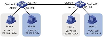
如图1所示:
· 为了避免广播报文泛滥和通信的安全性,某公司网络中使用VLAN技术来隔离部门间的二层流量。其中部门A使用VLAN 100,部门B使用VLAN 200。
· 部门A的终端用户使用192.168.1.0/24 IP网段,各终端用户配置的网关地址为192.168.1.1;部门B的终端用户使用192.168.2.0/24 IP网段,各终端用户配置的网关地址为192.168.2.1;
现要求通过配置基于端口的VLAN和VLAN接口实现下面应用需求:
· 同一VLAN内的主机能够二层互通,不同VLAN内的主机不能二层互通,能够三层互通。
· 通过配置使Device A作为部门A中用户的网关,Device B作为部门B中用户的网关。
# 创建VLAN 100,并将GigabitEthernet 1/0/1加入VLAN 100。
<DeviceA> system-view
[DeviceA] vlan 100
[DeviceA-vlan100] port gigabitethernet 1/0/1
[DeviceA-vlan100] quit
# 创建Vlan-interface 100,并配置其IP地址为192.168.1.1/24。
[DeviceA] interface Vlan-interface 100
[DeviceA-Vlan-interface100] ip address 192.168.1.1 24
[DeviceA-Vlan-interface100] quit
# 创建VLAN 200,并将GigabitEthernet 1/0/2加入VLAN 200。
[DeviceA] vlan 200
[DeviceA-vlan200] port gigabitethernet 1/0/2
[DeviceA-vlan200] quit
# 创建Vlan-interface 200,并配置其IP地址为192.168.2.2/24。
[DeviceA] interface Vlan-interface 200
[DeviceA-Vlan-interface200] ip address 192.168.2.2 24
[DeviceA-Vlan-interface200] quit
# 为了使Device A上VLAN 100和VLAN 200的报文能发送给Device B,将GigabitEthernet 1/0/3的链路类型配置为Trunk,并允许VLAN 100和VLAN 200的报文通过,取消允许VLAN 1通过。
[DeviceA] interface gigabitethernet 1/0/3
[DeviceA-GigabitEthernet1/0/3] port link-type trunk
[DeviceA-GigabitEthernet1/0/3] port trunk permit vlan 100 200
[DeviceA-GigabitEthernet1/0/3] undo port trunk permit vlan 1
[DeviceA-GigabitEthernet1/0/3] quit
(2) 配置Device B
# 创建VLAN 100,并将GigabitEthernet 1/0/1加入VLAN 100。
<DeviceB> system-view
[DeviceB] vlan 100
[DeviceB-vlan100] port gigabitethernet 1/0/1
[DeviceB-vlan100] quit
# 创建Vlan-interface 100,并配置其IP地址为192.168.1.2/24。
[DeviceB] interface Vlan-interface 100
[DeviceB-Vlan-interface100] ip address 192.168.1.2 24
[DeviceB-Vlan-interface100] quit
# 创建VLAN 200,并将GigabitEthernet 1/0/2加入VLAN 200。
[DeviceB] vlan 200
[DeviceB-vlan200] port gigabitethernet 1/0/2
[DeviceB-vlan200] quit
# 创建Vlan-interface 200,并配置其IP地址为192.168.2.1/24。
[DeviceB] interface Vlan-interface 200
[DeviceB-Vlan-interface200] ip address 192.168.2.1 24
[DeviceB-Vlan-interface200] quit
# 为了使Device A上VLAN 100和VLAN 200的报文能发送给Device B,将GigabitEthernet 1/0/3的链路类型配置为Trunk,并允许VLAN 100和VLAN 200的报文通过,取消允许VLAN 1通过。
[DeviceB] interface gigabitethernet 1/0/3
[DeviceB-GigabitEthernet1/0/3] port link-type trunk
[DeviceB-GigabitEthernet1/0/3] port trunk permit vlan 100 200
[DeviceB-GigabitEthernet1/0/3] undo port trunk permit vlan 1
[DeviceB-GigabitEthernet1/0/3] quit
(1) 通过display vlan命令查看显示信息验证配置是否成功,以查看Device A上VLAN 100和VLAN 200的配置信息为例。
[DeviceA] display vlan 100
VLAN ID: 100
VLAN Type: static
Route Interface: configured
IP Address: 192.168.1.1
Subnet Mask: 255.255.255.0
Description: VLAN 0100
Name: VLAN 0100
Tagged Ports:
GigabitEthernet1/0/3
Untagged Ports:
GigabitEthernet1/0/1
[DeviceA] display vlan 200
VLAN ID: 200
VLAN Type: static
Route Interface: configured
IP Address: 192.168.2.2
Subnet Mask: 255.255.255.0
Description: VLAN 0200
Name: VLAN 0200
Tagged Ports:
GigabitEthernet1/0/3
Untagged Ports:
GigabitEthernet1/0/2
(2) Host A和Host C能够互相ping通。查看Host A的ARP表,表中有Host C的IP地址和MAC地址对应的ARP表项。查看Host C的ARP表,表中有Host A的IP地址和MAC地址对应的ARP表项。
(3) Host A和Host D能够互相ping通。查看Host A的ARP表,表中没有Host D的ARP表项。查看Host D的ARP表,表中也没有Host A的ARP表项。
#
vlan 100
#
vlan 200
#
interface Vlan-interface100
ip address 192.168.1.1 255.255.255.0
#
interface Vlan-interface200
ip address 192.168.2.2 255.255.255.0
#
interface GigabitEthernet1/0/1
port link-mode bridge
port access vlan 100
#
interface GigabitEthernet1/0/2
port link-mode bridge
port access vlan 200
#
interface GigabitEthernet1/0/3
port link-mode bridge
port link-type trunk
undo port trunk permit vlan 1
port trunk permit vlan 100 200
#
· Device B
#
vlan 100
#
vlan 200
#
interface Vlan-interface100
ip address 192.168.1.2 255.255.255.0
#
interface Vlan-interface200
ip address 192.168.2.1 255.255.255.0
#
interface GigabitEthernet1/0/1
port link-mode bridge
port access vlan 100
#
interface GigabitEthernet1/0/2
port link-mode bridge
port access vlan 200
#
interface GigabitEthernet1/0/3
port link-mode bridge
port link-type trunk
undo port trunk permit vlan 1
port trunk permit vlan 100 200
#
![]()
本例中使用的iMC版本为可以为iMC PLAT 5.2(E0401)、iMC EAD 5.2(E0401)或iMC UAM 5.2(E0401)。
如图2所示,某公司为了隔离广播报文以及实现通信安全,给不同的部门指定了不同的VLAN,销售部属于VLAN 2;技术支持部属于VLAN 3;研发部属于VLAN 4。
现要求通过配置动态MAC VLAN实现以下应用需求:
· 终端通过802.1X认证后接入网络;
· Meeting room为员工提供了临时办公场所,终端可以通过Device A的任意端口接入公司网络,但接入后只能划分到自己部门所在的VLAN。如图2所示,Host A、Host B、Host C分别归属于VLAN 2、VLAN 3、VLAN 4。
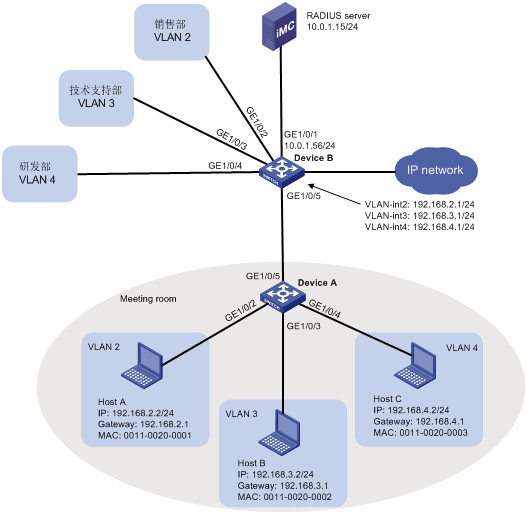
· 基于MAC的VLAN功能只能在Hybrid端口配置。
· 基于MAC的VLAN功能主要用于在用户的接入设备的下行端口上进行配置,因此不能和聚合功能同时使用。
# 创建RADIUS认证方案macvlan,指定认证和计费服务器的IP地址均为10.0.1.15,密钥均为expert(该参数需要和iMC服务器上的配置保持一致),认证时不需要携带域名。
<DeviceA> system-view
[DeviceA] radius scheme macvlan
New Radius scheme
[DeviceA-radius-macvlan] server-type extended
[DeviceA-radius-macvlan] primary authentication 10.0.1.15
[DeviceA-radius-macvlan] primary accounting 10.0.1.15
[DeviceA-radius-macvlan] key authentication expert
[DeviceA-radius-macvlan] key accounting expert
[DeviceA-radius-macvlan] user-name-format without-domain
[DeviceA-radius-macvlan] quit
# 配置域参数。因为所有用户上线都需要进行认证,所以直接使用缺省域system,在system下进行配置。
[DeviceA] domain system
[DeviceA-isp-system] authentication lan-access radius-scheme macvlan
[DeviceA-isp-system] authorization lan-access radius-scheme macvlan
[DeviceA-isp-system] accounting lan-access radius-scheme macvlan
[DeviceA-isp-system] quit
# 全局使能802.1X功能。
[DeviceA] undo port-security enable
[DeviceA] dot1x
802.1X is enabled globally.
# 使能接口GigabitEthernet1/0/2、GigabitEthernet1/0/3和GigabitEthernet1/0/4的802.1X功能。
[DeviceA] dot1x interface gigabitethernet 1/0/2 to gigabitethernet 1/0/4
802.1x is enabled on port GigabitEthernet1/0/2.
802.1x is enabled on port GigabitEthernet1/0/3.
802.1x is enabled on port GigabitEthernet1/0/4.
# 配置端口GigabitEthernet1/0/2、GigabitEthernet1/0/3和GigabitEthernet1/0/4的链路类型为Hybrid,并使能端口的MAC VLAN功能。
[DeviceA] interface gigabitethernet 1/0/2
[DeviceA-GigabitEthernet1/0/2] port link-type hybrid
[DeviceA-GigabitEthernet1/0/2] mac-vlan enable
[DeviceA-GigabitEthernet1/0/2] quit
[DeviceA] interface gigabitethernet 1/0/3
[DeviceA-GigabitEthernet1/0/3] port link-type hybrid
[DeviceA-GigabitEthernet1/0/3] mac-vlan enable
[DeviceA-GigabitEthernet1/0/3] quit
[DeviceA] interface gigabitethernet 1/0/4
[DeviceA-GigabitEthernet1/0/4] port link-type hybrid
[DeviceA-GigabitEthernet1/0/4] mac-vlan enable
[DeviceA-GigabitEthernet1/0/4] quit
# 将端口GigabitEthernet1/0/5的链路类型配置为Trunk,并允许VLAN 2、VLAN 3和VLAN 4通过。
[DeviceA] interface gigabitethernet 1/0/5
[DeviceA-GigabitEthernet1/0/5] port link-type trunk
[DeviceA-GigabitEthernet1/0/5] port trunk permit vlan 2 to 4
[DeviceA-GigabitEthernet1/0/5] quit
# GigabitEthernet1/0/1是一个三层接口用于认证服务器的接入,IP地址为10.0.1.56。
<DeviceB> system-view
[DeviceB] interface gigabitethernet 1/0/1
[DeviceB] port link-mode route
[DeviceB-GigabitEthernet1/0/1] ip address 10.0.1.56 24
[DeviceB-GigabitEthernet1/0/1] quit
# GigabitEthernet1/0/2用于销售部的接入,属于VLAN 2;GigabitEthernet1/0/3用于技术支持部的接入,属于VLAN 3;GigabitEthernet1/0/4用于研发部的接入,属于VLAN 4。
[DeviceB] vlan 2
[DeviceB-vlan2] port gigabitethernet 1/0/2
[DeviceB-vlan2] vlan 3
[DeviceB-vlan3] port gigabitethernet 1/0/3
[DeviceB-vlan3] vlan 4
[DeviceB-vlan4] port gigabitethernet 1/0/4
[DeviceB-vlan4] quit
# 创建VLAN 2接口、VLAN 3接口和VLAN 4接口,并分别配置IP地址(如图2所示),用于实现不同VLAN之间报文的三层互通。
[DeviceB] interface vlan-interface 2
[DeviceB-Vlan-interface2] ip address 192.168.2.1 24
[DeviceB-Vlan-interface2] interface vlan-interface 3
[DeviceB-Vlan-interface3] ip address 192.168.3.1 24
[DeviceB-Vlan-interface3] interface vlan-interface 4
[DeviceB-Vlan-interface4] ip address 192.168.4.1 24
[DeviceB-Vlan-interface4] quit
# 将端口GigabitEthernet1/0/5的端口类型配置为Trunk,允许VLAN 2、VLAN 3和VLAN 4通过。
[DeviceA] interface gigabitethernet 1/0/5
[DeviceA-GigabitEthernet1/0/5] port link-type trunk
[DeviceA-GigabitEthernet1/0/5] port trunk permit vlan 2 to 4
[DeviceA-GigabitEthernet1/0/5] quit
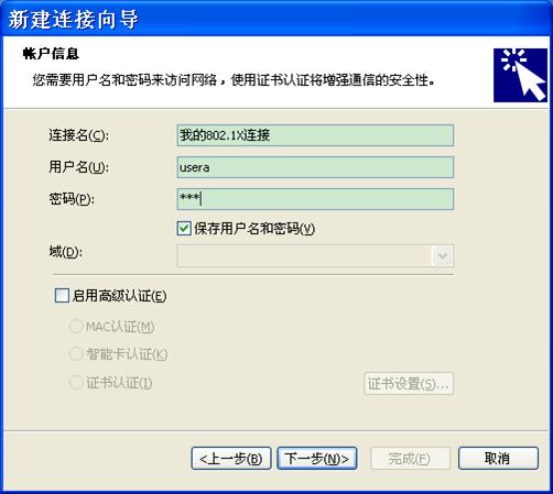
# 在PC机上安装H3C iNode智能管理客户端。
# 在iNode上创建一个新连接,选择接入认证协议类型为802.1X,选择连接类型为普通连接,用户名为usera,密码为aaa。
图3 新建连接向导
# 将PC的IP地址设定为192.168.2.2(也可以通过DHCP server动态分配,192.168.2.1/24网段即可),子网掩码设定为255.255.255.0,默认网关的IP地址为192.168.2.1/24。
# 在PC机上安装H3C iNode智能管理客户端。
# 在iNode上创建一个新连接,选择接入认证协议类型为802.1X,选择连接类型为普通连接,用户名为userb,密码为bbb。
# 将PC的IP地址设定为192.168.3.2(也可以通过DHCP server动态分配,192.168.3.1/24网段即可),子网掩码设定为255.255.255.0,默认网关的IP地址为192.168.3.1/24。
# 在PC机上安装H3C iNode智能管理客户端。
# 在iNode上创建一个新连接,选择接入认证协议类型为802.1X,选择连接类型为普通连接,用户名为userc,密码为ccc。
# 将PC的IP地址设定为192.168.4.2(也可以通过DHCP server动态分配,192.168.4.1/24网段即可),子网掩码设定为255.255.255.0,默认网关的IP地址为192.168.4.1/24。
· 选择“业务”页签。
· 在界面左侧的导航栏中选择“用户接入管理 > 接入设备管理 > 接入设备配置”。
· 单击<增加>按钮,进入“增加接入设备”页面。
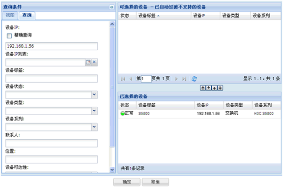
· 单击<选择>按钮,选择iMC平台中的设备。
· 使用查询功能快速定位设备,将符合条件的设备增加到“已选择的设备”区域。
· 选中设备,单击<确定>按钮。
图4 选取设备
· 配置共享密钥为expert,其它参数使用缺省值即可,单击<完成>按钮,接入设备增加成功。
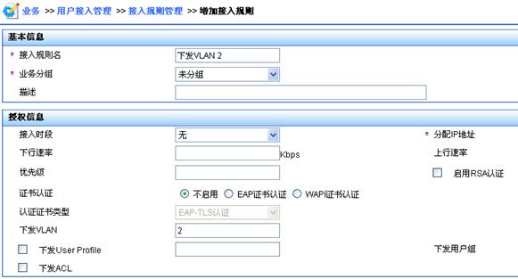
(2) 增加接入规则
· 选择“业务”页签。
· 在界面左侧的导航栏中选择“用户接入管理 > 接入规则管理”。
· 单击<增加>按钮。
· 配置接入规则名为“下发VLAN 2”,下发VLAN为VLAN 2,其它参数使用缺省值即可。
· 单击<确定>按钮,接入规则增加成功。
图5 增加接入规则
· 参照以上步骤增加接入规则“下发VLAN 3”,下发VLAN为VLAN 3;增加接入规则“下发VLAN 4”,下发VLAN为VLAN 4。
(3) 增加服务
· 选择“业务”页签。
· 在界面左侧的导航栏中选择“用户接入管理 > 服务配置管理”。
· 单击<增加>按钮。
· 配置服务名为serverA,缺省接入规则选择“下发VLAN 2”,其它参数使用缺省值即可,单击<确定>按钮,服务增加成功。
图6 增加服务配置
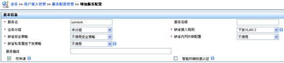
· 参照以上步骤增加服务增加服务serverB,缺省接入规则选择“下发VLAN 3”;增加服务serverC,缺省接入规则选择“下发VLAN 4”。
· 选择“用户”页签。
· 在界面左侧的导航栏中选择“用户管理 > 增加用户”。
· 增加一个全新的用户。用户姓名可以是用户的代号,方便iMC管理员识别不同用户;证件号码可以输入用户的电话号码,方便iMC管理员联系用户,如下图所示。
· 单击<确定>按钮,用户增加成功。
图7 增加用户

· 在界面左侧的导航栏中选择“接入用户视图 > 所有接入用户”,单击<增加>按钮,进入“增加接入用户”页面。
· 单击<选择>按钮,在弹出的用户列表中根据“用户姓名”或“证件号码”查询用户,选择符合条件的用户,单击<确定>按钮完成接入用户选择。
· 设置帐号名(即用户上网用帐号)为usera、密码(即用户上网用密码)为aaa,选择关联的服务serverA,其它参数使用缺省值,单击<确定>按钮,接入用户增加成功。
图8 增加接入用户
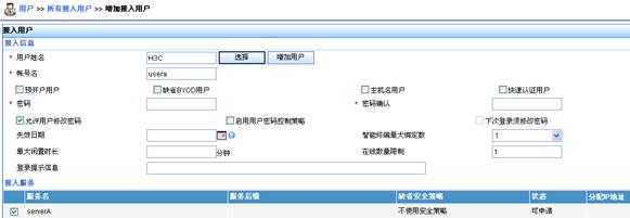
· 参照以上步骤增加帐号userb,密码为bbb,关联服务serverB;增加帐号userc,密码为ccc,关联服务serverC。
(1) 在Host A上使用802.1X连接,用户名usera,密码aaa,上线成功;在Host B上使用802.1X连接,用户名userb,密码bbb,上线成功;在Host C上使用802.1X连接,用户名userc,密码ccc,上线成功。
(2) 查看MAC VLAN列表,可以看出Host A和VLAN 2、Host B和VLAN 3、Host C和VLAN 4的表项已经动态生成。当GigabitEthernet1/0/2收到Host A的报文时,会给它添加VLAN 2的Tag;当GigabitEthernet1/0/3收到Host B的报文时,会给它添加VLAN 3的Tag;当GigabitEthernet1/0/4收到Host C的报文时,会给它添加VLAN 4的Tag。
[DeviceA] display mac-vlan all
The following MAC VLAN addresses exist:
S:Static D:Dynamic
MAC ADDR MASK VLAN ID PRIO STATE
--------------------------------------------------------
0011-0020-0001 ffff-ffff-ffff 2 0 D
0011-0020-0002 ffff-ffff-ffff 3 0 D
0011-0020-0003 ffff-ffff-ffff 4 0 D
· Device A
#
dot1x
#
radius scheme macvlan
server-type extended
primary authentication 10.0.1.15
primary accounting 10.0.1.15
key authentication expert
key accounting expert
user-name-format without-domain
#
domain system
authentication lan-access radius-scheme macvlan
authorization lan-access radius-scheme macvlan
accounting lan-access radius-scheme macvlan
#
interface GigabitEthernet1/0/2
port link-mode bridge
port link-type hybrid
port hybrid vlan 1 untagged
mac-vlan enable
dot1x
#
interface GigabitEthernet1/0/3
port link-mode bridge
port link-type hybrid
port hybrid vlan 1 untagged
mac-vlan enable
dot1x
#
interface GigabitEthernet1/0/4
port link-mode bridge
port link-type hybrid
port hybrid vlan 1 untagged
mac-vlan enable
dot1x
#
interface GigabitEthernet1/0/5
port link-mode bridge
port link-type trunk
port trunk permit vlan 1 to 4
· Device B
#
vlan 2 to 4
#
interface Vlan-interface2
ip address 192.168.2.1 255.255.255.0
#
interface Vlan-interface3
ip address 192.168.3.1 255.255.255.0
#
interface Vlan-interface4
ip address 192.168.4.1 255.255.255.0
#
interface GigabitEthernet1/0/1
port link-mode route
ip address 10.0.1.56 255.255.255.0
#
interface GigabitEthernet1/0/2
port link-mode bridge
port access vlan 2
#
interface GigabitEthernet1/0/3
port link-mode bridge
port access vlan 3
#
interface GigabitEthernet1/0/4
port link-mode bridge
port access vlan 4
#
interface GigabitEthernet1/0/5
port link-mode bridge
port link-type trunk
不同款型规格的资料略有差异, 详细信息请向具体销售和400咨询。H3C保留在没有任何通知或提示的情况下对资料内容进行修改的权利!


