- 产品与解决方案
- 行业解决方案
- 服务
- 支持
- 合作伙伴
- 关于我们


29-BFD典型配置举例
本章节下载: 29-BFD典型配置举例 (202.12 KB)
|
Copyright © 2018 新华三技术有限公司 版权所有,保留一切权利。 非经本公司书面许可,任何单位和个人不得擅自摘抄、复制本文档内容的部分或全部, 并不得以任何形式传播。本文档中的信息可能变动,恕不另行通知。 |
|
目 录
本文档介绍了BFD与路由协议联动的配置举例。
本文档中的配置均是在实验室环境下进行的配置和验证,配置前设备的所有参数均采用出厂时的缺省配置。如果您已经对设备进行了配置,为了保证配置效果,请确认现有配置和以下举例中的配置不冲突。
本文假设您已了解BFD特性和Track特性。
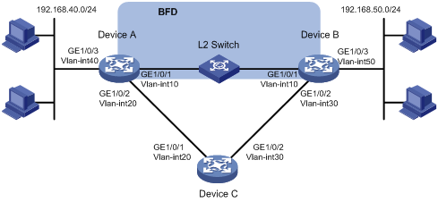
某公司内部网络如图1所示,从Device A到Device B有两条转发路径,下一跳分别为Device B和Device C。由于Device A和Device B之间物理距离较远,通过一个二层交换机L2 Switch作为中继。假设Device B不支持BFD,要求在Device A上使用静态路由与BFD联动技术,实现当Device B与二层交换机L2 Switch之间的链路出现故障(如链路down)时,Device A能快速感知,并将流量切换到Device C的链路上。
图1 静态路由与BFD联动配置组网图
|
设备 |
接口 |
IP地址 |
设备 |
接口 |
IP地址 |
|
Device A |
Vlan-int10 |
192.168.10.101/24 |
Device B |
Vlan-int10 |
192.168.10.102/24 |
|
|
Vlan-int20 |
192.168.20.101/24 |
|
Vlan-int30 |
192.168.30.101/24 |
|
|
Vlan-int40 |
192.168.40.101/24 |
|
Vlan-int50 |
192.168.50.101/24 |
|
Device C |
Vlan-int20 |
192.168.20.102/24 |
|
|
|
|
|
Vlan-int30 |
192.168.30.102/24 |
|
|
|
· 由于需要两端设备均支持BFD,才能够使用控制报文方式,本例中Device B不支持BFD,在Device A上配置的BFD功能仅能使用echo报文方式。
· echo报文方式下必须配置echo报文的源IP地址。IP地址可以任意指定,不需要与实际接口地址对应。建议不要将echo报文的源IP地址配置为属于该设备任何一个接口所在网段,避免对端发送大量的ICMP重定向报文造成网络拥塞。
本举例是在S5130EI_E-CMW710-R3106版本上进行配置和验证的。
(1) 配置Device A各接口的IP地址
<DeviceA> system-view
[DeviceA] vlan 10
[DeviceA-vlan10] port gigabitethernet 1/0/1
[DeviceA-vlan10] quit
[DeviceA] interface vlan-interface 10
[DeviceA-Vlan-interface10] ip address 192.168.10.101 24
[DeviceA-Vlan-interface10] quit
(2) 请参考以上方法配置图1中其它接口的IP地址,配置步骤这里省略
(1) 配置Device A
# 配置Device A到192.168.50.0/24网段的静态路由,Device A到Device B的流量优先走Device A –> L2 Switch–> Device B链路,当此链路发生故障时,流量切换到Device A –> Device C–> Device B链路上。
[DeviceA] ip route-static 192.168.50.0 24 vlan-interface 10 192.168.10.102 bfd echo-packet
[DeviceA] ip route-static 192.168.50.0 24 vlan-interface 20 192.168.20.102 preference 65
(2) 配置Device B
# 配置Device B到192.168.40.0/24网段的静态路由,Device B到Device A的流量优先走Device B –> L2 Switch–> Device A链路,当此链路发生故障时,流量切换到Device B –> Device C–> Device A链路上。
[DeviceB] ip route-static 192.168.40.0 24 vlan-interface 10 192.168.10.101
[DeviceB] ip route-static 192.168.40.0 24 vlan-interface 30 192.168.30.102 preference 65
(3) 配置Device C
# 配置Device C到192.168.40.0/24和192.168.50.0/24网段的静态路由。
[DeviceC] ip route-static 192.168.40.0 24 vlan-interface 20 192.168.20.101
[DeviceC] ip route-static 192.168.50.0 24 vlan-interface 30 192.168.30.101
# 静态路由支持的BFD会话方式为echo报文方式,该方式下必须配置BFD echo报文的源IP地址。IP地址可以任意指定,不需要与实际接口地址对应。建议不要将BFD echo报文的源IP地址配置为属于该设备任何一个接口所在网段。
[DeviceA] bfd echo-source-ip 10.10.10.10
# 配置接口接收BFD echo报文的最小时间间隔为100ms,单跳BFD检测时间倍数为3。
[DeviceA] interface vlan-interface 10
[DeviceA-Vlan-interface10] bfd min-echo-receive-interval 100
[DeviceA-Vlan-interface10] bfd detect-multiplier 3
[DeviceA-Vlan-interface10] quit
(1) Device A和Device B设备及之间的链路均正常工作时
# 在Device A查看静态路由信息。
[DeviceA] display ip routing-table protocol static
Summary Count : 2
Static Routing table Status : <Active>
Summary Count : 2
Destination/Mask Proto Pre Cost NextHop Interface
192.168.50.0/24 Static 60 0 192.168.10.102 Vlan10
192.168.50.0/24 Static 65 0 192.168.20.102 Vlan20
Static Routing table Status : <Inactive>
Summary Count : 0
以上显示信息表示Device A经过L2 Switch到达Device B。
# 查看BFD会话。
[DeviceA] display bfd session
Total Session Num: 1 Up Session Num: 1 Init Mode: Active
IPv4 Session Working Under Echo Mode:
LD/RD SourceAddr DestAddr State Holdtime Interface
67 192.168.10.101 192.168.10.102 Up 2000ms Vlan10
以上显示信息表示BFD会话已经创建。
(2) Device B与L2 Switch之间的链路出现故障时
# 查看静态路由。
[DeviceA] display ip routing-table protocol static
Summary Count : 1
Static Routing table Status : <Active>
Summary Count : 1
Destination/Mask Proto Pre Cost NextHop Interface
192.168.50.0/24 Static 65 0 192.168.20.102 Vlan20
Static Routing table Status : <Inactive>
Summary Count : 0
以上显示信息表示Device A经过Device C到达Device B。
· Device A:
#
bfd echo-source-ip 10.10.10.10
#
vlan 10
#
vlan 20
#
vlan 40
#
interface Vlan-interface10
ip address 192.168.10.101 255.255.255.0
bfd min-echo-receive-interval 100
bfd detect-multiplier 3
#
interface Vlan-interface20
ip address 192.168.20.101 255.255.255.0
#
interface Vlan-interface40
ip address 192.168.40.101 255.255.255.0
#
interface GigabitEthernet1/0/1
port access vlan 10
#
interface GigabitEthernet1/0/2
port access vlan 20
#
interface GigabitEthernet1/0/3
port access vlan 40
#
ip route-static 192.168.50.0 24 Vlan-interface10 192.168.10.102 bfd echo-packet
ip route-static 192.168.50.0 24 Vlan-interface20 192.168.20.102 preference 65
#
· Device B:
#
vlan 10
#
vlan 30
#
vlan 50
#
interface Vlan-interface10
ip address 192.168.10.102 255.255.255.0
#
interface Vlan-interface30
ip address 192.168.30.101 255.255.255.0
#
interface Vlan-interface50
ip address 192.168.50.101 255.255.255.0
#
interface GigabitEthernet1/0/1
port access vlan 10
#
interface GigabitEthernet1/0/2
port access vlan 30
#
interface GigabitEthernet1/0/3
port access vlan 50
#
ip route-static 192.168.40.0 24 Vlan-interface10 192.168.10.101
ip route-static 192.168.40.0 24 Vlan-interface30 192.168.30.102 preference 65
#
· Device C:
#
vlan 20
#
vlan 30
#
interface Vlan-interface30
ip address 192.168.20.102 255.255.255.0
#
interface Vlan-interface30
ip address 192.168.30.102 255.255.255.0
#
interface GigabitEthernet1/0/1
port access vlan 20
#
interface GigabitEthernet1/0/2
port access vlan 30
#
ip route-static 192.168.40.0 24 Vlan-interface20 192.168.20.101
ip route-static 192.168.50.0 24 Vlan-interface30 192.168.30.101
#
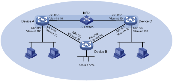
如图2所示,某公司通过一台二层交换机作为中继将两个相距较远的部门连接。Device A、Device B、Device C上运行RIP,建立RIP邻居关系,保证网络层相互可达。
公司希望在Device A上使用RIP与BFD联动技术,实现当Device C与二层交换机之间的链路出现故障(如链路down)时,BFD能够快速感知并通告RIP协议。
已知Device C不支持BFD功能,公司希望使用RIP与BFD联动技术,采用BFD echo报文方式实现当Device A或Device C与二层交换机之间的链路出现故障时,BFD能够快速感知并通告RIP协议。
现要求通过在Device A和Device C上配置RIP与BFD联动功能,实现:
· 监测通过L2 Switch通信的链路;
· 当链路出现故障时设备能够快速感知并通告RIP协议,快速切换到Device B链路进行通信。
图2 RIP与BFD联动配置组网图
|
设备 |
接口 |
IP地址 |
设备 |
接口 |
IP地址 |
|
Device A |
Vlan-int10 |
10.1.0.101/24 |
Device B |
Vlan-int20 |
192.168.0.102/24 |
|
|
Vlan-int20 |
192.168.0.101/24 |
|
Vlan-int30 |
13.1.1.101/24 |
|
|
Vlan-int100 |
120.1.1.1/24 |
|
|
|
|
Device C |
Vlan-int10 |
10.1.0.102/24 |
|
|
|
|
|
Vlan-int30 |
13.1.1.102/24 |
|
|
|
|
|
Vlan-int100 |
121.1.1.1/24 |
|
|
|
· 由于需要两端设备均支持BFD,才能够使用控制报文方式,本例中Device C不支持BFD,在Device A上配置的BFD功能仅能使用echo报文方式。
· echo报文方式下必须配置echo报文的源IP地址。IP地址可以任意指定,不需要与实际接口地址对应。建议不要将echo报文的源IP地址配置为属于该设备任何一个接口所在网段,避免对端发送大量的ICMP重定向报文造成网络拥塞。
本举例是在S5130EI_E-CMW710-R3106版本上进行配置和验证的。
(1) 配置Device A各接口的IP地址
<DeviceA> system-view
[DeviceA] vlan 10
[DeviceA-vlan10] port gigabitethernet 1/0/1
[DeviceA-vlan10] quit
[DeviceA] interface vlan-interface10
[DeviceA-Vlan-interface10] ip address 10.1.0.101 24
[DeviceA-Vlan-interface10] undo shutdown
[DeviceA-Vlan-interface10] quit
(2) 请参考以上方法配置图2中其它接口的IP地址,配置步骤这里省略
(1) 配置Device A
# 配置Device A的RIP基本功能,引入直连路由,并使能RIP的BFD功能。
<DeviceA> system-view
[DeviceA] rip 1
[DeviceA-rip-1] version 2
[DeviceA-rip-1] undo summary
[DeviceA-rip-1] network 10.1.0.0
[DeviceA-rip-1] network 192.168.0.0
[DeviceA-rip-1] import-route direct
[DeviceA-rip-1] quit
[DeviceA] interface vlan-interface 10
[DeviceA-Vlan-interface10] rip bfd enable
[DeviceA-Vlan-interface10] quit
(2) 配置Device B
# 配置Device B的RIP基本功能,引入直连路由。
<DeviceB> system-view
[DeviceB] rip 1
[DeviceB-rip-1] version 2
[DeviceB-rip-1] undo summary
[DeviceB-rip-1] network 192.168.0.0
[DeviceB-rip-1] network 13.1.1.0
[DeviceB-rip-1] import-route direct
[DeviceB-rip-1] quit
(3) 配置Device C
# 配置Device C的RIP基本功能,引入直连路由。
<DeviceC> system-view
[DeviceC] rip 1
[DeviceC-rip-1] version 2
[DeviceC-rip-1] undo summary
[DeviceC-rip-1] network 10.1.0.0
[DeviceC-rip-1] network 13.1.1.0
[DeviceC-rip-1] import-route direct
[DeviceC-rip-1] quit
# RIP支持的BFD会话方式为echo报文方式,该方式下必须配置BFD echo报文的源IP地址。IP地址可以任意指定,不需要与实际接口地址对应。建议不要将BFD echo报文的源IP地址配置为属于该设备任何一个接口所在网段。
[DeviceA] bfd echo-source-ip 11.11.11.11
# 配置接口接收BFD echo报文的最小时间间隔为100ms,单跳BFD检测时间倍数为3。
[DeviceA] interface vlan-interface 10
[DeviceA-Vlan-interface10] bfd min-echo-receive-interval 100
[DeviceA-Vlan-interface10] bfd detect-multiplier 3
[DeviceA-Vlan-interface10] quit
# 查看Device A上BFD会话信息,显示BFD会话已被创建,且状态为Up。
[DeviceA] display bfd session verbose
Total Session Num: 1 Up Session Num: 1 Init Mode: Active
IPv4 Session Working Under Echo Mode:
Local Discr: 2049
Source IP: 10.1.0.101 Destination IP: 10.1.0.102
Session State: Up Interface: Vlan-interface10
Hold Time: 1000ms Act Tx Inter: 100ms
Min Rx Inter: 100ms Detect Inter: 5000ms
Rx Count: 0 Tx Count: 910
Connect Type: Direct Running Up for: 00:00:46
Detect Mode: Async Slot: 0
Protocol: RIP
Diag Info: No Diagnostic
# 查看Device A上学到的路由121.1.1.0/24,可以看到Device A经过L2 Switch到达Device C。
<DeviceA> display ip routing-table 121.1.1.0 24 verbose
Summary Count : 1
Destination: 121.1.1.0/24
Protocol: RIP Process ID: 1
SubProtID: 0x1 Age: 04h20m37s
Cost: 1 Preference: 100
Tag: 0 State: Active Adv
OrigTblID: 0x0 OrigVrf: default-vrf
TableID: 0x2 OrigAs: 0
NBRID: 0x26000002 LastAs: 0
AttrID: 0xffffffff Neighbor: 10.1.0.102
Flags: 0x1008c OrigNextHop: 10.1.0.102
Label: NULL RealNextHop: 10.1.0.102
BkLabel: NULL BkNextHop: N/A
Tunnel ID: Invalid Interface: Vlan-interface10
BkTunnel ID: Invalid BkInterface: N/A
# 当Device C和二层交换机之间的链路发生故障,BFD快速检测到链路发生变化并立刻通告RIP。
%Oct 9 18:42:17:650 2013 Device A BFD/5/BFD_CHANGE_FSM: Sess[10.1.0.101/10.1.0.102, LD/RD:2049/2049, Interface:Vlan10, SessType:Echo, LinkType:INET] , Sta: UP-> DOWN, Diag:1
# 查看Device A上学到的路由121.1.1.0/24,可以看到Device A经过Device B到达Device C。
<DeviceA> display ip routing-table 121.1.1.0 24 verbose
Summary Count : 1
Destination: 121.1.1.0/24
Protocol: RIP Process ID: 2
SubProtID: 0x1 Age: 04h20m37s
Cost: 2 Preference: 100
Tag: 0 State: Active Adv
OrigTblID: 0x0 OrigVrf: default-vrf
TableID: 0x2 OrigAs: 0
NBRID: 0x26000002 LastAs: 0
AttrID: 0xffffffff Neighbor: 192.168.0.102
Flags: 0x1008c OrigNextHop: 192.168.0.102
Label: NULL RealNextHop: 192.168.0.102
BkLabel: NULL BkNextHop: N/A
Tunnel ID: Invalid Interface: Vlan-interface20
BkTunnel ID: Invalid BkInterface: N/A
· Device A:
#
bfd echo-source-ip 11.11.11.11
#
rip 1
undo summary
version 2
network 10.0.0.0
network 192.168.0.0
import-route direct
#
vlan 10
#
vlan 20
#
vlan 100
#
interface Vlan-interface10
ip address 10.1.0.101 255.255.255.0
bfd min-transmit-interval 100
bfd min-receive-interval 100
bfd detect-multiplier 3
#
interface Vlan-interface20
ip address 192.168.0.101 255.255.255.0
#
interface Vlan-interface100
ip address 120.1.1.1 255.255.255.0
#
interface GigabitEthernet1/0/1
port access vlan 10
#
interface GigabitEthernet1/0/2
port access vlan 20
#
interface GigabitEthernet1/0/3
port access vlan 100
#
· Device B:
#
rip 1
undo summary
version 2
network 192.168.0.0
network 13.1.1.0
import-route direct
#
vlan 20
#
vlan 30
#
interface Vlan-interface20
ip address 192.168.0.102 255.255.255.0
#
interface Vlan-interface30
ip address 13.1.1.101 255.255.255.0
#
interface GigabitEthernet1/0/1
port access vlan 20
#
interface GigabitEthernet1/0/2
port access vlan 30
#
· Device C:
#
rip 1
undo summary
version 2
network 10.1.0.0
network 13.1.1.0
import-route direct
#
vlan 10
#
vlan 30
#
vlan 100
#
interface Vlan-interface10
ip address 10.1.0.102 255.255.255.0
#
interface Vlan-interface30
ip address 13.1.1.102 255.255.255.0
#
interface Vlan-interface100
ip address 121.1.1.1 255.255.255.0
#
interface GigabitEthernet1/0/1
port access vlan 10
#
interface GigabitEthernet1/0/2
port access vlan 30
#
interface GigabitEthernet1/0/3
port access vlan 100
#
· H3C S5130-EI系列以太网交换机 可靠性配置指导-Release 3106
· H3C S5130-EI系列以太网交换机 可靠性命令参考-Release 3106
· H3C S5130-EI系列以太网交换机 二层技术-以太网交换配置指导-Release 3106
· H3C S5130-EI系列以太网交换机 二层技术-以太网交换命令参考-Release 3106
· H3C S5130-EI系列以太网交换机 三层技术-IP路由配置指导-Release 3106
· H3C S5130-EI系列以太网交换机 三层技术-IP路由命令参考-Release 3106
不同款型规格的资料略有差异, 详细信息请向具体销售和400咨询。H3C保留在没有任何通知或提示的情况下对资料内容进行修改的权利!


