- 产品与解决方案
- 行业解决方案
- 服务
- 支持
- 合作伙伴
- 关于我们


07-VLAN典型配置举例
本章节下载: 07-VLAN典型配置举例 (561.88 KB)
|
Copyright © 2018 新华三技术有限公司 版权所有,保留一切权利。 非经本公司书面许可,任何单位和个人不得擅自摘抄、复制本文档内容的部分或全部, 并不得以任何形式传播。本文档中的信息可能变动,恕不另行通知。 |
|
目 录
本文档介绍基于端口的VLAN、动态MAC VLAN、Super VLAN、Private VLAN的典型应用场景和配置举例。
本文档中的配置均是在实验室环境下进行的配置和验证,配置前设备的所有参数均采用出厂时的缺省配置。如果您已经对设备进行了配置,为了保证配置效果,请确认现有配置和以下举例中的配置不冲突。
本文档假设您已了解VLAN特性。
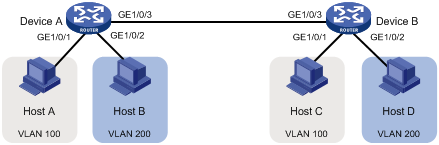
如图1所示,Host A和Host C属于部门A,但是通过不同的设备接入公司网络;Host B和Host D属于部门B,也通过不同的设备接入公司网络。为了通信的安全性,以及避免广播报文泛滥,公司网络中使用VLAN技术来隔离部门间的二层流量。其中部门A使用VLAN 100,部门B使用VLAN 200。
现要求同一VLAN内的主机能够互通,即Host A和Host C能够互通,Host B和Host D能够互通。
图1 基于端口的VLAN组网图
本举例是在S5130EI_E-CMW710-R3106版本上进行配置和验证的。
# 创建VLAN 100,并将GigabitEthernet1/0/1加入VLAN 100。
[DeviceA-vlan100] port gigabitethernet 1/0/1
[DeviceA-vlan100] quit
# 创建VLAN 200,并将GigabitEthernet1/0/2加入VLAN 200。
[DeviceA-vlan200] port gigabitethernet 1/0/2
[DeviceA-vlan200] quit
# 为了使Device A上VLAN 100和VLAN 200的报文能发送给Device B,将GigabitEthernet1/0/3的链路类型配置为Trunk,并允许VLAN 100和VLAN 200的报文通过。
[DeviceA] interface gigabitethernet 1/0/3
[DeviceA-GigabitEthernet1/0/3] port link-type trunk
[DeviceA-GigabitEthernet1/0/3] port trunk permit vlan 100 200
(2) Device B上的配置与Device A上的配置相同,不再赘述。
(3) 将Host A和Host C配置在一个网段,例如192.168.100.0/24;将Host B和Host D配置在一个网段,比如192.168.200.0/24。
(1) Host A和Host C能够互相ping通,但是均不能ping通Host B。Host B和Host D能够互相ping通,但是均不能ping通Host A。
# 查看Device A上VLAN 100和VLAN 200的配置信息,VLAN 100的报文仅允许通过接口GE1/0/3和GE1/0/1,VLAN 200的报文仅允许通过接口GE1/0/3和GE1/0/2。
[DeviceA-GigabitEthernet1/0/3] display vlan 100
VLAN ID: 100
VLAN type: Static
Route interface: Not configured
Description: VLAN 0100
Name: VLAN 0100
Tagged ports:
GigabitEthernet1/0/3
Untagged ports:
GigabitEthernet1/0/1
[DeviceA-GigabitEthernet1/0/3] display vlan 200
VLAN ID: 200
VLAN type: Static
Route interface: Not configured
Description: VLAN 0200
Name: VLAN 0200
Tagged ports:
GigabitEthernet1/0/3
Untagged ports:
GigabitEthernet1/0/2
Device B上的配置与Device A上的配置相同,此处仅以Device A的配置文件举例
#
vlan 100
#
vlan 200
#
interface GigabitEthernet1/0/1
port access vlan 100
#
interface GigabitEthernet1/0/2
port access vlan 200
#
interface GigabitEthernet1/0/3
port link-type trunk
port trunk permit vlan 1 100 200
#
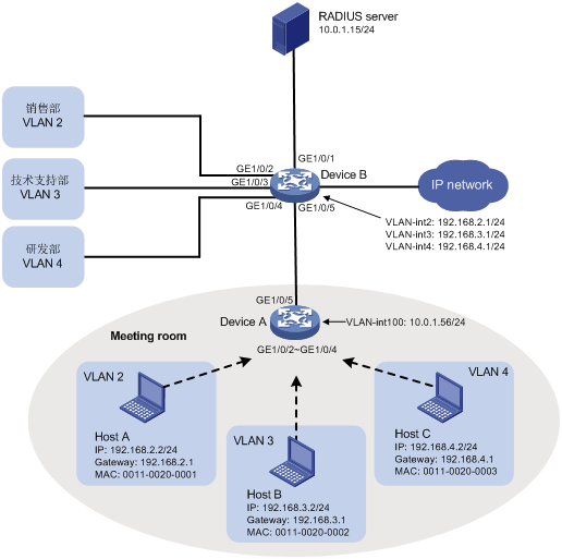
如图2所示,某公司为了隔离广播报文以及实现通信安全,给不同的部门指定了不同的VLAN。销售部属于VLAN 2,技术支持部属于VLAN 3,研发部属于VLAN 4。
现要求通过配置动态MAC VLAN功能实现以下应用需求:
· 终端用户通过802.1X认证后接入网络;
· Meeting room为员工提供了临时办公场所,终端用户可以通过Device A的任意端口接入公司网络,但接入后只能划分到自己部门所在的VLAN。
图2 动态MAC VLAN配置组网图
本举例是在S5130EI_E-CMW710-R3106版本上进行配置和验证的。
![]()
本例中使用的iMC版本为iMC PLAT 5.2(E0401)和iMC UAM 5.2(E0401) ,使用的iNode版本为iNode 5.2(E0406)。
· MAC VLAN功能只能在Hybrid端口上配置。
· MAC VLAN功能主要用于在用户的接入设备的下行端口上进行配置,因此不需要且不能和聚合功能同时使用。
· Super VLAN不能作为MAC VLAN表项中的VLAN。
# 创建RADIUS认证方案macvlan,指定认证和计费服务器的IP地址均为10.0.1.15,密钥均为expert(该参数需要和iMC服务器上的配置保持一致),认证时不需要携带域名。
<DeviceA> system-view
[DeviceA] radius scheme macvlan
New RADIUS scheme.
[DeviceA-radius-macvlan] primary authentication 10.0.1.15
[DeviceA-radius-macvlan] primary accounting 10.0.1.15
[DeviceA-radius-macvlan] key authentication simple expert
[DeviceA-radius-macvlan] key accounting simple expert
[DeviceA-radius-macvlan] user-name-format without-domain
[DeviceA-radius-macvlan] quit
# 在缺省域system下配置域参数。
[DeviceA] domain system
[DeviceA-isp-system] authentication lan-access radius-scheme macvlan
[DeviceA-isp-system] authorization lan-access radius-scheme macvlan
[DeviceA-isp-system] accounting lan-access radius-scheme macvlan
[DeviceA-isp-system] quit
# 批量使能接口GigabitEthernet1/0/2~GigabitEthernet1/0/4的802.1X功能。
[DeviceA] interface range gigabitethernet 1/0/2 to gigabitethernet 1/0/4
[DeviceA-if-range] dot1x
# 批量配置端口GigabitEthernet1/0/2~GigabitEthernet1/0/4的链路类型为Hybrid,并使能端口的MAC VLAN功能。
[DeviceA-if-range] port link-type hybrid
[DeviceA-if-range] mac-vlan enable
[DeviceA-if-range] quit
# 创建VLAN 100。
[DeviceA] vlan 100
[DeviceA-vlan100] quit
# 将端口GigabitEthernet1/0/5的链路类型配置为Trunk,并允许VLAN 2、VLAN 3、VLAN 4和VLAN 100通过。
[DeviceA] interface gigabitethernet 1/0/5
[DeviceA-GigabitEthernet1/0/5] port link-type trunk
[DeviceA-GigabitEthernet1/0/5] port trunk permit vlan 2 to 4 100
[DeviceA-GigabitEthernet1/0/5] quit
# 配置VLAN 100接口的IP地址为10.0.1.56,用于和认证服务器交互RADIUS报文。
[DeviceA] interface vlan-interface 100
[DeviceA-Vlan-interface100] ip address 10.0.1.56 24
[DeviceA-Vlan-interface100] quit
# 全局使能802.1X功能。
[DeviceA] dot1x
# 创建VLAN 2~VLAN 4。
<DeviceB> system-view
[DeviceB] vlan 2 to 4
# 创建VLAN 100。
[DeviceB] vlan 100
[DeviceB-vlan100] quit
# 将端口GigabitEthernet1/0/1加入VLAN 100。
[DeviceB] vlan 100
[DeviceB-vlan100] port gigabitethernet 1/0/1
[DeviceB-vlan100] quit
# GigabitEthernet1/0/2用于销售部的接入,加入VLAN 2;GigabitEthernet1/0/3用于技术支持部的接入,加入VLAN 3;GigabitEthernet1/0/4用于研发部的接入,加入VLAN 4。
[DeviceB] vlan 2
[DeviceB-vlan2] port gigabitethernet 1/0/2
[DeviceB-vlan2] vlan 3
[DeviceB-vlan3] port gigabitethernet 1/0/3
[DeviceB-vlan3] vlan 4
[DeviceB-vlan4] port gigabitethernet 1/0/4
[DeviceB-vlan4] quit
# 创建VLAN接口2~ 4,并分别配置图2中的IP地址,用于实现不同VLAN之间报文的三层互通。
[DeviceB] interface vlan-interface 2
[DeviceB-Vlan-interface2] ip address 192.168.2.1 24
[DeviceB-Vlan-interface2] interface vlan-interface 3
[DeviceB-Vlan-interface3] ip address 192.168.3.1 24
[DeviceB-Vlan-interface3] interface vlan-interface 4
[DeviceB-Vlan-interface4] ip address 192.168.4.1 24
[DeviceB-Vlan-interface4] quit
# 将端口GigabitEthernet1/0/5的端口类型配置为Trunk,允许VLAN 2~4和VLAN 100通过。
[DeviceB] interface gigabitethernet 1/0/5
[DeviceB-GigabitEthernet1/0/5] port link-type trunk
[DeviceB-GigabitEthernet1/0/5] port trunk permit vlan 2 to 4 100
[DeviceB-GigabitEthernet1/0/5] quit
· 选择“业务”页签。
· 在界面左侧的导航栏中选择“用户接入管理 > 接入设备管理 > 接入设备配置”。
· 单击<增加>按钮,进入“增加接入设备”页面。
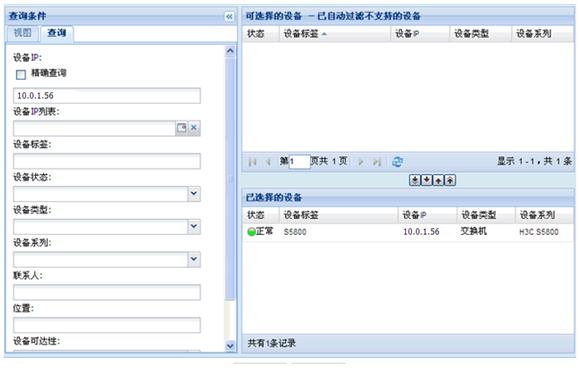
· 单击<选择>按钮,选择iMC平台中的设备。
· 在设备IP字段输入Device A上VLAN 100接口的IP地址10.0.1.56,使用查询功能快速定位接入设备Device A,将Device A增加到“已选择的设备”区域。
· 选中设备,单击<确定>按钮。
图3 选取设备
· 配置共享密钥为expert,其他参数使用缺省值即可,单击<完成>按钮,接入设备增加成功。
(2) 增加接入规则
· 选择“业务”页签。
· 在界面左侧的导航栏中选择“用户接入管理 > 接入规则管理”。
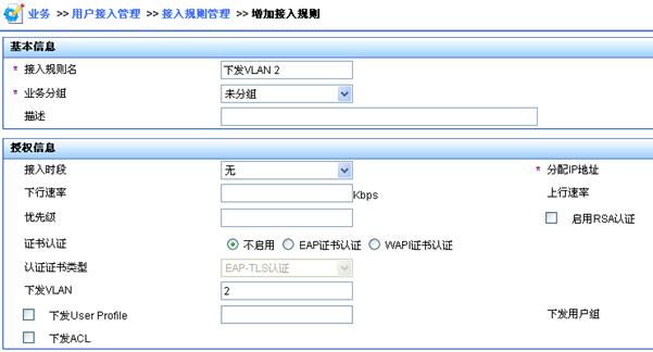
· 单击<增加>按钮。
· 配置接入规则名为“下发VLAN 2”,下发VLAN为VLAN 2,其他参数使用缺省值即可。
· 单击<确定>按钮,接入规则增加成功。
图4 增加接入规则
· 参照以上步骤增加接入规则“下发VLAN 3”,下发VLAN为VLAN 3;增加接入规则“下发VLAN 4”,下发VLAN为VLAN 4。
(3) 增加服务
· 选择“业务”页签。
· 在界面左侧的导航栏中选择“用户接入管理 > 服务配置管理”。
· 单击<增加>按钮。
· 配置服务名为serverA,缺省接入规则选择“下发VLAN 2”,其他参数使用缺省值即可,单击<确定>按钮,服务增加成功。
图5 增加服务配置
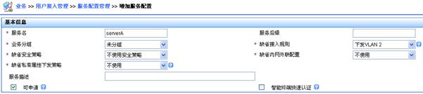
· 参照以上步骤增加服务增加服务serverB,缺省接入规则选择“下发VLAN 3”;增加服务serverC,缺省接入规则选择“下发VLAN 4”。
· 选择“用户”页签。
· 在界面左侧的导航栏中选择“用户管理 > 增加用户”。
· 增加一个全新的用户。用户姓名和证件号码的组合必须唯一,方便iMC管理员识别不同用户;证件号码可以输入用户的电话号码,方便iMC管理员联系用户,如下图所示。
· 单击<确定>按钮,用户增加成功。
图6 增加用户

· 在界面左侧的导航栏中选择“接入用户视图 > 所有接入用户”,单击<增加>按钮,进入“增加接入用户”页面。
· 单击<选择>按钮,在弹出的用户列表中根据“用户姓名”或“证件号码”查询用户,选择符合条件的用户,单击<确定>按钮完成接入用户选择。
· 设置帐号名(即用户上网用帐号)为usera、密码(即用户上网用密码)为aaa,选择关联的服务serverA,其他参数使用缺省值,单击<确定>按钮,接入用户增加成功。
图7 增加接入用户
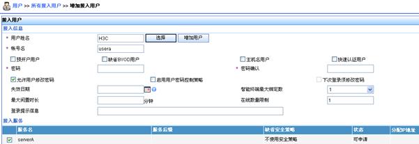
参照以上步骤增加帐号userb,密码为bbb,关联服务serverB;增加帐号userc,密码为ccc,关联服务serverC。
# 将PC的IP地址设定为192.168.2.2,子网掩码设定为255.255.255.0,默认网关的IP地址为192.168.2.1/24。
# 在PC机上安装H3C iNode智能管理客户端。
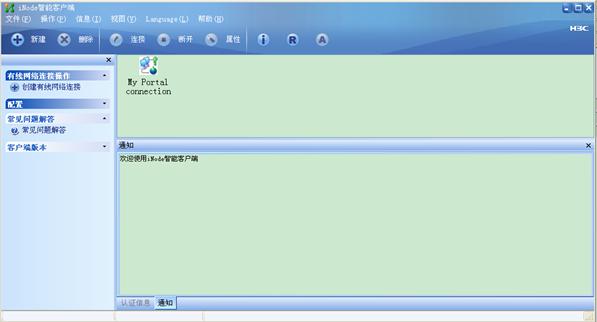
# 在iNode客户端界面上点击“新建”创建一个新连接。
图8 iNode客户端界面示意图
# 选择接入认证协议类型为802.1X。
图9 新建802.1X连接示意图

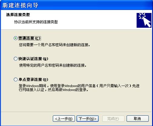
# 选择连接类型为普通连接。
图10 新建802.1X连接示意图
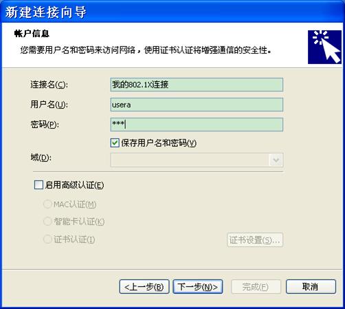
# 设置用户名为usera,密码为aaa。
图11 802.1X用户名、密码配置示意图
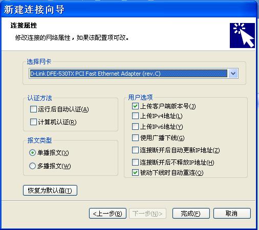
# 在连接属性页面选择待接入网络对应的网卡,其他参数选择默认值即可。
图12 802.1X连接属性配置示意图
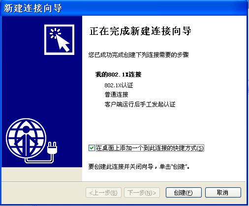
# 点击“创建”创建一个新连接。
图13 完成新建连接示意图
# 完成新建连接后,点击iNode客户端的<连接>按钮,发起802.1X连接。
# 将PC的IP地址设定为192.168.3.2,子网掩码设定为255.255.255.0,默认网关的IP地址为192.168.3.1/24。
# 在PC机上安装H3C iNode智能管理客户端。
# 在iNode上创建一个新连接,选择接入认证协议类型为802.1X,选择连接类型为普通连接,用户名为userb,密码为bbb。配置过程与配置Host A类似,具体步骤略。
# 将PC的IP地址设定为192.168.4.2,子网掩码设定为255.255.255.0,默认网关的IP地址为192.168.4.1/24。
# 在PC机上安装H3C iNode智能管理客户端。
# 在iNode上创建一个新连接,选择接入认证协议类型为802.1X,选择连接类型为普通连接,用户名为userc,密码为ccc。配置过程与配置Host A类似,具体步骤略。
(1) 在Host A上使用802.1X连接,用户名usera,密码aaa,上线成功;在Host B上使用802.1X连接,用户名userb,密码bbb,上线成功;在Host C上使用802.1X连接,用户名userc,密码ccc,上线成功。
(2) 查看MAC VLAN列表,可以看出Host A和VLAN 2、Host B和VLAN 3、Host C和VLAN 4的表项已经动态生成。当GigabitEthernet1/0/2收到Host A的报文时,会给它添加VLAN 2的Tag;当GigabitEthernet1/0/3收到Host B的报文时,会给它添加VLAN 3的Tag;当GigabitEthernet1/0/4收到Host C的报文时,会给它添加VLAN 4的Tag。
[DeviceA] display mac-vlan all
The following MAC VLAN entries exist:
State: S - Static, D – Dynamic
MAC address Mask VLAN ID Dot1q State
0011-0020-0001 ffff-ffff-ffff 2 0 D
0011-0020-0002 ffff-ffff-ffff 3 0 D
0011-0020-0003 ffff-ffff-ffff 4 0 D
· Device A
#
vlan 1
#
dot1x
#
interface Vlan-interface100
ip address 10.0.1.56 255.255.255.0
#
radius scheme macvlan
primary authentication 10.0.1.15
primary accounting 10.0.1.15
key authentication cipher $c$3$XwInB0VNLWc77yS07KunkmBbfdiFoou3sw==
key accounting cipher $c$3$mBUM9K5MWY4dOwH9NG+W2sVjbxiB9iEQcA==
user-name-format without-domain
#
domain system
authentication lan-access radius-scheme macvlan
authorization lan-access radius-scheme macvlan
accounting lan-access radius-scheme macvlan
#
interface GigabitEthernet1/0/2
port link-type hybrid
port hybrid vlan 1 untagged
mac-vlan enable
dot1x
#
interface GigabitEthernet1/0/3
port link-type hybrid
port hybrid vlan 1 untagged
mac-vlan enable
dot1x
#
interface GigabitEthernet1/0/4
port link-type hybrid
port hybrid vlan 1 untagged
mac-vlan enable
dot1x
#
interface GigabitEthernet1/0/5
port link-type trunk
port trunk permit vlan 1 to 4 100
· Device B
#
vlan 2 to 4
#
vlan 100
#
interface Vlan-interface2
ip address 192.168.2.1 255.255.255.0
#
interface Vlan-interface3
ip address 192.168.3.1 255.255.255.0
#
interface Vlan-interface4
ip address 192.168.4.1 255.255.255.0
#
interface GigabitEthernet1/0/1
port access vlan 100
#
interface GigabitEthernet1/0/2
port access vlan 2
#
interface GigabitEthernet1/0/3
port access vlan 3
#
interface GigabitEthernet1/0/4
port access vlan 4
#
interface GigabitEthernet1/0/5
port link-type trunk
port trunk permit vlan 1 to 4 100
#
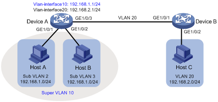
如图14所示:
· VLAN 2中的用户通过Device A的GigabitEthernet1/0/1接入网络,VLAN 3中的用户通过Device A的GigabitEthernet1/0/2接入网络。VLAN 2中有30个用户,VLAN 3中有50个用户。
· Device A的GigabitEthernet1/0/3和Device B的GigabitEthernet1/0/1属于VLAN 20。
· VLAN 20中的终端用户都使用192.168.2.0/24 网段的IP地址,使用192.168.2.1作为网关地址。
现要求通过配置Super VLAN功能实现以下应用需求:
· VLAN 2和VLAN 3中的终端用户都使用192.168.1.0/24网段的IP地址以节省IP地址资源,使用192.168.1.1作为网关地址。
· VLAN 2、VLAN 3、VLAN 20中的终端用户二层隔离,三层互通。
本举例是在S5130EI_E-CMW710-R3106版本上进行配置和验证的。
由于Super VLAN中不能包含物理端口,由此若某VLAN中已经包含物理端口,则该VLAN不能被配置为Super VLAN。
# 创建Super VLAN 10。
<DeviceA> system-view
[DeviceA] vlan 10
[DeviceA-vlan10] supervlan
[DeviceA-vlan10] quit
# 创建VLAN 2并将端口GigabitEthernet1/0/1加入VLAN 2。
[DeviceA] vlan 2
[DeviceA-vlan2] port gigabitethernet 1/0/1
[DeviceA-vlan2] quit
# 创建VLAN 3并将端口GigabitEthernet1/0/2加入VLAN 3。
[DeviceA] vlan 3
[DeviceA-vlan3] port gigabitethernet 1/0/2
[DeviceA-vlan3] quit
# 将Super VLAN 10和Sub VLAN 2和Sub VLAN 3关联。
[DeviceA] vlan 10
[DeviceA-vlan10] subvlan 2 3
[DeviceA-vlan10] quit
# 配置Super VLAN 10对应的VLAN接口的IP地址和本地代理ARP功能。
[DeviceA] interface vlan-interface 10
[DeviceA-Vlan-interface10] ip address 192.168.1.1 24
[DeviceA-Vlan-interface10] local-proxy-arp enable
[DeviceA-Vlan-interface10] quit
# 创建VLAN 20。
[DeviceA] vlan 20
[DeviceA-vlan20] quit
# 将端口GigabitEthernet1/0/3配置为Trunk端口并允许VLAN 20通过,取消允许VLAN 1通过。
[DeviceA] interface gigabitethernet 1/0/3
[DeviceA-GigabitEthernet1/0/3] port link-type trunk
[DeviceA-GigabitEthernet1/0/3] undo port trunk permit vlan 1
[DeviceA-GigabitEthernet1/0/3] port trunk permit vlan 20
# 配置VLAN 20对应的VLAN接口的IP地址。
[DeviceA] interface Vlan-interface 20
[DeviceA-Vlan-interface20] ip address 192.168.2.1 24
[DeviceA-Vlan-interface20] quit
# 创建VLAN 20。
[DeviceB] vlan 20
[DeviceB-vlan20] quit
# 将端口GigabitEthernet1/0/1配置为Trunk端口并允许VLAN 20通过,取消允许VLAN 1通过。
[DeviceB] interface gigabitethernet 1/0/1
[DeviceB-GigabitEthernet1/0/1] port link-type trunk
[DeviceB-GigabitEthernet1/0/1] undo port trunk permit vlan 1
[DeviceB-GigabitEthernet1/0/1] port trunk permit vlan 20
# 将端口GigabitEthernet1/0/2加入VLAN 20。
[DeviceB] vlan 20
[DeviceB-vlan20] port gigabitethernet 1/0/2
[DeviceB-vlan20] quit
(1) 查看Super VLAN配置信息。
[DeviceA] display supervlan
SuperVLAN ID : 10
SubVLAN ID : 2 3
VLAN ID: 10
VLAN Type: static
It is a Super VLAN.
Route Interface: configured
IP Address: 192.168.1.1
Subnet Mask: 255.255.255.0
Description: VLAN 0010
Name: VLAN 0010
Tagged Ports: none
Untagged Ports: none
VLAN ID: 2
VLAN Type: static
It is a Sub VLAN.
Route Interface: configured
IP Address: 192.168.1.1
Subnet Mask: 255.255.255.0
Description: VLAN 0002
Name: VLAN 0002
Tagged Ports: none
Untagged Ports:
GigabitEthernet1/0/1
VLAN ID: 3
VLAN Type: static
It is a Sub VLAN.
Route Interface: configured
IP Address: 192.168.1.1
Subnet Mask: 255.255.255.0
Description: VLAN 0003
Name: VLAN 0003
Tagged Ports: none
Untagged Ports:
GigabitEthernet1/0/2
(2) Host A和Host B可以互相ping通。查看Host A的ARP表,表中Host B的IP地址对应的MAC地址是Vlan-interface10的MAC地址。查看Host B的ARP表,表中Host A的IP地址对应的MAC地址也是Vlan-interface10的MAC地址。
(3) Host A和Host C可以互相ping通。查看Host A的ARP表,表中没有Host C的ARP表项。查看Host C的ARP表,表中也没有Host A的ARP表项。说明VLAN 2和VLAN 20二层隔离,三层互通。Host B和Host C互相ping的情况同理。
· Device A
#
vlan 2
#
vlan 3
#
vlan 10
supervlan
subvlan 2 3
#
vlan 20
#
interface Vlan-interface10
ip address 192.168.1.1 255.255.255.0
local-proxy-arp enable
#
interface Vlan-interface20
ip address 192.168.2.1 255.255.255.0
#
interface GigabitEthernet1/0/1
port access vlan 2
#
interface GigabitEthernet1/0/2
port access vlan 3
#
interface GigabitEthernet1/0/3
port link-type trunk
undo port trunk permit vlan 1
port trunk permit vlan 20
#
· Device B
#
vlan 20
#
interface GigabitEthernet1/0/1
port link-type trunk
undo port trunk permit vlan 1
port trunk permit vlan 20
#
interface GigabitEthernet1/0/2
port access vlan 20
#
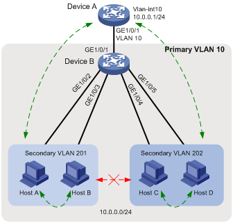
如图15所示:
· 汇聚层设备Device A为接入设备Device B分配了VLAN 10,网关接口VLAN-interface10可以和所有用户互通,以便用户可以通过Device A来访问外部网络。Device B连接的所有用户均处于同一网段10.0.0.0/24。
· Host A和B属于销售部,Host C和D属于财务部。为保证安全,需要使不同部门之间二层隔离,同部门的用户之间则可以互通。
现由于Device A不能为Device B分配更多VLAN,要求通过Private VLAN功能实现:
· Device A只需识别VLAN 10。
· Device B在Primary VLAN 10下为各部门配置不同的Secondary VLAN,使部门间二层隔离。
图15 Private VLAN典型配置举例组网图
Private VLAN功能只需要在接入设备Device B上配置。
本举例是在S5130EI_E-CMW710-R3106版本上进行配置和验证的。
系统缺省VLAN(VLAN 1)不支持Private VLAN相关配置。
# 配置VLAN 10为Primary VLAN。
<DeviceB> system-view
[DeviceB] vlan 10
[DeviceB-vlan10] private-vlan primary
[DeviceB-vlan10] quit
# 创建Secondary VLAN 201、202。
[DeviceB] vlan 201 to 202
# 建立Primary VLAN 10和Secondary VLAN 201、202的映射关系。
[DeviceB] vlan 10
[DeviceB-vlan10] private-vlan secondary 201 to 202
[DeviceB-vlan10] quit
# 配置上行端口GigabitEthernet1/0/1在VLAN 10中工作在promiscuous模式。
[DeviceB] interface gigabitethernet 1/0/1
[DeviceB-GigabitEthernet1/0/1] port private-vlan 10 promiscuous
[DeviceB-GigabitEthernet1/0/1] quit
# 将下行端口GigabitEthernet1/0/2、GigabitEthernet1/0/3添加到VLAN 201,GigabitEthernet1/0/4、GigabitEthernet1/0/5添加到VLAN 202,并配置它们工作在host模式。
[DeviceB] interface range gigabitethernet 1/0/2 to gigabitethernet 1/0/3
[DeviceB-if-range] port access vlan 201
[DeviceB-if-range] port private-vlan host
[DeviceB-if-range] quit
[DeviceB] interface range gigabitethernet 1/0/4 to gigabitethernet 1/0/5
[DeviceB-if-range] port access vlan 202
[DeviceB-if-range] port private-vlan host
[DeviceB-if-range] quit
# 创建VLAN 10。将接口GigabitEthernet1/0/1加入VLAN 10。
<DeviceA> system-view
[DeviceA] vlan 10
[DeviceA] quit
[DeviceA] interface gigabitethernet 1/0/1
[DeviceA-GigabitEthernet1/0/1] port access vlan 10
[DeviceA-GigabitEthernet1/0/1] quit
# 配置网关接口VLAN-interface10。
[DeviceA] interface vlan-interface 10
[DeviceA-Vlan-interface10] ip address 10.0.0.1 24
[DeviceA-Vlan-interface10] quit
# Device A可以ping通任意用户。查看ARP表,可以看到所有用户均属于VLAN 10。
[DeviceA] display arp
Type: S-Static D-Dynamic O-Openflow M-Multiport I-Invalid
IP address MAC address VLAN Interface Aging Type
10.0.0.2 d485-64a1-7e4a 10 GE1/0/1 19 D
10.0.0.3 7446-a0aa-7774 10 GE1/0/1 19 D
10.0.0.4 6805-ca05-39ae 10 GE1/0/1 20 D
10.0.0.5 6805-ca05-414e 10 GE1/0/1 20 D
# 显示Device B上的Private VLAN配置情况。
[DeviceB] display private-vlan
Primary VLAN ID: 10
Secondary VLAN ID: 201-202
VLAN ID: 10
VLAN type: Static
Private VLAN type: Primary
Route interface: Not configured
Description: VLAN 0010
Name: VLAN 0010
Tagged ports: None
Untagged ports:
GigabitEthernet1/0/1 GigabitEthernet1/0/2
GigabitEthernet1/0/3 GigabitEthernet1/0/4
GigabitEthernet1/0/5
VLAN ID: 201
VLAN type: Static
Private VLAN type: Secondary
Route interface: Not configured
Description: VLAN 0201
Name: VLAN 0201
Tagged ports: None
Untagged ports:
GigabitEthernet1/0/1 GigabitEthernet1/0/2
GigabitEthernet1/0/3
VLAN ID: 202
VLAN type: Static
Private VLAN type: Secondary
Route interface: Not configured
Description: VLAN 0202
Name: VLAN 0202
Tagged ports: None
Untagged ports:
GigabitEthernet1/0/1 GigabitEthernet1/0/4
GigabitEthernet1/0/5
可以看到,工作在promiscuous模式的端口GigabitEthernet1/0/1和工作在host模式的端口GigabitEthernet1/0/2~GigabitEthernet1/0/5均以Untagged方式允许VLAN报文通过。
# Host A、B之间可以互相ping通,Host C、D之间可以互相ping通。Host A、B与Host C、D之间均不能ping通。
· Device B
#
vlan 1
#
vlan 10
private-vlan primary
private-vlan secondary 201 to 202
#
vlan 201 to 202
#
interface GigabitEthernet1/0/1
port link-type hybrid
undo port hybrid vlan 1
port hybrid vlan 10 201 to 202 untagged
port hybrid pvid vlan 10
port private-vlan 10 promiscuous
#
interface GigabitEthernet1/0/2
port link-type hybrid
undo port hybrid vlan 1
port hybrid vlan 10 201 untagged
port hybrid pvid vlan 201
port private-vlan host
#
interface GigabitEthernet1/0/3
port link-type hybrid
undo port hybrid vlan 1
port hybrid vlan 10 201 untagged
port hybrid pvid vlan 201
port private-vlan host
#
interface GigabitEthernet1/0/4
port link-type hybrid
undo port hybrid vlan 1
port hybrid vlan 10 202 untagged
port hybrid pvid vlan 202
port private-vlan host
#
interface GigabitEthernet1/0/5
port link-type hybrid
undo port hybrid vlan 1
port hybrid vlan 10 202 untagged
port hybrid pvid vlan 202
port private-vlan host
#
· Device A
#
vlan 1
#
vlan 10
#
interface Vlan-interface10
ip address 10.0.0.1 255.255.255.0
#
interface GigabitEthernet1/0/1
port access vlan 10
#
· H3C S5130-EI系列以太网交换机 二层技术-以太网交换配置指导-Release 3106
· H3C S5130-EI系列以太网交换机 二层技术-以太网交换命令参考-Release 3106
· H3C S5130-EI系列以太网交换机 安全配置指导-Release 3106
· H3C S5130-EI系列以太网交换机 安全命令参考-Release 3106
不同款型规格的资料略有差异, 详细信息请向具体销售和400咨询。H3C保留在没有任何通知或提示的情况下对资料内容进行修改的权利!


