- Table of Contents
-
- H3C WX6103 Access Controller Switch Interface Board Configuration Guide-6W102
- 00-Preface
- 01-Login Configuration
- 02-VLAN Configuration
- 03-IP Addressing and IP Performance Configuration
- 04-QinQ-BPDU Tunneling Configuration
- 05-Port Correlation Configuration
- 06-Link Aggregation Configuration
- 07-MAC Address Table Management Configuration
- 08-Port Security Configuration
- 09-MSTP Configuration
- 10-IP Routing-GR Overview Configuration
- 11-IPv4 Routing Configuration
- 12-IP Source Guard Configuration
- 13-DLDP Configuration
- 14-Multicast Configuration
- 15-LLDP Configuration
- 16-sFlow Configuration
- 17-ARP Configuration
- 18-DHCP Configuration
- 19-ACL Configuration
- 20-QoS Configuration
- 21-Port Mirroring Configuration
- 22-UDP Helper Configuration
- 23-SNMP-RMON Configuration
- 24-NTP Configuration
- 25-DNS Configuration
- 26-File System Management Configuration
- 27-Information Center Configuration
- 28-System Maintaining and Debugging Configuration
- 29-NQA Configuration
- 30-SSH Configuration
- 31-SSL-HTTPS Configuration
- 32-PKI Configuration
- 33-Track Configuration
- 34-Acronyms
- 35-Index
- Related Documents
-
| Title | Size | Download |
|---|---|---|
| 24-NTP Configuration | 375.48 KB |
Configuring the Operation Modes of NTP
Configuring NTP Server/Client Mode
Configuring the NTP Symmetric Mode
Configuring NTP Broadcast Mode
Configuring NTP Multicast Mode
Configuring Optional Parameters of NTP
Configuring the Interface to Send NTP Messages
Disabling an Interface from Receiving NTP Messages
Configuring the Maximum Number of Dynamic Sessions Allowed
Configuring Access-Control Rights
Configuring NTP Authentication
Displaying and Maintaining NTP
Configuring NTP Server/Client Mode
Configuring the NTP Symmetric Mode
Configuring NTP Broadcast Mode
Configuring NTP Multicast Mode
Configuring NTP Server/Client Mode with Authentication
Configuring NTP Broadcast Mode with Authentication
![]()
l The term switch in this document refers to a switch in a generic sense or an access controller configured with the switching function unless otherwise specified.
l The local clock of a WX6103 access controller switch interface board cannot be set as a reference clock. It can serve as a reference clock source to synchronize the clock of other devices only after it is synchronized.
When configuring NTP, go to these sections for information you are interested in:
l Configuring the Operation Modes of NTP
l Configuring Optional Parameters of NTP
l Configuring Access-Control Rights
l Configuring NTP Authentication
l Displaying and Maintaining NTP
NTP Overview
Defined in RFC 1305, the Network Time Protocol (NTP) synchronizes timekeeping among distributed time servers and clients. NTP runs over the User Datagram Protocol (UDP), using UDP port 123.
The purpose of using NTP is to keep consistent timekeeping among all clock-dependent devices within the network so that the devices can provide diverse applications based on the consistent time.
For a local system running NTP, its time can be synchronized by other reference sources and can be used as a reference source to synchronize other clocks.
Applications of NTP
An administrator can by no means keep synchronized time among all the devices within a network by changing the system clock on each station, because this is a huge amount of workload and cannot guarantee the clock precision. NTP, however, allows quick clock synchronization within the entire network while it ensures a high clock precision.
NTP is used when all devices within the network must be consistent in timekeeping, for example:
l In analysis of the log information and debugging information collected from different devices in network management, time must be used as reference basis.
l All devices must use the same reference clock in a charging system.
l To implement certain functions, such as scheduled restart of all devices within the network, all devices must be consistent in timekeeping.
l When multiple systems process a complex event in cooperation, these systems must use that same reference clock to ensure the correct execution sequence.
l For increment backup between a backup server and clients, timekeeping must be synchronized between the backup server and all the clients.
Advantages of NTP:
l NTP uses a stratum to describe the clock precision, and is able to synchronize time among all devices within the network.
l NTP supports access control and MD5 authentication.
l NTP can unicast, multicast or broadcast protocol messages.
How NTP Works
Figure 1-1 shows the basic work flow of NTP. Switch A and Switch B are interconnected over a network. They have their own independent system clocks, which need to be automatically synchronized through NTP. For an easy understanding, we assume that:
l Prior to system clock synchronization between Switch A and Switch B, the clock of Switch A is set to 10:00:00 am while that of Switch B is set to 11:00:00 am.
l Switch B is used as the NTP time server, namely Switch A synchronizes its clock to that of Switch B.
l It takes 1 second for an NTP message to travel from one switch to the other.
Figure 1-1 Basic work flow of NTP
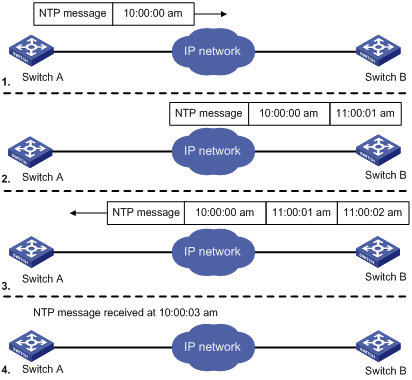
The process of system clock synchronization is as follows:
l Switch A sends Switch B an NTP message, which is timestamped when it leaves Switch A. The time stamp is 10:00:00 am (T1).
l When this NTP message arrives at Switch B, it is timestamped by Switch B. The timestamp is 11:00:01 am (T2).
l When the NTP message leaves Switch B, Switch B timestamps it. The timestamp is 11:00:02 am (T3).
l When Switch A receives the NTP message, the local time of Switch A is 10:00:03 am (T4).
Up to now, Switch A has sufficient information to calculate the following two important parameters:
l The roundtrip delay of NTP message: Delay = (T4–T1) – (T3-T2) = 2 seconds.
l Time difference between Switch A and Switch B: Offset = ((T2-T1) + (T3-T4))/2 = 1 hour.
Based on these parameters, Switch A can synchronize its own clock to the clock of Switch B.
This is only a rough description of the work mechanism of NTP. For details, refer to RFC 1305.
NTP Message Format
NTP uses two types of messages, clock synchronization message and NTP control message. An NTP control message is used in environments where network management is needed. As it is not a must for clock synchronization, it will not be discussed in this document.
![]()
All NTP messages mentioned in this document refer to NTP clock synchronization messages.
A clock synchronization message is encapsulated in a UDP message, in the format shown in Figure 1-2.
Figure 1-2 Clock synchronization message format
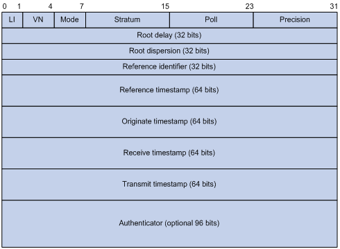
Main fields are described as follows:
l LI: 2-bit leap indicator. When set to 11, it warns of an alarm condition (clock unsynchronized); when set to any other value, it is not to be processed by NTP.
l VN: 3-bit version number, indicating the version of NTP. The latest version is version 3.
l Mode: a 3-bit code indicating the work mode of NTP. This field can be set to these values: 0 – reserved; 1 – symmetric active; 2 – symmetric passive; 3 – client; 4 – server; 5 – broadcast or multicast; 6 – NTP control message; 7 – reserved for private use.
l Stratum: an 8-bit integer indicating the stratum level of the local clock, with the value ranging from 1 to 16. The clock precision decreases from stratum 1 through stratum 16. A stratum 1 clock has the highest precision, and a stratum 16 clock is not synchronized and cannot be used as a reference clock.
l Poll: 8-bit signed integer indicating the poll interval, namely the maximum interval between successive messages.
l Precision: an 8-bit signed integer indicating the precision of the local clock.
l Root Delay: roundtrip delay to the primary reference source.
l Root Dispersion: the maximum error of the local clock relative to the primary reference source.
l Reference Identifier: Identifier of the particular reference source.
l Reference Timestamp: the local time at which the local clock was last set or corrected.
l Originate Timestamp: the local time at which the request departed the client for the service host.
l Receive Timestamp: the local time at which the request arrived at the service host.
l Transmit Timestamp: the local time at which the reply departed the service host for the client.
l Authenticator: authentication information.
Operation Modes of NTP
Switches running NTP can implement clock synchronization in one of the following modes:
Server/client mode
Figure 1-3 Server/client mode
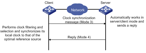
When working in the server/client mode, a client sends a clock synchronization message to servers, with the Mode field in the message set to 3 (client mode). Upon receiving the message, the servers automatically work in the server mode and send a reply, with the Mode field in the messages set to 4 (server mode). Upon receiving the replies from the servers, the client performs clock filtering and selection, and synchronizes its local clock to that of the optimal reference source.
In this mode, a client can be synchronized to a server, but not vice versa.
Symmetric peers mode
Figure 1-4 Symmetric peers mode
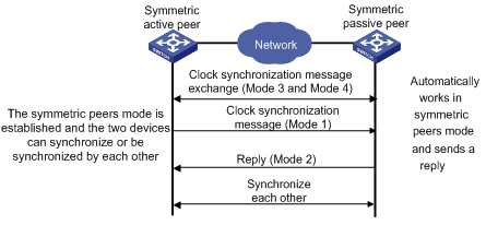
A switch working in the symmetric active mode periodically sends clock synchronization messages, with the Mode field in the message set to 1 (symmetric active); the switch that receives this message automatically enters the symmetric passive mode and sends a reply, with the Mode field in the message set to 2 (symmetric passive). By exchanging messages, the symmetric peers mode is established between the two switches. Then, the two switches can synchronize, or be synchronized by, each other. If the clocks of both switches have been already synchronized, the switch whose local clock has a lower stratum level will synchronize the clock of the other switch.
Broadcast mode
Figure 1-5 Broadcast mode
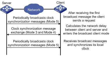
In the broadcast mode, a server periodically sends clock synchronization messages to the broadcast address 255.255.255.255, with the Mode field in the messages set to 5 (broadcast mode). Clients listen to the broadcast messages from servers. After a client receives the first broadcast message, the client and the server start to exchange messages, with the Mode field set to 3 (client mode) and 4 (server mode) to calculate the network delay between client and the server. Then, the client enters the broadcast client mode and continues listening to broadcast messages, and synchronizes its local clock based on the received broadcast messages.
Multicast mode
Figure 1-6 Multicast mode
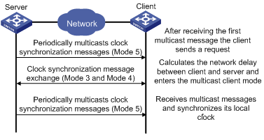
In the multicast mode, a server periodically sends clock synchronization messages to the user-configured multicast address, or, if no multicast address is configured, to the default NTP multicast address 224.0.1.1, with the Mode field in the messages set to 5 (multicast mode). Clients listen to the multicast messages from servers. After a client receives the first multicast message, the client and the server start to exchange messages, with the Mode field set to 3 (client mode) and 4 (server mode) to calculate the network delay between client and the server. Then, the client enters the multicast client mode and continues listening to multicast messages, and synchronizes its local clock based on the received multicast messages.
![]()
In symmetric peers mode, broadcast mode and multicast mode, the client (or the symmetric active peer) and the server (the symmetric passive peer) can work in the specified NTP working mode only after they exchange NTP messages with the Mode field being 3 (client mode) and the Mode field being 4 (server mode). During this message exchange process, NTP clock synchronization can be implemented.
NTP Configuration Task list
Complete the following tasks to configure NTP:
|
Task |
Remarks |
|
Required |
|
|
Optional |
|
|
Optional |
|
|
Optional |
Configuring the Operation Modes of NTP
Switches can implement clock synchronization in one of the following modes:
l Server/client mode
l Symmetric mode
l Broadcast mode
l Multicast mode
For the server/client mode or symmetric mode, you need to configure only clients or symmetric-active peers; for the broadcast or multicast mode, you need to configure both servers and clients.
![]()
A single switch can have a maximum of 128 associations at the same time, including static associations and dynamic associations. A static association refers to an association that a user has manually created by using an NTP command, while a dynamic association is a temporary association created by the system during operation. A dynamic association will be removed if the system fails to receive messages from it over a specific long time. In the server/client mode, for example, when you carry out a command to synchronize the time to a server, the system will create a static association, and the server will just respond passively upon the receipt of a message, rather than creating an association (static or dynamic). In the symmetric mode, static associations will be created at the symmetric-active peer side, and dynamic associations will be created at the symmetric-passive peer side; In the broadcast or multicast mode, static associations will be created at the server side, and dynamic associations will be created at the client side.
Configuring NTP Server/Client Mode
For switches working in the server/client mode, you only need to make configurations on the clients, and not on the servers.
Follow these steps to configure an NTP client:
|
To do… |
Use the command… |
Remarks |
|
Enter system view |
system-view |
— |
|
Specify an NTP server for the switch |
ntp-service unicast-server { ip-address | server-name } [ authentication-keyid keyid | priority | source-interface interface-type interface-number | version number ] * |
Required No NTP server is specified by default. |
![]()
l In the ntp-service unicast-server command, ip-address must be a host address, rather than a broadcast address, a multicast address or the IP address of the local clock.
l When the interface sending the NTP packet is specified by the source-interface argument, the source IP address of the NTP packet will be configured as the primary IP address of the specified interface.
l A switch can act as a server to synchronize the clock of other switches only after its clock has been synchronized. If the clock of a server has a stratum level higher than or equal to that of a client’s clock, the client will not synchronize its clock to the server’s.
l You can configure multiple servers by repeating the ntp-service unicast-server command. The clients will choose the optimal reference source.
Configuring the NTP Symmetric Mode
For switches working in the symmetric mode, you need to specify a symmetric-passive on a symmetric-active peer.
Following these steps to configure a symmetric-active switch:
|
To do… |
Use the command… |
Remarks |
|
Enter system view |
system-view |
— |
|
Specify a symmetric-passive peer for the switch |
ntp-service unicast-peer { ip-address | peer-name } [ authentication-keyid keyid | priority | source-interface interface-type interface-number | version number ] * |
Required No symmetric-passive peer is specified by default. |
![]()
l In the symmetric mode, you should use any NTP configuration command in Configuring the Operation Modes of NTP to enable NTP; otherwise, a symmetric-passive peer will not process NTP packets from a symmetric-active peer.
l In the ntp-service unicast-peer command, ip-address must be a host address, rather than a broadcast address, a multicast address or the IP address of the local clock.
l When the interface used to send NTP messages is specified by the source-interface argument, the source IP address of the NTP message will be configured as the primary IP address of the specified interface.
l Typically, at least one of the symmetric-active and symmetric-passive peers has been synchronized; otherwise the clock synchronization will not proceed.
l You can configure multiple symmetric-passive peers by repeating the ntp-service unicast-peer command.
Configuring NTP Broadcast Mode
The broadcast server periodically sends NTP broadcast messages to the broadcast address 255.255.255.255. After receiving the messages, the switch working in NTP broadcast mode sends a reply and synchronizes its local clock.
For switches working in the broadcast mode, you need to configure both the server and clients. Because an interface need to be specified on the broadcast server for sending NTP broadcast messages and an interface also needs to be specified on each broadcast client for receiving broadcast messages, the NTP broadcast mode can be configured only in the specific interface view.
Configuring a broadcast client
|
To do… |
Use the command… |
Remarks |
|
Enter system view |
system-view |
— |
|
Enter interface view |
interface interface-type interface-number |
Required Enter the interface used to receive NTP broadcast messages |
|
Configure the switch to work in the NTP broadcast client mode |
ntp-service broadcast-client |
Required |
Configuring the broadcast server
|
To do… |
Use the command… |
Remarks |
|
Enter system view |
system-view |
— |
|
Enter interface view |
interface interface-type interface-number |
Enter the interface used to send NTP broadcast messages |
|
Configure the switch to work in the NTP broadcast server mode |
ntp-service broadcast-server [ authentication-keyid keyid | version number ]* |
Required |
![]()
Configuring NTP Multicast Mode
The multicast server periodically sends NTP multicast messages to multicast clients, which send replies after receiving the messages and synchronize their local clocks.
For switches working in the multicast mode, you need to configure both the server and clients. The NTP multicast mode must be configured in the specific interface view.
Configuring a multicast client
|
To do… |
Use the command… |
Remarks |
|
Enter system view |
system-view |
— |
|
Enter interface view |
interface interface-type interface-number |
Enter the interface used to receive NTP multicast messages |
|
Configure the switch to work in the NTP multicast client mode |
ntp-service multicast-client [ ip-address ] |
Required |
Configuring the multicast server
|
To do… |
Use the command… |
Remarks |
|
Enter system view |
system-view |
— |
|
Enter interface view |
interface interface-type interface-number |
Enter the interface used to send NTP multicast message |
|
Configure the switch to work in the NTP multicast server mode |
ntp-service multicast-server [ ip-address ] [ authentication-keyid keyid | ttl ttl-number | version number ] * |
Required |
![]()
l A multicast server can synchronize broadcast clients only after its clock has been synchronized.
l You can configure up to 1024 multicast clients, among which 128 can take effect at the same time.
Configuring Optional Parameters of NTP
Configuring the Interface to Send NTP Messages
After you specify the interface used to send NTP messages, the source IP address of the NTP message will be configured as the primary IP address of the specified interface.
Following these steps to configure the interface used to send NTP messages:
|
To do… |
Use the command… |
Remarks |
|
Enter system view |
system-view |
— |
|
Configure the interface used to send NTP messages |
ntp-service source-interface interface-type interface-number |
Required |
![]()
If you have specified an interface in the ntp-service unicast-server or ntp-service unicast-peer command, this interface will be used for sending NTP messages.
Disabling an Interface from Receiving NTP Messages
|
To do… |
Use the command… |
Remarks |
|
Enter system view |
system-view |
— |
|
Enter interface view |
interface interface-type interface-number |
— |
|
Disable the interface from receiving NTP messages |
ntp-service in-interface disable |
Required An interface is enabled to receive NTP messages by default |
Configuring the Maximum Number of Dynamic Sessions Allowed
|
To do… |
Use the command… |
Remarks |
|
Enter system view |
system-view |
— |
|
Configure the maximum number of dynamic sessions allowed to be established locally |
ntp-service max-dynamic-sessions number |
Required 100 by default |
Configuring Access-Control Rights
With the following command, you can configure the NTP service access-control right to the local switch. There are four access-control rights, as follows:
l query: control query permitted. This level of right permits the peer switch to perform control query to the NTP service on the local switch but does not permit the peer switch to synchronize its clock to the local switch. The so-called “control query” refers to query of some states of the NTP service, including alarm information, authentication status, clock source information, and so on.
l synchronization: server access only. This level of right permits the peer switch to synchronize its clock to the local switch but does not permit the peer switch to perform control query.
l server: server access and query permitted. This level of right permits the peer switch to perform synchronization and control query to the local switch but does not permit the local switch to synchronize its clock to the peer switch.
l peer: full access. This level of right permits the peer switch to perform synchronization and control query to the local switch and also permits the local switch to synchronize its clock to the peer switch.
From the highest NTP service access-control right to the lowest one are peer, server, synchronization, and query. When a switch receives an NTP request, it will perform an access-control right match and will use the first matched right.
Configuration Prerequisites
Prior to configuring the NTP service access-control right to the local switch, you need to create and configure an ACL associated with the access-control right. For the configuration of ACL, refer to the ACL in H3C WX6103 Access Controller Switch Interface Board Configuration Guide.
Configuration Procedure
Follow these steps to configure the NTP service access-control right to the local switch:
|
To do… |
Use the command… |
Remarks |
|
Enter system view |
system-view |
— |
|
Configure the NTP service access-control right to the local switch |
ntp-service access { peer | query | server | synchronization } acl-number |
Required peer by default |
![]()
Configuring NTP Authentication
Configuration Prerequisites
The configuration NTP authentication involves configuration tasks to be implemented on the client and on the server.
When configuring the NTP authentication feature, pay attention to the following principles:
l For all synchronization modes, when you enable the NTP authentication feature, you should configure an authentication key and specify it as a trusted key. Namely, the ntp-service authentication enable command must work together with the ntp-service authentication-keyid command and the ntp-service reliable authentication-keyid command. Otherwise, the NTP authentication function cannot be normally enabled.
l For the server/client mode or symmetric mode, you need to associate the specified authentication key on the client (symmetric-active peer if in the symmetric peer mode) with the corresponding NTP server (symmetric-passive peer if in the symmetric peer mode). Otherwise, the NTP authentication feature cannot be normally enabled.
l For the broadcast server mode or multicast server mode, you need to associate the specified authentication key on the broadcast server or multicast server with the corresponding NTP server. Otherwise, the NTP authentication feature cannot be normally enabled.
l For the server/client mode, if the NTP authentication feature has not been enabled for the client, the client can synchronize with the server regardless the NTP authentication feature has been enabled for the server or not.
l For all synchronization modes, the server side and the client side must be consistently configured.
Configuration Procedure
Configuring NTP authentication for a client
Follow these steps to configure NTP authentication for a client:
|
To do… |
Use the command… |
Remarks |
|
Enter system view |
system-view |
— |
|
Enable NTP authentication |
ntp-service authentication enable |
Required Disabled by default |
|
Configure an NTP authentication key |
ntp-service authentication-keyid keyid authentication-mode md5 value |
Required No NTP authentication key by default |
|
Configure the key as a trusted key |
ntp-service reliable authentication-keyid keyid |
Required No authentication key is configured to be trusted by default |
|
Associate the specified key with an NTP server |
Server/client mode: ntp-service unicast-server { ip-address | server-name } authentication-keyid keyid |
Required You can associate a non-existing key with an NTP server. To enable NTP authentication, you must configure the key and specify it as a trusted key after associating the key with the NTP server. |
|
Symmetric peers mode: ntp-service unicast-peer { ip-address | peer-name } authentication-keyid keyid |
![]()
After you enable the NTP authentication feature for the client, make sure that you configure for the client an authentication key that is the same as on the server and specify that the authentication is trusted; otherwise, the client cannot be synchronized to the server.
Configuring NTP authentication for a server
Follow these steps to configure NTP authentication for a server:
|
To do… |
Use the command… |
Remarks |
|
Enter system view |
system-view |
— |
|
Enable NTP authentication |
ntp-service authentication enable |
Required Disabled by default |
|
Configure an NTP authentication key |
ntp-service authentication-keyid keyid authentication-mode md5 value |
Required No NTP authentication key by default |
|
Configure the key as a trusted key |
ntp-service reliable authentication-keyid keyid |
Required No authentication key is configured to be trusted by default |
|
Enter interface view |
interface interface-type interface-number |
— |
|
Associate the specified key with an NTP server |
Broadcast server mode: ntp-service broadcast-server authentication-keyid keyid |
Required You can associate a non-existing key with an NTP server. To enable NTP authentication, you must configure the key and specify it as a trusted key after associating the key with the NTP server. |
|
Multicast server mode: ntp-service multicast-server authentication-keyid keyid |
![]()
The procedure of configuring NTP authentication on a server is the same as that on a client, and the same authentication key must be configured on both the server and client sides.
Displaying and Maintaining NTP
|
To do… |
Use the command… |
Remarks |
|
View the information of NTP service status |
display ntp-service status |
Available in any view |
|
View the information of NTP sessions |
display ntp-service sessions [ verbose ] |
Available in any view |
|
View the brief information of the NTP servers from the local switch back to the primary reference source |
display ntp-service trace |
Available in any view |
NTP Configuration Examples
Configuring NTP Server/Client Mode
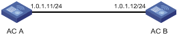
Network requirements
l The local clock of AC A is to be used as a reference source, with the stratum level of 2.
l AC B works in the server/client mode and AC A is to be used as the NTP server of AC B.
Network diagram
Figure 1-7 Network diagram for NTP server/client mode configuration
Configuration procedure
1) Configuration on AC A:
# Specify the local clock as the reference source, with the stratum level of 2.
<AC A> system-view
[AC A] ntp-service refclock-master 2
2) Configuration on AC B:
# View the NTP status of AC B before clock synchronization.
<AC B> display ntp-service status
Clock status: unsynchronized
Clock stratum: 16
Reference clock ID: none
Nominal frequency: 100.0000 Hz
Actual frequency: 100.0000 Hz
Clock precision: 2^7
Clock offset: 0.0000 ms
Root delay: 0.00 ms
Root dispersion: 0.00 ms
Peer dispersion: 0.00 ms
Reference time: 00:00:00.000 UTC Jan 1 1900 (00000000.00000000)
# Specify AC A as the NTP server of AC B so that AC B is synchronized to AC A.
<AC B> system-view
[AC B] ntp-service unicast-server 1.0.1.11
# View the NTP status of AC B after clock synchronization.
[AC B] display ntp-service status
Clock status: synchronized
Clock stratum: 3
Reference clock ID: 1.0.1.11
Nominal frequency: 100.0000 Hz
Actual frequency: 100.0000 Hz
Clock precision: 2^7
Clock offset: 0.0000 ms
Root delay: 31.00 ms
Root dispersion: 1.05 ms
Peer dispersion: 7.81 ms
Reference time: 14:53:27.371 UTC Apr 20 2007 (C6D94F67.5EF9DB22)
As shown above, AC B has been synchronized to AC A, and the clock stratum level of AC B is 3, while that of AC A is 2.
# View the NTP session information of AC B, which shows that an association has been set up between AC B and AC A.
[AC B] display ntp-service sessions
source reference stra reach poll now offset delay disper
**************************************************************************
[12345] 1.0.1.11 127.127.1.0 2 63 64 3 -75.5 31.0 16.5
note: 1 source(master),2 source(peer),3 selected,4 candidate,5 configured
Total associations : 1
Configuring the NTP Symmetric Mode
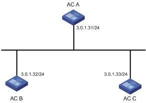
Network requirements
l The local clock of AC A is to be configured as a reference source, with the stratum level of 2.
l AC B works in the client mode and AC A is to be used as the NTP server of AC B.
l AC C works in the symmetric-active mode and AC B will act as peer of AC C. AC C is the symmetric-active peer while AC B is the symmetric-passive peer.
Network diagram
Figure 1-8 Network diagram for NTP symmetric peers mode configuration
Configuration procedure
1) Configuration on AC A:
# Specify the local clock as the reference source, with the stratum level of 2.
<AC A> system-view
[AC A] ntp-service refclock-master 2
2) Configuration on AC B:
# Specify AC A as the NTP server of AC B.
<AC B> system-view
[AC B] ntp-service unicast-server 3.0.1.31
3) Configuration on AC C (after AC B is synchronized to AC A):
# Specify the local clock as the reference source, with the stratum level of 1.
<AC C> system-view
[AC C] ntp-service refclock-master 1
# Configure AC B as a symmetric peer after local synchronization.
[AC C] ntp-service unicast-peer 3.0.1.32
In the step above, AC B and AC C are configured as symmetric peers, with AC C in the symmetric-active mode and AC B in the symmetric-passive mode. Because the stratum level of AC C is 1 while that of AC B is 3, AC B is synchronized to AC C.
# View the NTP status of AC B after clock synchronization.
[AC B] display ntp-service status
Clock status: synchronized
Clock stratum: 2
Reference clock ID: 3.0.1.33
Nominal frequency: 100.0000 Hz
Actual frequency: 100.0000 Hz
Clock precision: 2^7
Clock offset: -21.1982 ms
Root delay: 15.00 ms
Root dispersion: 775.15 ms
Peer dispersion: 34.29 ms
Reference time: 15:22:47.083 UTC Apr 20 2007 (C6D95647.153F7CED)
As shown above, AC B has been synchronized to AC C, and the clock stratum level of AC B is 2, while that of AC C is 1.
# View the NTP session information of AC B, which shows that an association has been set up between AC B and AC C.
[AC B] display ntp-service sessions
source reference stra reach poll now offset delay disper
**************************************************************************
[245] 3.0.1.31 127.127.1.0 2 15 64 24 10535.0 19.6 14.5
[1234] 3.0.1.33 LOCL 1 14 64 27 -77.0 16.0 14.8
note: 1 source(master),2 source(peer),3 selected,4 candidate,5 configured
Total associations : 2
Configuring NTP Broadcast Mode
Network requirements
l AC B’s local clock is to be used as a reference source, with the stratum level of 2.
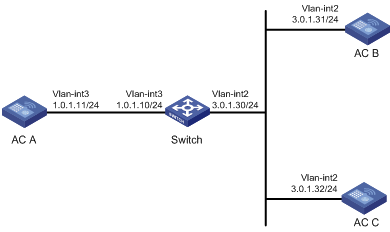
l AC B works in the broadcast server mode and sends out broadcast messages from VLAN-interface 2.
l AC A and AC C work in the broadcast client mode. AC A listens to broadcast messages through VLAN-interface 3, while AC C listens to broadcast messages through VLAN-interface 2.
Network diagram
Figure 1-9 Network diagram for NTP broadcast mode configuration
Configuration procedure
1) Configuration on AC B:
# Specify the local clock as the reference source, with the stratum level of 2.
<AC B> system-view
[AC B] ntp-service refclock-master 2
# Configure AC B to work in the broadcast server mode and send broadcast messages through VLAN-interface 2.
[AC B] interface vlan-interface 2
[AC B-Vlan-interface2] ntp-service broadcast-server
2) Configuration on AC C:
# Configure AC C to work in the broadcast client mode and receive broadcast messages on VLAN-interface 2.
<AC C> system-view
[AC C] interface vlan-interface 2
[AC C-Vlan-interface2] ntp-service broadcast-client
3) Configuration on AC A:
# Configure AC A to work in the broadcast client mode and receive broadcast messages on VLAN-interface 3.
<AC A> system-view
[AC A] interface vlan-interface 3
[AC A-Vlan-interface3] ntp-service broadcast-client
Because AC A and AC B are on different subnets, AC A cannot receive the broadcast messages from AC B and AC C gets synchronized upon receiving a broadcast message from AC B.
# View the NTP status of AC C after clock synchronization.
[AC C-Vlan-interface2] display ntp-service status
Clock status: synchronized
Clock stratum: 3
Reference clock ID: 3.0.1.31
Nominal frequency: 100.0000 Hz
Actual frequency: 100.0000 Hz
Clock precision: 2^7
Clock offset: 0.0000 ms
Root delay: 31.00 ms
Root dispersion: 8.31 ms
Peer dispersion: 34.30 ms
Reference time: 16:01:51.713 UTC Apr 20 2007 (C6D95F6F.B6872B02)
As shown above, AC C has been synchronized to AC B, and the clock stratum level of AC C is 3, while that of AC B is 2.
# View the NTP session information of AC C, which shows that an association has been set up between AC C and AC B.
[AC C-Vlan-interface2] display ntp-service sessions
source reference stra reach poll now offset delay disper
**************************************************************************
[1234] 3.0.1.31 127.127.1.0 2 254 64 62 -16.0 32.0 16.6
note: 1 source(master),2 source(peer),3 selected,4 candidate,5 configured
Total associations : 1
Configuring NTP Multicast Mode
Network requirements
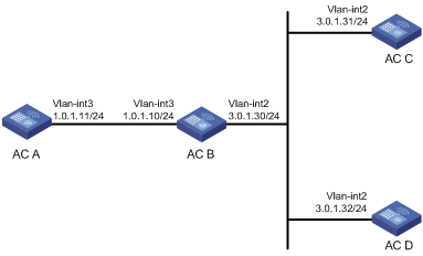
l AC C’s local clock is to be used as a reference source, with the stratum level of 2.
l AC C works in the multicast server mode and sends out multicast messages from VLAN-interface 2.
l AC D and AC A work in the multicast client mode. AC A receives multicast messages through VLAN-interface 3, while AC D receives multicast messages through VLAN-interface 2.
Network diagram
Figure 1-10 Network diagram for NTP multicast mode configuration
Configuration procedure
1) Configuration on AC C:
# Specify the local clock as the reference source, with the stratum level of 2.
<AC C> system-view
[AC C] ntp-service refclock-master 2
# Configure AC C to work in the multicast server mode and send multicast messages through VLAN-interface 2.
[AC C] interface vlan-interface 2
[AC C-Vlan-interface2] ntp-service multicast-server
2) Configuration on AC D:
# Configure AC D to work in the multicast client mode and receive multicast messages on VLAN-interface 2.
<AC D> system-view
[AC D] interface vlan-interface 2
[AC D-Vlan-interface2] ntp-service multicast-client
Because AC D and AC C are on the same subnet, AC D can receive the multicast messages from AC C without being IGMP-enabled and can be synchronized to AC C.
# View the NTP status of AC D after clock synchronization.
[AC D-Vlan-interface2] display ntp-service status
Clock status: synchronized
Clock stratum: 3
Reference clock ID: 3.0.1.31
Nominal frequency: 100.0000 Hz
Actual frequency: 100.0000 Hz
Clock precision: 2^7
Clock offset: 0.0000 ms
Root delay: 31.00 ms
Root dispersion: 8.31 ms
Peer dispersion: 34.30 ms
Reference time: 16:01:51.713 UTC Apr 20 2007 (C6D95F6F.B6872B02)
As shown above, AC D has been synchronized to AC C, and the clock stratum level of AC D is 3, while that of AC C is 2.
# View the NTP session information of AC D, which shows that an association has been set up between AC D and AC C.
[AC D-Vlan-interface2] display ntp-service sessions
source reference stra reach poll now offset delay disper
**************************************************************************
[1234] 3.0.1.31 127.127.1.0 2 254 64 62 -16.0 31.0 16.6
note: 1 source(master),2 source(peer),3 selected,4 candidate,5 configured
Total associations : 1
3) Configuration on AC B:
Because AC A and AC C are on different subnets, you must enable IGMP on AC B before AC A can receive multicast messages from AC C.
# Enable IP multicast routing and IGMP.
<AC B> system-view
[AC B] multicast routing-enable
[AC B] interface vlan-interface 2
[AC B-Vlan-interface2] pim dm
[AC B-Vlan-interface2] quit
[AC B] vlan 3
[AC B-vlan3] port GigabitEthernet 0/0/1
[AC B-vlan3] quit
[AC B] interface vlan-interface 3
[AC B-Vlan-interface3] igmp enable
[AC B-Vlan-interface3] quit
[AC B] interface GigabitEthernet 0/0/1
[AC B-GigabitEthernet0/0/1] igmp-snooping static-group 224.0.1.1 vlan 3
4) Configuration on AC A:
# Enable IP multicast routing and IGMP.
<AC A> system-view
[AC A] interface vlan-interface 3
# Configure AC A to work in the multicast client mode and receive multicast messages on VLAN-interface 3.
[AC A-Vlan-interface3] ntp-service multicast-client
# View the NTP status of AC A after clock synchronization.
[AC A-Vlan-interface3] display ntp-service status
Clock status: synchronized
Clock stratum: 3
Reference clock ID: 3.0.1.31
Nominal frequency: 100.0000 Hz
Actual frequency: 100.0000 Hz
Clock precision: 2^7
Clock offset: 0.0000 ms
Root delay: 40.00 ms
Root dispersion: 10.83 ms
Peer dispersion: 34.30 ms
Reference time: 16:02:49.713 UTC Apr 20 2007 (C6D95F6F.B6872B02)
As shown above, AC A has been synchronized to AC C, and the clock stratum level of AC A is 3, while that of AC C is 2.
# View the NTP session information of AC A, which shows that an association has been set up between AC A and AC C.
[AC A-Vlan-interface3] display ntp-service sessions
source reference stra reach poll now offset delay disper
**************************************************************************
[1234] 3.0.1.31 127.127.1.0 2 255 64 26 -16.0 40.0 16.6
note: 1 source(master),2 source(peer),3 selected,4 candidate,5 configured
Total associations : 1
![]()
Refer to the Multicast Protocol in H3C WX6103 Access Controller Switch Interface Board Configuration Guide for detailed description of the multicast function.
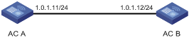
Configuring NTP Server/Client Mode with Authentication
Network requirements
l The local clock of AC A is to be configured as a reference source, with the stratum level of 2.
l AC B works in the client mode and AC A is to be used as the NTP server of AC B, with AC B as the client.
l NTP authentication is to be enabled for AC A and AC B at the same time.
Network diagram
Figure 1-11 Network diagram for configuration of NTP server/client mode with authentication
Configuration procedure
1) Configuration on AC A:
# Specify the local clock as the reference source, with the stratum level of 2.
<AC A> system-view
[AC A] ntp-service refclcok-master 2
2) Configuration on AC B:
<AC B> system-view
# Enable NTP authentication on AC B.
[AC B] ntp-service authentication enable
# Set an authentication key.
[AC B] ntp-service authentication-keyid 42 authentication-mode md5 aNiceKey
# Specify the key as key as a trusted key.
[AC B] ntp-service reliable authentication-keyid 42
# Specify AC A as the NTP server.
[AC B] ntp-service unicast-server 1.0.1.11 authentication-keyid 42
Before AC B can synchronize its clock to that of AC A, you need to enable NTP authentication for AC A.
Perform the following configuration on AC A:
# Enable NTP authentication.
[AC A] ntp-service authentication enable
# Set an authentication key.
[AC A] ntp-service authentication-keyid 42 authentication-mode md5 aNiceKey
# Specify the key as key as a trusted key.
[AC A] ntp-service reliable authentication-keyid 42
# View the NTP status of AC B after clock synchronization.
[AC B] display ntp-service status
Clock status: synchronized
Clock stratum: 3
Reference clock ID: 1.0.1.11
Nominal frequency: 100.0000 Hz
Actual frequency: 100.0000 Hz
Clock precision: 2^7
Clock offset: 0.0000 ms
Root delay: 31.00 ms
Root dispersion: 1.05 ms
Peer dispersion: 7.81 ms
Reference time: 14:53:27.371 UTC Apr 20 2007 (C6D94F67.5EF9DB22)
As shown above, AC B has been synchronized to AC A, and the clock stratum level of AC B is 3, while that of AC A is 2.
# View the NTP session information of AC B, which shows that an association has been set up AC B and AC A.
[AC B] display ntp-service sessions
source reference stra reach poll now offset delay disper
**************************************************************************
[12345] 1.0.1.11 127.127.1.0 2 63 64 3 -75.5 31.0 16.5
note: 1 source(master),2 source(peer),3 selected,4 candidate,5 configured
Total associations : 1
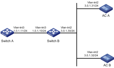
Configuring NTP Broadcast Mode with Authentication
Network requirements
l AC A’s local clock is to be used as a reference source, with the stratum level of 3.
l AC A works in the broadcast server mode and sends out broadcast messages from VLAN-interface 2.
l AC B works in the broadcast client mode and receives broadcast messages through VLAN-interface 2.
l NTP authentication is enabled on both AC A and AC B.
Network diagram
Figure 1-12 Network diagram for configuration of NTP broadcast mode with authentication
Configuration procedure
1) Configuration on AC A:
# Specify the local clock as the reference source, with the stratum level of 3.
<AC A> system-view
[AC A] ntp-service refclock-master 3
# Configure NTP authentication
[AC A] ntp-service authentication enable
[AC A] ntp-service authentication-keyid 88 authentication-mode md5 123456
[AC A] ntp-service reliable authentication-keyid 88
# Specify AC A as an NTP broadcast server, and specify an authentication key.
[AC A] interface vlan-interface 2
[AC A-Vlan-interface2] ntp-service broadcast-server authentication-keyid 88
2) Configuration on AC B:
# Configure NTP authentication
<AC B> system-view
[AC B] ntp-service authentication enable
[AC B] ntp-service authentication-keyid 88 authentication-mode md5 123456
[AC B] ntp-service reliable authentication-keyid 88
# Configure AC B to work in the NTP broadcast client mode
[AC B] interface vlan-interface 2
[AC B-Vlan-interface2] ntp-service broadcast-client
Now, AC B can listen to the broadcast messages through VLAN-interface 2, and AC A can send broadcast messages through VLAN-interface 2. Upon receiving a broadcast message from AC A, AC B synchronizes its clock to that of AC A.
# View the NTP status of AC B after clock synchronization.
[AC B-Vlan-interface2] display ntp-service status
Clock status: synchronized
Clock stratum: 4
Reference clock ID: 3.0.1.31
Nominal frequency: 100.0000 Hz
Actual frequency: 100.0000 Hz
Clock precision: 2^7
Clock offset: 0.0000 ms
Root delay: 31.00 ms
Root dispersion: 8.31 ms
Peer dispersion: 34.30 ms
Reference time: 16:01:51.713 UTC Apr 20 2007 (C6D95F6F.B6872B02)
As shown above, AC B has been synchronized to AC A, and the clock stratum level of AC B is 3, while that of AC A is 2.
# View the NTP session information of AC B, which shows that an association has been set up between AC B and AC A.
[AC B-Vlan-interface2] display ntp-service sessions
source reference stra reach poll now offset delay disper
**************************************************************************
[1234] 3.0.1.31 127.127.1.0 3 254 64 62 -16.0 32.0 16.6
note: 1 source(master),2 source(peer),3 selected,4 candidate,5 configured
Total associations : 1