- Table of Contents
-
- H3C WX6103 Access Controller Switch Interface Board Configuration Guide-6W102
- 00-Preface
- 01-Login Configuration
- 02-VLAN Configuration
- 03-IP Addressing and IP Performance Configuration
- 04-QinQ-BPDU Tunneling Configuration
- 05-Port Correlation Configuration
- 06-Link Aggregation Configuration
- 07-MAC Address Table Management Configuration
- 08-Port Security Configuration
- 09-MSTP Configuration
- 10-IP Routing-GR Overview Configuration
- 11-IPv4 Routing Configuration
- 12-IP Source Guard Configuration
- 13-DLDP Configuration
- 14-Multicast Configuration
- 15-LLDP Configuration
- 16-sFlow Configuration
- 17-ARP Configuration
- 18-DHCP Configuration
- 19-ACL Configuration
- 20-QoS Configuration
- 21-Port Mirroring Configuration
- 22-UDP Helper Configuration
- 23-SNMP-RMON Configuration
- 24-NTP Configuration
- 25-DNS Configuration
- 26-File System Management Configuration
- 27-Information Center Configuration
- 28-System Maintaining and Debugging Configuration
- 29-NQA Configuration
- 30-SSH Configuration
- 31-SSL-HTTPS Configuration
- 32-PKI Configuration
- 33-Track Configuration
- 34-Acronyms
- 35-Index
- Related Documents
-
| Title | Size | Download |
|---|---|---|
| 15-LLDP Configuration | 119.51 KB |
Table of Contents
Performing Basic LLDP Configuration
Configuring the Parameters Concerning LLDPDU Sending
Displaying and Maintaining LLDP
When configuring LLDP, go to these sections for information you are interested in:
l LLDP Configuration Tasks List
l Performing Basic LLDP Configuration
l Displaying and Maintaining LLDP
![]()
The term switch in this document refers to a switch in a generic sense or an access controller configured with the switching function unless otherwise specified.
Introduction to LLDP
Overview
Link Layer Discovery Protocol (LLDP) operates on data link layer. It stores and maintains the information about the local device and the devices directly connected to it for network administrators to manage networks through NMS (network management systems). In LLDP, device information is encapsulated in LLDPDUs in the form of TLV (meaning type, length, and value) triplets and is exchanged between directly connected devices. Information in LLDPDUs received is restored in standard MIB (management information base).
LLDP Fundamental
LLDP operating mode
LLDP can operate in one of the following modes.
l TxRx mode. A port in this mode sends and receives LLDPDUs.
l Tx mode. A port in this mode only sends LLDPDUs.
l Rx mode. A port in this mode only receives LLDPDUs.
l Disable mode. A port in this mode does not send or receive LLDPDUs.
LLDP is initialized when an LLDP-enabled port changes to operate in another LLDP operating mode. To prevent LLDP from being initialized too frequently, LLDP undergoes a period before being initialized on an LLDP-enabled port when the port changes to operate in another LLDP operating mode. The period is known as initialization delay, which is determined by the re-initialization delay timer.
Sending LLDPDUs
An LLDP-enabled device operating in the TxRx mode or Tx mode sends LLDPDUs to its directly connected devices periodically. It also sends LLDPDUs when the local configuration changes to inform the neighboring devices of the change timely. In any of the two cases, an interval exists between two successive operations of sending LLDPDUs. This prevents the network from being overwhelmed by LLDPDUs even if the LLDP operating mode changes frequently.
To enable the neighboring devices to be informed of the existence of a device or an LLDP operating mode change (from the disable mode to TxRx mode, or from the Rx mode to Tx mode) timely, a device can invoke the fast sending mechanism. In this case, the interval to send LLDPDUs changes to one second. After the device sends specific number of LLDPDUs, the interval restores to the normal. (A neighbor is discovered when a device receives an LLDPDU and no information about the sender is locally available.)
Receiving LLDPDUs
An LLDP-enabled device operating in the TxRx mode or Rx mode checks the TLVs carried in the LLDPDUs it receives and saves the valid neighboring information. An LLDPDU also carries a TTL (time to live) setting with it. The information about a neighboring device maintained locally ages out when the corresponding TTL expires.
The TTL of the information about a neighboring device is determined by the following expression:
TTL multiplier × LLDPDU sending interval.
You can set the TTL by configuring the TTL multiplier. Note that the TTL can be up to 65535 seconds. TTLs longer than it will be rounded off to 65535 seconds.
TLV Types
TLVs encapsulated in LLDPDUs fall into these categories: basic TLV, organization defined TLV, and MED (media endpoint discovery) related TLV. Basic TLVs are the base of device management. Organization specific TLVs and MED related TLVs are used for enhanced device management. They are defined in standards or by organizations and are optional to LLDPDUs.
Basic LLDP TLVs
Table 1-1 lists the basic LLDP TLV types that are currently in use.
|
Type |
Description |
Remarks |
|
End of LLDPDU TLV |
Marks the end of an LLDPDU. |
Required for LLDP |
|
Chassis ID TLV |
Carries the bridge MAC address of the sender |
|
|
Port ID TLV |
Carries the sending port. For devices that do not send MED TLVs, port ID TLVs carry sending port name. For devices that send MED TLVs, port ID TLVs carry the MAC addresses of the sending ports or bridge MAC addresses (if the MAC addresses of the sending ports are unavailable). |
|
|
Time To Live TLV |
Carries the TTL of device information |
|
|
Port Description TLV |
Carries Ethernet port description |
Optional to LLDP |
|
System Name TLV |
Carries device name |
|
|
System Description TLV |
Carries system description |
|
|
System Capabilities TLV |
Carries information about system capabilities |
|
|
Management Address TLV |
Carries the management address, the corresponding port number, and OID (object identifier). If the management address is not configured, it is the IP address of the interface of the VLAN with the least VLAN ID among those permitted on the port. If the IP address of the VLAN interface is not configured, IP address 127.0.0.1 is used as the management address. |
Organization defined LLDP TLVs
1) LLDP TLVs defined in IEEE802.1 include the following:
l Port VLAN ID TLV, which carries port VLAN ID.
l Port and protocol VLAN ID TLV, which carries port protocol VLAN ID.
l VLAN name TLV, which carries port VLAN name.
l Protocol identity TLV, which carries types of the supported protocols.
![]()
Currently, protocol identity TLVs can only be received on H3C devices.
2) IEEE 802.3 defined LLDP TLVs include the following:
l MAC/PHY configuration/status TLV, which carries port configuration, such as port speed, duplex state, whether port speed auto-negotiation is supported, the state of auto-negotiation, current speed , and current duplex state.
l Power via MDI TLV, which carries information about power supply capabilities.
l Link aggregation TLV, which carries the capability and state of link aggregation.
l Maximum frame size TLV, which carries the maximum frame size supported, namely, MTU (maximum transmission unit).
MED related LLDP TLVs
l LLDP-MED capabilities TLV, which carries the MED type of the current device and the types of the LLDP MED TLVs that can be encapsulated in LLDPDUs.
l Network policy TLV, which carries port VLAN ID, supported applications (such as voice and video services), application priority, and the policy adopted.
l Extended power-via-MDI TLV, which carries the information about the power supply capability of the current device.
l Hardware revision TLV, which carries the hardware version of an MED device.
l Firmware revision TLV, which carries the firmware version of an MED device.
l Software revision TLV, which carries the software version of an MED device.
l Serial number TLV, which carries the serial number of an MED device.
l Manufacturer name TLV, which carries the manufacturer name of an MED device.
l Model name TLV, which carries the model of an MED device.
l Asset ID TLV, which carries the asset ID of an MED device. Asset ID is used for directory management and asset tracking.
l Location identification TLV, which carries the location identification of a device. Location identification can be used in location-based applications.
![]()
For detailed information about LLDP TLV, refer to IEEE 802.1AB-2005 and ANSI/TIA-1057.
Protocols and Standards
l IEEE 802.1AB-2005, Station and Media Access Control Connectivity Discovery
l ANSI/TIA-1057, Link Layer Discovery Protocol for Media Endpoint Devices
LLDP Configuration Tasks List
Complete these tasks to configure LLDP:
|
Task |
Remarks |
|
|
Basic LLDP configuration |
Required |
|
|
Optional |
||
|
Optional |
||
|
Optional |
||
|
Optional |
||
|
Optional |
||
Performing Basic LLDP Configuration
Enabling LLDP
Follow these steps to enable LLDP:
|
To do… |
Use the command… |
Remarks |
|
|
Enter system view |
system-view |
— |
|
|
Enable LLDP globally |
lldp enable |
Required Enabled by default |
|
|
Enter Ethernet interface view/port group view |
Enter Ethernet interface view |
interface interface-type interface-number |
Either of the two is required. Configuration performed in Ethernet interface view applies to the current port only; configuration performed in port group view applies to all the ports in the corresponding port group. |
|
Enter port group view |
port-group { aggregation agg-id | manual port-group-name } |
||
|
Enable LLDP |
lldp enable |
Optional By default, LLDP is enabled on a port. |
|
![]()
To make LLDP take effect, you need to enable it both globally and on the related ports.
Setting LLDP Operating Mode
Follow these steps to set LLDP operating mode:
|
To do… |
Use the command… |
Remarks |
|
|
Enter system view |
system-view |
— |
|
|
Set the initialization delay period |
lldp timer reinit-delay value |
Optional 2 seconds by default. |
|
|
Enter Ethernet interface view/port group view |
Enter Ethernet interface view |
interface interface-type interface-number |
Either of the two is required. Configuration performed in Ethernet interface view applies to the current port only; configuration performed in port group view applies to all the ports in the corresponding port group. |
|
Enter port group view |
port-group { aggregation agg-id | manual port-group-name } |
||
|
Set the LLDP operating mode |
lldp admin-status { disable | rx | tx | txrx } |
Optional TxRx by default. |
|
Configuring LLDPDU TLVs
Follow these steps to configure LLDPDU TLVs:
|
To do… |
Use the command… |
Remarks |
|
|
Enter system view |
system-view |
— |
|
|
Set the TTL multiplier |
lldp hold-multiplier value |
Optional 4 by default. |
|
|
Enter Ethernet interface view/port group view |
Enter Ethernet interface view |
interface interface-type interface-number |
Either of the two is required. Configuration performed in Ethernet interface view applies to the current port only; configuration performed in port group view applies to all the ports in the corresponding port group. |
|
Enter port group view |
port-group { aggregation agg-id | manual port-group-name } |
||
|
Enable LLDP TLV sending for specific types of LLDP TLVs |
lldp tlv-enable { basic-tlv { all | port-description | system-capability | system-description | system-name } | dot1-tlv { all | port-vlan-id | protocol-vlan-id [ vlan-id ] | vlan-name [ vlan-id ] } | dot3-tlv { all | link-aggregation | mac-physic | max-frame-size | power } | med-tlv { all | capability | location-id { civic-address device-type country-code { ca-type ca-value }&<1-10> | elin-address Tel-Number } | network-policy | power-over-ethernet | inventory } } |
Optional By default, all types of LLDP TLVs except location identification TLV are sent. |
|
|
Specify the management address and specify to send the management address through LLDPDUs |
lldp management-address-tlv [ ip-address ] |
Optional By default, the management address is sent through LLDPDUs, and the management address is the IP address of the interface of the VLAN with the least VLAN ID among those permitted on the port. If the IP address of the VLAN interface is not configured, IP address 127.0.0.1 is used as the management address. Refer to VLAN in H3C WX6103 Access Controller Switch Interface Board Configuration Guide for information about VLAN. |
|
![]()
l To enable MED related LLDP TLV sending, you need to enable LLDP-MED capabilities TLV sending first. Conversely, to disable LLDP-MED capabilities TLV sending, you need to disable the sending of other MED related LLDP TLVs.
l To disable MAC/PHY configuration/status TLV sending, you need to disable LLDP-MED capabilities TLV sending first.
l When executing the lldp tlv-enable command, specifying the all keyword for basic LLDP TLVs and organization defined LLDP TLVs (including IEEE 802.1 defined LLDP TLVs and IEEE 802.3 defined LLDP TLVs) enables sending of all the corresponding LLDP TLVs. For MED related LLDP TLVs, the all keyword enables sending of all the MED related LLDP TLVs except location identification TLVs.
l Enabling sending of LLDP-MED capabilities TLVs also enables sending of MAC/PHY configuration/status TLVs.
Enable LLDP Polling
With LLDP polling enabled, a device checks for the local configuration changes periodically. Upon detecting a configuration change, the device sends LLDPDUs to inform the neighboring devices of the change.
Follow these steps to enable LLDP polling:
|
To do… |
Use the command… |
Remarks |
|
|
Enter system view |
system-view |
— |
|
|
Enter Ethernet interface view/port group view |
Enter Ethernet interface view |
interface interface-type interface-number |
Either of the two is required. Configuration performed in Ethernet interface view applies to the current port only; configuration performed in port group view applies to all the ports in the corresponding port group. |
|
Enter port group view |
port-group { aggregation agg-id | manual port-group-name } |
||
|
Enable LLDP polling and set the polling interval |
lldp check-change-interval value |
Optional Disabled by default |
|
Configuring the Parameters Concerning LLDPDU Sending
Configuring time-related parameters
Follow these steps to set time-related parameters:
|
Use the command… |
Remarks |
|
|
Enter system view |
System-view |
— |
|
Set the interval to send LLDPDUs |
lldp timer tx-interval value |
Optional 30 seconds by default |
|
Set the delay period to send LLDPDUs |
lldp timer tx-delay value |
Optional 2 seconds by default |
![]()
To enable local device information to be updated on neighboring devices before being aged out, make sure the interval to send LLDPDUs is shorter than the TTL of the local device information.
Setting the number of the LLDPDUs to be sent when a new neighboring device is detected
|
To do… |
Use the command… |
Remarks |
|
Enter system view |
system-view |
— |
|
Set the number of the LLDPDUs to be sent successively when a new neighboring device is detected |
lldp fast-count value |
Optional 3 by default |
Configuring LLDP Trap
LLDP trap is used to notify NMS of the events such as new neighboring devices detected and link malfunctions.
LLDP traps are sent periodically and you can set the interval to send LLDP traps. In response to topology changes detected, a device sends LLDP traps according to the interval configured to inform the neighboring devices of the changes.
Follow these steps to configure LLDP trap:
|
To do… |
Use the command… |
Remarks |
|
|
Enter system view |
system-view |
— |
|
|
Enter Ethernet interface view/port group view |
Enter Ethernet interface view |
interface interface-type interface-number |
Either of the two is required. Configuration performed in Ethernet interface view applies to the current port only; configuration performed in port group view applies to all the ports in the corresponding port group. |
|
Enter port group view |
port-group { aggregation agg-id | manual port-group-name } |
||
|
Enable LLDP trap sending |
lldp notification remote-change enable |
Required Disabled by default |
|
|
Quit to system view |
quit |
— |
|
|
Set the interval to send LLDP traps |
lldp timer notification-interval value |
Optional 5 seconds by default |
|
Displaying and Maintaining LLDP
|
Use the command… |
Remarks |
|
|
Display the global LLDP information or the information contained in the LLDP TLVs to be sent through a port |
display lldp local-information [ global | interface interface-type interface-number ] |
Available in any view |
|
Display the information contained in the LLDP TLVs received through a port |
display lldp neighbor-information [ interface interface-type interface-number ] [ brief ] |
Available in any view |
|
Display LLDP statistics |
display lldp statistics [ global | interface interface-type interface-number ] |
Available in any view |
|
Display LLDP status of a port |
display lldp status [ interface interface-type interface-number ] |
Available in any view |
|
Display the types of the LLDP TLVs that are currently sent |
display lldp tlv-config [ interface interface-type interface-number ] |
Available in any view |
LLDP Configuration Example
LLDP Configuration Example
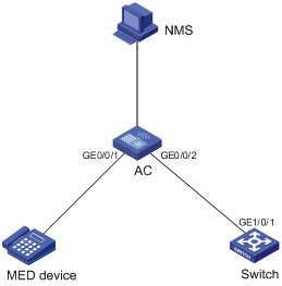
Network requirements
l The NMS and AC are located in the same Ethernet. An MED device and Switch are connected to GigabitEthernet 0/0/1 and GigabitEthernet 0/0/2 of AC.
l Enable LLDP on the ports of AC and Switch to monitor the link between AC and Switch and the link between AC and the MED device on the NMS.
Network diagram
Figure 1-1 Network diagram for LLDP configuration
Configuration procedure
1) Configure AC.
# Enter system view.
<AC> system-view
# Enable LLDP globally.
[AC] lldp enable
# Enable LLDP on GigabitEthernet 0/0/1 and GigabitEthernet 0/0/2, setting the LLDP operating mode to Rx.
[AC] interface GigabitEthernet0/0/1
[AC-GigabitEthernet0/0/1] lldp enable
[AC-GigabitEthernet0/0/1] lldp admin-status rx
[AC-GigabitEthernet0/0/1] quit
[AC] interface GigabitEthernet0/0/2
[AC-GigabitEthernet0/0/2] lldp enable
[AC-GigabitEthernet0/0/2] lldp admin-status rx
[AC-GigabitEthernet0/0/2] quit
2) Configure Switch.
# Enter system view.
<Switch> system-view
# Enable LLDP globally.
[Switch] lldp enable
# Enable LLDP on GigabitEthernet1/0/1, setting the LLDP operating mode to Tx.
[Switch] interface GigabitEthernet1/0/1
[Switch-GigabitEthernet1/0/1] lldp enable
[Switch-GigabitEthernet1/0/1] lldp admin-status tx
3) Verify the configuration.
# Display the global LLDP status and port LLDP status on AC.
<AC> display lldp status
Global status of LLDP : Enable
The current number of neighbors : 2
Neighbor information last changed time : 0 days, 0 hours, 4 minutes, 40 seconds
Transmit interval : 30s
Hold multiplier : 4
Reinit delay : 2s
Transmit delay : 2s
Trap interval : 5s
Fast start times : 3
Port 0 [GigabitEthernet0/0/1] :
Port status of LLDP : Enable
Admin status : Rx_Only
Trap flag : No
Roll time : 0s
Number of neighbors : 1
Number of MED neighbors : 1
Number of sent optional TLV : 0
Number of received unknown TLV : 0
Port 1 [GigabitEthernet0/0/2] :
Port status of LLDP : Enable
Admin status : Rx_Only
Trap flag : No
Roll time : 0s
Number of neighbors : 1
Number of MED neighbors : 0
Number of sent optional TLV : 0
Number of received unknown TLV : 3
# Tear down the link between AC and Switch and then display the global LLDP status and port LLDP status on AC.
<AC> display lldp status
Global status of LLDP : Enable
The current number of neighbors : 1
Neighbor information last changed time : 0 days, 0 hours, 5 minutes, 20 seconds
Transmit interval : 30s
Hold multiplier : 4
Reinit delay : 2s
Transmit delay : 2s
Trap interval : 5s
Fast start times : 3
Port 0 [GigabitEthernet0/0/1] :
Port status of LLDP : Enable
Admin status : Rx_Only
Trap flag : No
Roll time : 0s
Number of neighbors : 1
Number of MED neighbors : 1
Number of sent optional TLV : 0
Number of received unknown TLV : 5
Port 1 [GigabitEthernet0/0/2] :
Port status of LLDP : Enable
Admin status : Rx_Only
Trap flag : No
Roll time : 0s
Number of neighbors : 0
Number of MED neighbors : 0
Number of sent optional TLV : 0
Number of received unknown TLV : 0