- Table of Contents
-
- H3C WX6103 Access Controller Switch Interface Board Configuration Guide-6W102
- 00-Preface
- 01-Login Configuration
- 02-VLAN Configuration
- 03-IP Addressing and IP Performance Configuration
- 04-QinQ-BPDU Tunneling Configuration
- 05-Port Correlation Configuration
- 06-Link Aggregation Configuration
- 07-MAC Address Table Management Configuration
- 08-Port Security Configuration
- 09-MSTP Configuration
- 10-IP Routing-GR Overview Configuration
- 11-IPv4 Routing Configuration
- 12-IP Source Guard Configuration
- 13-DLDP Configuration
- 14-Multicast Configuration
- 15-LLDP Configuration
- 16-sFlow Configuration
- 17-ARP Configuration
- 18-DHCP Configuration
- 19-ACL Configuration
- 20-QoS Configuration
- 21-Port Mirroring Configuration
- 22-UDP Helper Configuration
- 23-SNMP-RMON Configuration
- 24-NTP Configuration
- 25-DNS Configuration
- 26-File System Management Configuration
- 27-Information Center Configuration
- 28-System Maintaining and Debugging Configuration
- 29-NQA Configuration
- 30-SSH Configuration
- 31-SSL-HTTPS Configuration
- 32-PKI Configuration
- 33-Track Configuration
- 34-Acronyms
- 35-Index
- Related Documents
-
| Title | Size | Download |
|---|---|---|
| 05-Port Correlation Configuration | 139.82 KB |
Table of Contents
1 Port Correlation Configuration
Performing Basic Ethernet Port Configuration
Enabling Flow Control on an Ethernet Port
Enabling Loopback Test on an Ethernet Port
Configuring the Broadcast/Multicast/Unknown Unicast Storm Suppression Ratio for an Ethernet Port
Enabling Forwarding of Jumbo Frames
Enabling Loopback Detection on an Ethernet Port
Configuring the Cable Type for an Ethernet Port
Testing the Cable on an Ethernet Port
Configuring the Storm Constrain Function on an Ethernet Port
Maintaining and Displaying an Ethernet Port
2 Port Isolation Configuration
Introduction to Port Isolation
Configuring an Isolation Group
Adding a Port to an Isolation Group
Port Isolation Configuration Example
![]()
The term switch in this document refers to a switch in a generic sense or an access controller configured with the switching function unless otherwise specified.
When configuring Ethernet ports, go to these sections for information you are interested in:
l Maintaining and Displaying an Ethernet Port
Ethernet Port Configuration
Complete the following tasks to configure an Ethernet port:
|
Task |
Remarks |
|
Optional |
|
|
Optional |
|
|
Optional |
|
|
Optional |
|
|
Optional |
|
|
Configuring the Broadcast/Multicast/Unknown Unicast Storm Suppression Ratio for an Ethernet Port |
Optional |
|
Optional |
|
|
Optional |
|
|
Optional |
|
|
Optional |
|
|
Configuring the Storm Constrain Function on an Ethernet Port |
Optional |
Performing Basic Ethernet Port Configuration
Three types of duplex modes are available to Ethernet ports:
l Full-duplex mode (full). Ports operating in this mode can send and receive packets simultaneously.
l Half-duplex mode (half). Ports operating in this mode can either send or receive packets at a given time.
l Auto-negotiation mode (auto). Ports operating in this mode determine their duplex mode through auto-negotiation.
Similarly, if you configure the transmission rate for an Ethernet port by using the speed command with the auto keyword specified, the transmission rate is determined through auto-negotiation too.
Follow these steps to perform basic Ethernet port configuration:
|
To do... |
Use the command... |
Remarks |
|
Enter system view |
system-view |
— |
|
Enter Ethernet port view |
interface interface-type interface-number |
— |
|
Set the description string |
description text |
Optional By default, the description string is “interface index + Interface”. |
|
Set the duplex mode |
duplex { auto | full | half } |
Optional auto by default. |
|
Set the transmission rate |
speed { 10 | 100 | 1000 | auto } |
Optional auto by default. |
|
Shut down the Ethernet port |
shutdown |
Optional By default, an Ethernet port is in up state. To bring up an Ethernet port, use the undo shutdown command. |
![]()
The speed 1000 command is only applicable to GigabitEthernet ports.
Combo Port Configuration
Introduction to Combo port
A Combo port can operate as either an optical port or an electrical port. Inside the device there is only one forwarding interface. For a Combo port, the electrical port and the corresponding optical port are TX-SFP multiplexed. You can specify a Combo port to operate as an electrical port or an optical port. That is, a Combo port cannot operate as both an electrical port and an optical port simultaneously.
For ease of management, a Combo port can be categorized into one of the following two types:
l Single Combo port: the two Ethernet interfaces in the device panel correspond to only one interface view, in which state on the two interfaces can be realized. A single Combo port can be a Layer 2 Ethernet interface or a Layer 3 Ethernet interface.
l Dual-Combo port: the two Ethernet interfaces in the device panel correspond to two interface views. State switchover can be realized in user’s own interfaces view. A double Combo port can only be a layer 2 Ethernet interface.
![]()
Currently, only Dual-Combo ports are supported on WX6103 access controller switch boards.
Configuring Combo port state
Follow these steps to configure the state for a double Combo port:
|
To do... |
Use the command... |
Remarks |
|
Enter system view |
system-view |
— |
|
Enter Ethernet interface view |
interface interface-type interface-number |
— |
|
Enable a specified double Combo port |
undo shutdown |
Optional By default, out of the two ports in a Combo port, the one with a smaller port ID is enabled. |
For detailed information about Combo ports and the corresponding physical ports, refer to the installation guide.
Enabling Flow Control on an Ethernet Port
When flow control is enabled on both sides, if traffic congestion occurs on one side, the side will send a Pause frame notifying the peer side to temporarily suspend the sending of packets. The peer side is expected to stop sending packets when it receives the Pause frame. In this way, flow controls helps to avoid the dropping of packets. Note that flow control can take effect only when it is enabled on both sides.
Follow these steps to enable flow control on an Ethernet port:
|
To do... |
Use the command... |
Remarks |
|
Enter system view |
system-view |
— |
|
Enter Ethernet port view |
interface interface-type interface-number |
— |
|
Enable flow control |
flow-control |
Required Turned off by default |
Enabling Loopback Test on an Ethernet Port
You can enable loopback testing to check whether the Ethernet port functions properly. Note that no data packets can be forwarded during the testing. Loopback testing falls into the following two categories:
l Internal loopback test, which is performed within switching chips to test the functions related to the Ethernet ports.
l External loopback test, which is used to test the hardware functions of an Ethernet port. To perform external loopback testing on an Ethernet port, you need to install a loopback plug on the Ethernet port. In this case, packets sent from the port are received by the same port.
Follow these steps to enable Ethernet port loopback test:
|
To do... |
Use the command... |
Remarks |
|
Enter system view |
system-view |
— |
|
Enter Ethernet port view |
interface interface-type interface-number |
— |
|
Enable loopback test |
loopback { external | internal } |
Optional Disabled by default. |
![]()
l As for the internal loopback test and external loopback test, if a port is down, only the former is available on it; if the port is shut down, both are unavailable.
l The speed, duplex, mdi, and shutdown commands are not applicable during a loopback test.
l With the loopback test enabled, the Ethernet port operates in the full duplex mode. With the loopback test enabled, the original configurations will be restored.
Configuring a Port Group
To make the configuration task easier for users, certain devices allow users to configure on a single port as well as on multiple ports in a port group. In port group view, the user only needs to input the configuration command once on one port and that configuration will apply to all ports in the port group. This effectively reduces redundant configurations.
A Port group belongs to one of the following two categories:
l Manual port group: manually created by users. Multiple Ethernet ports can be added to the same port group;
l Dynamic port group: dynamically created by the system. Currently, it refers in particular to a port aggregation group. A port aggregation port group is automatically created together with the creation of a link aggregation group and cannot be created by users through CLI. Adding or deleting of ports in a port aggregation port group can only be achieved through operations on the link aggregation group.
A port group enables you to configure ports in batch. You cannot display or save the configuration of a port group. However, you can use the display current-configuration or display this command to view the current configuration of each member port of a port group.
Follow these steps to configure a port group:
|
To do... |
Use the command... |
Remarks |
|
|
Enter system view |
system-view |
— |
|
|
Enter port group view |
Enter manual port group view |
port-group manual port-group-name |
— |
|
Enter aggregation port group view |
port-group aggregation agg-id |
— |
|
Follow these steps to configure manual port group:
|
To do... |
Use the command... |
Remarks |
|
Enter system view |
system-view |
— |
|
Create a manual port group and enter manual port group view |
port-group manual port-group-name |
Required |
|
Add Ethernet ports to the manual port group |
group-member interface-list |
Required |
![]()
For information about aggregation port group, refer to Link Aggregation in H3C WX6103 Access Controller Switch Interface Board Configuration Guide.
Configuring the Broadcast/Multicast/Unknown Unicast Storm Suppression Ratio for an Ethernet Port
You can use the following commands to suppress the broadcast, multicast, and unknown unicast traffic. In port configuration mode, the suppression ratio indicates the maximum broadcast, multicast, or unknown unicast traffic that is allowed to pass through a port. When the broadcast, multicast, or unknown unicast traffic passing the port exceeds the threshold, the system will discard the extra packets so that the broadcast, multicast, or unknown unicast traffic ratio can drop below the limit to ensure that the network functions properly.
![]()
The storm suppression ratio settings configured for an Ethernet port may get invalid if you configure a traffic threshold for the port using the storm-constrain command.
Follow these steps to set the broadcast/multicast/unknown unicast storm suppression ratios:
|
To do... |
Use the command... |
Remarks |
|
|
Enter system view |
system-view |
— |
|
|
Enter Ethernet port view or port group view |
Enter Ethernet port view |
interface interface-type interface-number |
Either is required. If configured in Ethernet port view, this feature takes effect on the current port only; if configured in port group view, this feature takes effect on all the ports in the port group. |
|
Enter port group view |
port-group { manual port-group-name | aggregation agg-id } |
||
|
Configure broadcast storm suppression ratio |
broadcast-suppression { ratio | pps max-pps } |
Optional By default, all broadcast traffic is allowed to pass through a port, that is, broadcast traffic is not suppressed. |
|
|
Configure multicast storm suppression ratio |
multicast-suppression { ratio | pps max-pps } |
Optional By default, all multicast traffic is allowed to pass through a port, that is, multicast traffic is not suppressed. |
|
|
Configure unknown unicast storm suppression ratio |
unicast-suppression { ratio | pps max-pps } |
Optional By default, all unknown unicast traffic is allowed to pass through a port, that is, unknown unicast traffic is not suppressed. |
|
![]()
If you set storm suppression ratios in Ethernet port view or port group view repeatedly for an Ethernet port that belongs to a port group, only the latest settings take effect.
Enabling Forwarding of Jumbo Frames
Due to tremendous amount of traffic occurring in Ethernet, it is likely that some frames might have a frame size greater than the standard Ethernet frame size. By allowing such frames (called jumbo frames) to pass through Ethernet ports, you can forward frames with a size greater than the standard Ethernet frame size and yet still within the specified parameter range.
You can set the jumbo frame length in Ethernet port view or port group view.
l If you set the jumbo frame length in Ethernet port view, the configuration takes effect only on the current port.
l If you set the jumbo frame length in port group view, the configuration takes effect on all ports in the port group.
Follow these steps to enable the forwarding of jumbo frames:
|
To do... |
Use the command... |
Remarks |
|
|
Enter system view |
system-view |
— |
|
|
Enter the corresponding view |
Enter port-group |
port-group { manual port-group-name | aggregation agg-id } |
Use either approach. |
|
Enter Ethernet port view |
interface interface-type interface-number |
||
|
Set the maximum frame length allowed on an Ethernet port to 9212 bytes |
jumboframe enable |
By default, the maximum frame length allowed on an Ethernet port is 9212 bytes. |
|
Enabling Loopback Detection on an Ethernet Port
Loop occurs when a port receives the packets that it sent out. Loops may cause broadcast storm. The purpose of loopback detection is to detect loops on a port.
With loopback detection enabled on an Ethernet port, the device checks the port for external loopback periodically. Once a loopback is detected on the port, the system does the following:
l If loops are detected on a port that is of access type, the port will be shutdown. Meanwhile, trap messages will be sent to the terminal, and the corresponding MAC address forwarding entries will be removed.
l If loops are detected on a port that is of trunk or hybrid type, trap messages are sent to the terminal. If the loopback detection control function is also enabled on the port, the port will be blocked, trap messages will be sent to the terminal, and the corresponding MAC address forwarding entries will be removed.
Follow these steps to configure loopback detection:
|
To do... |
Use the command... |
Remarks |
|
Enter system view |
system-view |
— |
|
Enable global loopback detection |
loopback-detection enable |
Required Disabled by default |
|
Configure the interval for port loopback detection |
loopback-detection interval-time time |
Optional 30 seconds by default |
|
Enter Ethernet port view |
interface interface-type interface-number |
— |
|
Enable loopback detection on the port |
loopback-detection enable |
Required Disabled by default |
|
Enable loopback detection control on the port (Trunk or Hybrid) |
loopback-detection control enable |
Optional Disabled by default |
|
Enable loopback detection in all the VLANs containing the port |
loopback-detection per-vlan enable |
Optional Enabled only in the default VLAN(s) with Trunk port or Hybrid ports |
![]()
l Loopback detection on a given port is enabled only after the loopback-detection enable command has been issued in both system view and the port view of the port.
l Loopback detection on all ports will be disabled after the issuing of the undo loopback-detection enable command in system view.
l If the system detects loopback in multiple VLANs on a port in a detection interval, it sends only one trap to the terminal rather than one trap per VLAN.
l The aggregation port can not support loopback detection.
Configuring the Cable Type for an Ethernet Port
Two types of Ethernet cables can be used to connect Ethernet devices: crossover cable and straight-through cable. To accommodate these two types of cables, an Ethernet interface on a device can operate in one of the following three Medium Dependent Interface (MDI) modes:
l Across mode, where the Ethernet interface only accepts crossover cables.
l Normal mode, where the Ethernet interface only accepts straight-through cables.
l Auto mode, where the Ethernet interface accepts both straight-through cables and crossover cables.
Normally, the auto mode is recommended. The other two modes are useful only when the device cannot determine the cable type.
Follow these steps to configure the cable type for an Ethernet Port:
|
To do... |
Use the command... |
Remarks |
|
Enter system view |
system-view |
— |
|
Enter Ethernet port view |
interface interface-type interface-number |
— |
|
Configure the cable type the Ethernet port can identify |
mdi { across | auto | normal } |
Optional Defaults to auto. That is, the Ethernet port automatically detects the type of the cable in use. |
![]()
10 GE port cannot support mdi configuration.
Testing the Cable on an Ethernet Port
![]()
A link in the up state goes down and then up automatically if you perform the operation described in this section on one of the Ethernet ports forming the link.
You can enable the test on the cable connected with an Ethernet port to check:
l Whether the RX and TX of the cable are short-circuited.
l Whether the cable is open circuited.
l The length of the faulty cable if there is any fault.
The system will return the check result in 5 seconds.
Follow these steps to test the current operating state of the cable connected to an Ethernet port:
|
To do... |
Use the command... |
Remarks |
|
Enter system view |
system-view |
— |
|
Enter Ethernet port view |
interface interface-type interface-number |
— |
|
Test the current operating state of the cable connected to the port |
virtual-cable-test |
Required |
Configuring the Storm Constrain Function on an Ethernet Port
The storm constrain function suppresses packet storm in an Ethernet. With this function enabled on a port, the system detects the unicast traffic, multicast traffic, or broadcast traffic passing through the port periodically and takes corresponding actions (that is, blocking or shutting down the port and sending trap messages and logs) if the traffic detected exceeds the threshold.
![]()
Although the storm suppression function and the storm constrain function can all be used to control specific type of traffic, they conflict with each other. So, do not configure the both for an Ethernet port at the same time. For example, with multicast storm suppression ratio set on an Ethernet port, do not enable the storm constrain function for multicast traffic on the port. Refer to Configuring the Broadcast/Multicast/Unknown Unicast Storm Suppression Ratio for an Ethernet Port for information about the storm suppression function.
With the storm constrain function enabled on an Ethernet port, you can specify the system to act as follows when the traffic detected exceeds the threshold.
l Blocking the port. In this case, the port is blocked and thus stops forwarding the traffic of this type till the traffic detected is lower than the threshold. Note that a port blocked by the storm constrain function can still forward other types of traffic and monitor the blocked traffic.
l Shutting down the port. In this case, the port is shut down and stops forwarding all types of traffics. Ports shut down by the storm constrain function can only be brought up by using the undo shutdown command or disabling the storm constrain function.
Follow these steps to configure the storm constrain function on an Ethernet port:
|
To do… |
Use the command… |
Remarks |
|
Enter system view |
system-view |
— |
|
Set the interval for generating traffic statistics |
storm-constrain interval seconds |
Optional Defaults to 10 seconds. |
|
Enter Ethernet port view |
interface interface-type interface-number |
— |
|
Enable the storm constrain function and set the lower threshold and the upper threshold |
storm-constrain { broadcast | multicast } pps max-pps-values min-pps-values |
Required By default, the storm constrain function is disabled. |
|
Set the action to be taken when the traffic exceeds the upper threshold |
storm-constrain control { block | shutdown } |
Optional By default, the storm constrain function is disabled. |
|
Specify to send trap messages when the traffic detected exceeds the upper threshold or drops down below the lower threshold from a point higher than the upper threshold |
storm-constrain enable trap |
Optional By default, the system sends trap messages when the traffic detected exceeds the upper threshold or drops down below the lower threshold from a point higher than the upper threshold. |
|
Specify to send log when the traffic detected exceeds the upper threshold or drops down below the lower threshold from a point higher than the upper threshold |
storm-constrain enable log |
Optional By default, the system sends log when the traffic detected exceeds the upper threshold or drops down below the lower threshold from a point higher than the upper threshold. |
![]()
l For network stability consideration, configure the interval for generating traffic statistics to a value that is not shorter than the default.
l The storm constrain function is applicable to multicast packets and broadcast packets on a port, and you can specify the upper and lower threshold for each of the two types of packets.
Maintaining and Displaying an Ethernet Port
|
To do... |
Use the command... |
Remarks |
|
Display the current state of a specified port and related information |
display interface [ interface-type [ interface-number ] ] |
Available in any view |
|
Display a summary of a specified port |
display brief interface [ interface-type [ interface-number ] ] [ | { begin | include | exclude} text ] |
Available in any view |
|
Clear the statistics on a specified port |
reset counters interface [ interface-type [ interface-number ] ] |
Available in user view |
|
Display the Combo ports of a device and the corresponding optical ports and electrical ports |
display port combo |
Available in any view |
|
Display the information about a manual port group or all the port groups |
display port-group manual [ all | name port-group-name ] |
Available in any view |
|
Display the information about the loopback function |
display loopback-detection |
Available in any view |
When configuring port isolation, go to these sections for information you are interested in:
l Introduction to Port Isolation
l Configuring an Isolation Group
l Port Isolation Configuration Example
Introduction to Port Isolation
To implement Layer 2 isolation, you can add different ports to different VLANs. However, this will waste the limited VLAN resource. With port isolation, the ports can be isolated within the same VLAN. Thus, you need only to add the ports to the isolation group to implement Layer 2 and Layer 3 isolation. This provides you with more secure and flexible networking schemes.
On the current device:
l A device supports only one isolation group that is created automatically by the system as Isolation Group 1. The user can neither delete the isolation group nor create other isolation groups.
l There is no restriction on the number of ports to be added to an isolation group.
l A port inside an isolation group and a port outside the isolation group can communicate with each other at Layer 2 and Layer 3. Ports of the isolation group cannot communicate with each other.
Configuring an Isolation Group
Adding a Port to an Isolation Group
Follow these steps to add a port to an isolation group:
|
To do… |
Use the command… |
Remarks |
|
|
Enter system view |
system-view |
— |
|
|
Enter Ethernet port view or port group view |
Enter Ethernet port view |
interface interface-type interface-number |
Use either command. Configured in Ethernet port view, the setting is effective on the current port only; configured in port group view, the setting is effective on all ports in the port group. |
|
Enter port group view |
port-group { manual port-group-name | aggregation agg-id } |
||
|
Add a port to an isolation group as an ordinary port |
port-isolate enable group group-number |
Required No ports are added to the isolation group by default. |
|
Displaying Isolation Groups
|
To do… |
Use the command… |
Remarks |
|
Display an isolation group and its information |
display port-isolate group |
Available in any view |
Port Isolation Configuration Example
Networking Requirement
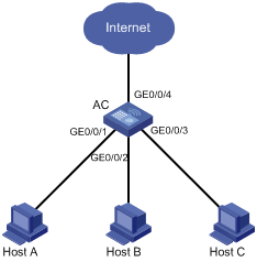
l Users Host A, Host B, and Host C are connected to GigabitEthernet 0/0/1, GigabitEthernet 0/0/2, and GigabitEthernet 0/0/3 of AC.
l AC is connected to an external network through GigabitEthernet 0/0/4.
l GigabitEthernet 0/0/1, GigabitEthernet 0/0/2, GigabitEthernet 0/0/3, and GigabitEthernet 0/0/4 belong to the same VLAN. It is desired that Host A, Host B, and Host C cannot communicate with each other at Layer 2/Layer 3, but can access the external network.
Networking diagram
Figure 2-1 Network diagram for port isolation configuration
Configuration procedure
# Add ports GigabitEthernet 0/0/1, GigabitEthernet 0/0/2 and GigabitEthernet 0/0/3 to the isolation group.
<AC> system-view
[AC] interface GigabitEthernet0/0/1
[AC-GigabitEthernet0/0/1] port-isolate enable
[AC-GigabitEthernet0/0/1] quit
[AC] interface GigabitEthernet0/0/2
[AC-GigabitEthernet0/0/2] port-isolate enable
[AC-GigabitEthernet0/0/2] quit
[AC] interface GigabitEthernet0/0/3
[AC-GigabitEthernet0/0/3] port-isolate enable
[AC-GigabitEthernet0/0/3] return
# Display the information about the isolation group.
<AC> display port-isolate group
Port-isolate group information:
Uplink port support: No
Group ID: 1
GigabitEthernet0/0/1 GigabitEthernet0/0/2 GigabitEthernet0/0/3