- Table of Contents
- Related Documents
-
| Title | Size | Download |
|---|---|---|
| 04-OSPF Troubleshooting Guide | 209.75 KB |
Troubleshooting Layer 3 IP routing issues
OSPF issues
OSPF neighbor down
Symptom
· OSPF neighbor down
· OSPF neighbor flapping occurs.
Common causes
The following are the common causes of this type of issue:
· The BFD session is down, which indicates that BFD has detected a link failure.
· The remote device failed.
· The CPU usage is too high.
· Link failures occurred.
· The OSPF interface is not up.
· The IP addresses of the two ends are not on the same network segment.
· The OSPF settings of the two ends do not match.
¡ A Router ID conflict exists.
¡ The two ends are configured with different area types.
¡ The two ends are configured with different OSPF authentication modes.
¡ The neighboring OSPF interfaces use different timer settings.
¡ The neighboring OSPF interfaces are configured with different network types.
Troubleshooting flow
Figure 1 shows the troubleshooting flowchart.
Figure 1 Troubleshooting flowchart

Solution
1. Identify the reason for the OSPF neighbor down issue through the CLI.
Execute the display ospf event-log peer command. The Reason field in the command output displays the reason for the neighbor state change. Common options include:
¡ DeadExpired
The device had not received any Hello packet before the dead timer expired, and the OSPF neighbor state became Down. In this case, proceed to step 2.
¡ BFDDown
The OSPF neighbor state became Down, because the BFD session went down. In this case, proceed to step 2.
¡ IntVliChange or Virtual link was deleted or the route it relies on was deleted
The neighbor relationship became Down, because the virtual link or its dependency route was deleted. In this case, proceed to step 2.
¡ 1-Way
The OSPF state of the local device became Init, because the OSPF state of the remote device became Down and sent a 1-way Hello packet to the local device. In this case, perform troubleshooting on the remote device.
¡ IntPhyChange
The neighbor relationship became Down, because a related interface went down or its MTU changed. In this case, execute the display interface [ interface-type [ interface-number | interface-number.subnumber ] ] command to view the running state and related information about the interface, and then troubleshoot the interface faults. For other situations, proceed to 11.
2. Check for link failures.
Execute the ping command to check for link failures. If the related links operate correctly, proceed to 3.
3. Identify whether the CPU usage is too high.
Execute the display cpu-usage command to examine CPU usage. If the CPU usage of the device's MPU and interface modules is excessively high, OSPF might fail to receive or send protocol packets correctly, causing neighbor flapping. To resolve this issue, disable unnecessary functions. If the CPU usage is not high, proceed to step 5.
4. Identify whether the memory usage exceeds the memory usage threshold.
Execute the display memory-threshold command. If the Current free-memory state field in the output, which represents the current memory usage of the system, displays Minor, Severe, or Critical, it indicates that the remaining free memory is relatively insufficient. In this case, the device might be unable to send or receive OSPF packets, or might process OSPF packets slowly. To resolve this issue, disable unnecessary functions. If the Current free-memory state field displays Normal, proceed to step 5.
5. Identify whether the physical link state of each OSPF interface is in UP.
Execute the display interface [ interface-type [ interface-number | interface-number.subnumber ] ] command to identify whether the physical link state of each OSPF interface is UP.
¡ If the physical link state of an OSPF interface is DOWN, the interface has failed. First resolve this issue.
¡ If the physical link state of each OSPF interface is UP, execute the display ospf interface command to identify whether each OSPF interface is in a normal state.
- If an OSPF interface is in DOWN state, identify whether the network command was executed in the related OSPF process to advertise the network segment to which that interface belongs. If OSPF did not advertise the network segment, identify whether OSPF is enabled on the interface. If OSPF is enabled, troubleshoot the interface issue on the network layer.
- If the OSPF interfaces are in a normal state, including DR, BDR, DROther, and P-2-P, proceed to step 6.
6. Identify whether the IP addresses of the two ends are in the same network segment.
Execute the display interface brief command to view IP addresses of the two neighboring interfaces.
¡ If the two interface IP addresses are not in the same network segment, execute the ip address command on either of the interfaces to change its IP address. Make sure IP addresses of the two neighboring interfaces are in the same network segment.
¡ If the two interface IP addresses are in the same network segment, proceed to step 7.
7. Identify whether the related OSPF interfaces have the same MTU value.
If the ospf mtu-enable command was executed on the OSPF interfaces, those OSPF interfaces must add the same MTU value to DD packets. If this requirement is not met, the OSPF interfaces cannot be establish an OSPF neighbor relationship. By default, the MTU value in DD packets is 0. Execute the display interface [ interface-type [ interface-number | interface-number.subnumber ] ] command to view the MTU information of each interface.
¡ If the interfaces have different MTU values, execute the mtu size command in interface view to configure the same MTU value for the interfaces.
¡ If the interfaces have the same MTU value, proceed to step 8.
8. Verify that the DR priority of each neighboring OSPF interface is not zero.
On a broadcast or NBMA network, to elect a DR correctly, make sure that a minimum of one OSPF interface has a non-zero DR priority. If the DR priority is 0 for both of the two neighboring OSPF interfaces, the highest neighbor states at both ends are 2-Way. Execute the display ospf interface command to view OSPF interface information. The Priority field in the command output displays the DR priority of an interface.
If the DR priority of each neighboring interface is not zero, proceed to step 9.
9. Identify whether an NBMA or P2MP unicast neighbor has been manually specified.
When the network type of an OSPF interface is NBMA or P2MP unicast, you must use the peer command to specify a neighbor by its IP address. Execute the display this command in interface view. If the network type of an interface is NBMA or P2MP unicast, execute the peer command to manually specify a neighbor by its IP address.
If an NBMA or P2MP unicast neighbor has been manually specified, proceed to step 10.
10. Identify whether the OSPF settings at the two ends are correct.
a. Execute the display ospf command to view the OSPF router IDs of the two ends. If the two ends use the same router ID, edit the configuration to avoid the conflict. If the two ends use different router IDs, proceed to the next step.
b. Execute the display ospf interface command to view the OSPF area IDs of the two ends. If the two ends use different area IDs, edit the configuration to ensure area ID consistency. If the two ends use the same area ID, proceed to the next step.
c. Execute the display ospf interface command to view the network types of interfaces at the two ends. If the two interfaces are configured with different network types, edit the configuration to ensure network type consistency. If the network type is PTP for one end and Broadcast for the other, the neighbor relationship can reach Full state, but routing information cannot be calculated.
If the two ends are configured with the same network type, proceed to the next step.
d. Execute the display ospf statistics error command every 10 seconds for 5 minutes to view OSPF error statistics. Pay attention to the following fields:
- Bad authentication type: If the value of this field keeps increasing, the two OSPF neighbors are configured with different OSPF authentication modes. To resolve this issue, edit the authentication mode setting to make sure the two devices have the same authentication mode.
- Hello-time mismatch: If the value of this field keeps increasing, the two neighboring interfaces are configured with different hello intervals. To resolve this issue, edit the hello interval setting to make sure the OSPF interfaces have the same hello interval value.
- Dead-time mismatch: If the value of this field keeps increasing, the two neighboring interfaces are configured with different dead intervals. To resolve this issue, edit the dead interval setting to make sure the OSPF interfaces have the same dead interval value.
- Ebit option mismatch: If the value of this field keeps increasing, the two neighbors are of different OSPF area types. (For example, one end is in a normal area and the other end is in a stub area.) To resolve this issue, edit the OSPF area setting to make sure the two ends have the same area type.
If the issue persists, proceed to step 11.
11. If the issue persists, collect the following information and contact Technical Support:
¡ Results of each step.
¡ The configuration file, log messages, and alarm messages.
Related alarm and log messages
Alarm messages
Module name: OSPF-TRAP-MIB
· ospfVirtIfStateChange (1.3.6.1.2.1.14.16.2.1)
· ospfNbrStateChange (1.3.6.1.2.1.14.16.2.2)
· ospfVirtNbrStateChange (1.3.6.1.2.1.14.16.2.3)
Log messages
· OSPF/5/OSPF_NBR_CHG
· OSPF/5/OSPF_NBR_CHG_REASON
OSPF neighbor unable to enter Full state
Symptom
The OSPF neighbor state machine involves neighbor states of Down, Init, 2-way, ExStart, Exchange, Loading, and Full. Among them, the stable states are Down, 2-way, and Full.
· Down—OSPF is not enabled.
· 2-way—The neighbor relationship between DR Others.
· Full—The local device and the neighbor are fully adjacent.
In networks using OSPF for route calculation and forwarding, only 2-way and Full are normal neighbor states. If the neighbor state is neither 2-way nor Full, it indicates an abnormal neighbor relationship.
Common causes
The following are the common causes of this type of issue:
· OSPF packets were dropped due to link failures.
· The DR priority of the neighboring interfaces is not appropriate.
· The two ends use different MTU values.
Troubleshooting flow
Figure 2 shows the troubleshooting flowchart:
Figure 2 Troubleshooting flowchart
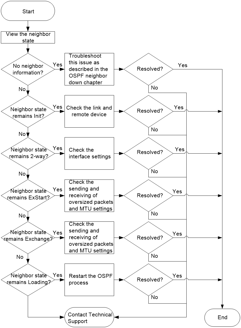
Solution
1. Execute the display ospf peer command to view OSPF neighbor information, and perform different tasks based on the neighbor state.
¡ If no neighbor information exists:
The OSPF neighbor went down or flapped. See "OSPF neighbor down" to troubleshoot the issue.
¡ If the neighbor state remains Init:
The remote device cannot receive Hello packets from the local device. In this case, identify whether the link or the remote device has failed.
¡ If the neighbor state remains 2-Way:
Execute the display ospf interface verbose command to identify whether the DR priority of the neighbor-facing OSPF interface is zero.
- If the DR priority of the OSPF interface is zero, no action is required.
- If the DR priority of the OSPF interface is not zero, proceed to step 2.
¡ If the neighbor state remains ExStart:
The device keeps performing DD negotiation but cannot perform DD synchronization. The following are the common causes for this issue:
- The neighbor-facing interface cannot send and receive oversized packets correctly.
Repeat the ping -s packet-size neighbor-address command, set the value for the packet-size argument to 1500 or greater, and then view the transmission and reception of oversized packets. If the remote end still cannot be pinged, troubleshoot the link issue first.
- The two ends use different MTU values.
If the ospf mtu-enable command was configured on the neighbor-facing OSPF interface, identify whether the two ends use the same MTU value. If they use different MTU values, configure the same MTU value for them.
If the issue persists, proceed to step 2.
¡ If the neighbor state remains Exchange:
The device is performing DD packet exchange. Troubleshoot this issue in the same way as when the neighbor state remains ExStart.
If the issue persists, proceed to step 2.
¡ If the neighbor state remains Loading:
Execute the reset ospf [ process-id ] process command to restart the OSPF process.
If the issue persists, proceed to step 2.
2. If the issue persists, collect the following information and contact Technical Support:
¡ Results of each step.
¡ The configuration file, log messages, and alarm messages.
Related alarm and log messages
Alarm messages
N/A
Log messages
N/A
OSPF device unable to learn partial OSPF routes
Symptom
An OSPF device fails to learn partial OSPF routes.
Common causes
The following are the common causes of this type of issue:
· The network type is P2P for one end and is Broadcast for the other end. Although the neighbor relationship is in Full state, the two ends cannot learn routes from each other.
· The OSPF process is configured with the filter-policy import command.
· The filter import command is configured in the local OSPF area.
· The filter export command is configured in other OSPF areas.
· The OSPF process is bound to a VPN instance. The tag of routes redistributed to the OSPF process is the same as that in the AS External LSA (Type-5 LSA) or NSSA External LSA (Type-7 LSA).
· The ABR is unreachable.
· The ABR does not take the Summary LSAs from non-backbone areas into account during route calculation.
· The ASBR is unreachable.
· In the AS External LSA or NSSA External LSA, the FA address is unreachable.
· The route to the FA address in the NSSA External LSA is not in the same area as the NSSA External LSA.
Troubleshooting flow
Figure 3 and Figure 4 show the troubleshooting flowcharts.
Figure 3 Troubleshooting flowchart 1
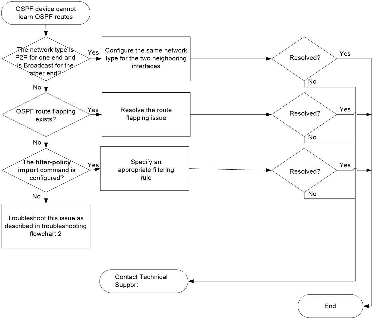
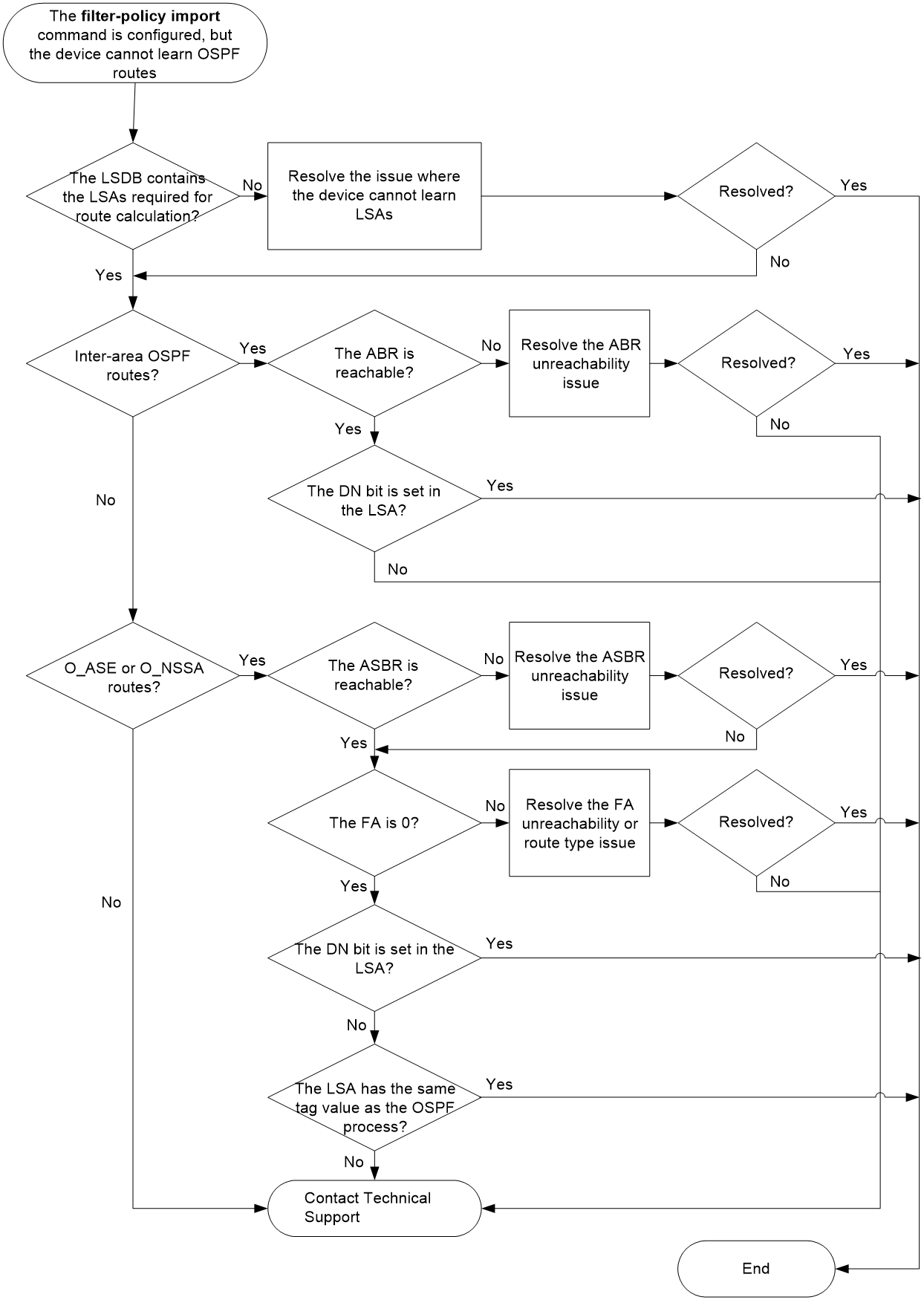
Figure 4 Troubleshooting flowchart 2
Solution
1. Identify whether the network type is P2P for one end and is Broadcast for the other end.
If yes, the neighbor relationship can reach Full state, but the two ends cannot learn routes from each other. To resolve this issue:
a. Execute the display ospf interface command to view the network types of the two neighboring OSPF interfaces.
<Sysname> display ospf interface
OSPF Process 1 with Router ID 5.5.5.5
Interfaces
Area: 0.0.0.1
IP Address Type State Cost Pri DR BDR
192.168.51.5 PTP P-2-P 1 1 0.0.0.0 0.0.0.0
b. If this issue exists, execute the ospf network-type command to configure the same network type for the two neighboring interfaces.
If this issue does not exist, proceed to step 2.
2. Check the OSPF routing table multiple times for OSPF route flapping.
Execute the display ip routing-table protocol ospf verbose command, and then identify flapping OSPF routes by the Age field in the command output.
¡ If the Age field of an OSPF route displays a small value, the OSPF route flaps, and you must troubleshoot the route flapping issue.
¡ If no route flapping issue is found, proceed to step 3.
<Sysname> display ip routing-table protocol ospf verbose
Summary count : 3
Destination: 192.168.12.0/24
Protocol: O_INTER
Process ID: 1
SubProtID: 0x2 Age: 12h53m09s
Cost: 2 Preference: 10
IpPre: N/A QosLocalID: N/A
Tag: 0 State: Active Adv
OrigTblID: 0x0 OrigVrf: default-vrf
TableID: 0x2 OrigAs: 0
NibID: 0x13000003 LastAs: 0
AttrID: 0xffffffff Neighbor: 0.0.0.0
Flags: 0x10041 OrigNextHop: 192.168.51.1
Label: NULL RealNextHop: 192.168.51.1
BkLabel: NULL BkNextHop: N/A
SRLabel: NULL Interface: GigabitEthernet0/0/2
BkSRLabel: NULL BkInterface: N/A
SIDIndex: NULL InLabel: NULL
Tunnel ID: Invalid IPInterface: GigabitEthernet0/0/2
BkTunnel ID: Invalid BkIPInterface: N/A
FtnIndex: 0x0 ColorInterface: N/A
TrafficIndex: N/A BkColorInterface: N/A
Connector: 0.0.0.0 VpnPeerId: N/A
Dscp: N/A Exp: N/A
SRTunnelID: Invalid StatFlags: 0x0
SID Type: N/A SID: N/A
BkSID: N/A NID: Invalid
FlushNID: Invalid BkNID: Invalid
BkFlushNID: Invalid PathID: 0x0
CommBlockLen: 0
OrigLinkID: 0x0 RealLinkID: 0x0
Destination: 192.168.24.0/24
Protocol: O_INTER
Process ID: 1
SubProtID: 0x2 Age: 12h53m09s
Cost: 3 Preference: 10
IpPre: N/A QosLocalID: N/A
Tag: 0 State: Active Adv
OrigTblID: 0x0 OrigVrf: default-vrf
TableID: 0x2 OrigAs: 0
NibID: 0x13000003 LastAs: 0
AttrID: 0xffffffff Neighbor: 0.0.0.0
Flags: 0x10041 OrigNextHop: 192.168.51.1
Label: NULL RealNextHop: 192.168.51.1
BkLabel: NULL BkNextHop: N/A
SRLabel: NULL Interface: GigabitEthernet0/0/2
BkSRLabel: NULL BkInterface: N/A
SIDIndex: NULL InLabel: NULL
Tunnel ID: Invalid IPInterface: GigabitEthernet0/0/2
BkTunnel ID: Invalid BkIPInterface: N/A
FtnIndex: 0x0 ColorInterface: N/A
TrafficIndex: N/A BkColorInterface: N/A
Connector: 0.0.0.0 VpnPeerId: N/A
Dscp: N/A Exp: N/A
SRTunnelID: Invalid StatFlags: 0x0
SID Type: N/A SID: N/A
BkSID: N/A NID: Invalid
FlushNID: Invalid BkNID: Invalid
BkFlushNID: Invalid PathID: 0x0
CommBlockLen: 0
OrigLinkID: 0x0 RealLinkID: 0x0
Destination: 192.168.51.0/24
Protocol: O_INTRA
Process ID: 1
SubProtID: 0x1 Age: 12h54m07s
Cost: 1 Preference: 10
IpPre: N/A QosLocalID: N/A
Tag: 0 State: Inactive Adv
OrigTblID: 0x0 OrigVrf: default-vrf
TableID: 0x2 OrigAs: 0
NibID: 0x13000001 LastAs: 0
AttrID: 0xffffffff Neighbor: 0.0.0.0
Flags: 0x10c1 OrigNextHop: 0.0.0.0
Label: NULL RealNextHop: 0.0.0.0
BkLabel: NULL BkNextHop: N/A
SRLabel: NULL Interface: GigabitEthernet0/0/2
BkSRLabel: NULL BkInterface: N/A
SIDIndex: NULL InLabel: NULL
Tunnel ID: Invalid IPInterface: GigabitEthernet0/0/2
BkTunnel ID: Invalid BkIPInterface: N/A
FtnIndex: 0x0 ColorInterface: N/A
TrafficIndex: N/A BkColorInterface: N/A
Connector: 0.0.0.0 VpnPeerId: N/A
Dscp: N/A Exp: N/A
SRTunnelID: Invalid StatFlags: 0x0
SID Type: N/A SID: N/A
BkSID: N/A NID: Invalid
FlushNID: Invalid BkNID: Invalid
BkFlushNID: Invalid PathID: 0x0
CommBlockLen: 0
OrigLinkID: 0x0 RealLinkID: 0x0
3. Identify whether the filter-policy import command is configured in the OSPF process.
In scenarios where route filtering is configured, check for OSPF route filtering errors.
a. Execute the display this command in the related OSPF process on the local device to identify whether the filter-policy import command is configured in the OSPF process.
[Sysname-ospf-1] display this
#
ospf 1
import-route direct
filter-policy 2000 import
area 0.0.0.1
network 192.168.51.0 0.0.0.255
nssa
#
return
b. If the filter-policy import command is configured, identify whether the filtering rule specified by using this command are appropriate.
- If an ACL is used for route filtering, execute the display acl { acl-number | name acl-name } command to view its configuration details.
- If a prefix list is used for route filtering, execute the display ip prefix-list command to view its configuration details.
- If a routing policy is used for route filtering, execute the display route-policy command to view its configuration details.
If the desired routes are unexpectedly denied by the filtering rule, identify whether the filtering rule meets the requirements. If it is inappropriate, specify a new filtering rule by using the filter-policy import command.
c. If the desired routes are not denied by the filtering rule or the filter-policy import command is not configured in the OSPF process, proceed to step 4.
Choose the appropriate troubleshooting method based on the type of OSPF routes that have not been learned in the OSPF process.
If the OSPF process lacks intra-area routes, execute the display ospf [ process-id ] lsdb router command in user view to identify whether the LSDB of the OSPF process contains all the Router LSAs in the area.
<Sysname> display ospf 100 lsdb router
OSPF Process 100 with Router ID 5.5.5.5
Area: 0.0.0.1
Link State Database
Type : Router
LS ID : 5.5.5.5
Adv Rtr : 5.5.5.5
LS age : 7
Len : 36
Options : ASBR O NP
Seq# : 80000026
Checksum : 0x5f1f
Link Count: 1
Link ID: 192.168.51.1
Data : 192.168.51.5
Link Type: TransNet
Metric : 1
Type : Router
LS ID : 1.1.1.1
Adv Rtr : 1.1.1.1
LS age : 8
Len : 36
Options : ASBR ABR O NP
Seq# : 8000002a
Checksum : 0x534a
Link Count: 1
Link ID: 192.168.51.1
Data : 192.168.51.1
Link Type: TransNet
Metric : 1
- If the LSDB lacks some Router LSAs, proceed to step 7.
- If the LSDB contains all of the Router LSAs, but cannot calculate routing information, proceed to step 7.
¡ Inter-area OSPF routes
If the OSPF process lacks inter-area routes, execute the display ospf [ process-id ] lsdb summary command in user view to identify whether the LSDB of the OSPF process contains all the Network Summary LSAs from other areas.
<Sysname> display ospf lsdb summary
OSPF Process 1 with Router ID 5.5.5.5
Area: 0.0.0.1
Link State Database
Type : Sum-Net
LS ID : 192.168.24.0
Adv Rtr : 1.1.1.1
LS age : 576
Len : 28
Options : O NP
Seq# : 8000001f
Checksum : 0x4c25
Net Mask : 255.255.255.0
Tos 0 Metric: 2
Type : Sum-Net
LS ID : 192.168.12.0
Adv Rtr : 1.1.1.1
LS age : 576
Len : 28
Options : O NP
Seq# : 8000001f
Checksum : 0xc6b7
Net Mask : 255.255.255.0
Tos 0 Metric: 1
- If the LSDB lacks a Network Summary LSA, identify whether the filter import command is configured in the local OSPF area or the filter export command is configured in the OSPF area from which the missing Network Summary LSA was advertised. If the Network Summary LSA was unexpectedly filtered out by the filtering rule specified by using the filter import or filter export command, adjust filtering rule to avoid this issue.
You can use the filter import and filter export commands to specify ACLs, prefix lists, or routing policies for route filtering. To view the configuration details of an ACL, prefix list, or routing policy, execute one of the display acl { acl-number | name acl-name }, display ip prefix-list, or display route-policy command as needed.
- If the LSDB contains all of the Network Summary LSAs, but cannot calculate routing information, proceed to step 7.
¡ O_ASE or O_NSSA routes
If the OSPF process lacks O_ASE routes, execute the display ospf [ process-id ] lsdb ase command in user view to identify whether the LSDB of the OSPF process contains AS External LSAs.
<Sysname> display ospf 100 lsdb ase
OSPF Process 100 with Router ID 1.1.1.1
Link State Database
Type : External
LS ID : 10.1.1.0
Adv Rtr : 1.1.1.1
LS age : 713
Len : 36
Options : O E
Seq# : 80000001
Checksum : 0x934b
Net Mask : 255.255.255.0
TOS 0 Metric: 1
E Type : 2
Forwarding Address : 192.168.51.5
Tag : 1
If the OSPF process lacks O_NSSA routes, execute the display ospf [ process-id ] lsdb nssa command in user view to identify whether the LSDB of the OSPF process contains NSSA External LSAs.
<Sysname> display ospf 100 lsdb nssa
OSPF Process 100 with Router ID 1.1.1.1
Area: 0.0.0.0
Link State Database
Area: 0.0.0.1
Link State Database
Type : NSSA
LS ID : 192.168.51.0
Adv Rtr : 5.5.5.5
LS age : 965
Len : 36
Options : O NP
Seq# : 8000001f
Checksum : 0x1dfa
Net Mask : 255.255.255.0
TOS 0 Metric: 1
E Type : 2
Forwarding Address : 192.168.51.5
Tag : 1
Type : NSSA
LS ID : 10.1.1.0
Adv Rtr : 5.5.5.5
LS age : 965
Len : 36
Options : O NP
Seq# : 8000001f
Checksum : 0x6840
Net Mask : 255.255.255.0
TOS 0 Metric: 1
E Type : 2
Forwarding Address : 192.168.51.5
Tag : 1
- If the LSDB lacks some AS External LSAs or NSSA External LSAs, proceed to step 7.
- If the LSDB contains all of the AS External LSAs or NSSA External LSAs, but cannot learn O_ASE or O_NSSA routes, proceed to step 7.
5. Identify whether the ABR is reachable.
Inter-area routes are advertised by the ABR. If the local device and the ABR cannot reach each other, the local device will not be able to learn inter-area routes.
a. Execute the display ospf [ process-id ] lsdb summary command on the local device, and then view the Adv Rtr field in the command output. This field displays the router ID of the ABR, which advertised the Network Summary LSA.
<Sysname> display ospf 100 lsdb summary
OSPF Process 100 with Router ID 5.5.5.5
Area: 0.0.0.1
Link State Database
Type : Sum-Net
LS ID : 192.168.12.0
Adv Rtr : 1.1.1.1
LS age : 913
Len : 28
Options : O E
Seq# : 80000001
Checksum : 0x5d45
Net Mask : 255.255.255.0
Tos 0 Metric: 1
b. Execute the display ospf abr-asbr command on the local device, and then view the Destination and RtType fields in the command output. If the RtType field displays ABR, the Destination field displays the router ID of the ABR. In this situation, the local device has a route to the ABR.
<Sysname> display ospf 100 abr-asbr
OSPF Process 100 with Router ID 5.5.5.5
Routing Table to ABR and ASBR
Type Destination Area Cost Nexthop RtType
Intra 1.1.1.1 0.0.0.1 1 192.168.51.1 ABR
c. If the output of the display ospf abr-asbr command does not include a route to the ABR, proceed to step 7.
d. If the output of the display ospf abr-asbr command includes a route to the ABR, and the local device is an ABR, identify whether the local OSPF area is a backbone area.
- If the OSPF area is not a backbone area (with a non-zero area ID), no action is required. According to RFC 2328, ABRs do not process the Network Summary LSAs received from non-backbone areas.
- If the OSPF area is a backbone area (with an area ID of 0), but it cannot learn inter-area routes, proceed to step 7.
e. If the output of the display ospf abr-asbr command includes a route to the ABR, and the OSPF process is bound to a VPN instance, identify whether the vpn-instance-capability simple command is configured in the OSPF process. If this command is configured, proceed to step 7.
If this command is not configured, troubleshoot this issue as described in Table 1.
Table 1 Troubleshooting methods
|
Whether the DN bit is set to 1 |
Troubleshooting method |
|
The vpn-instance-capability simple command is not configured, and the Option field of the related Network Summary LSA contains the DN bit (the DN bit is set). |
According to RFC 2328, private OSPF processes do not use Network Summary LSAs that contain the DN bit for route calculation. It is normal that the local device cannot learn inter-area routes. |
|
The vpn-instance-capability simple command is not configured, and the Option field of the related Network Summary LSA does not contain the DN bit. |
Proceed to step 7. |
6. Identify whether the ASBR is reachable and whether loop prevention is enabled.
O_ASE routes and O_NSSA routes are advertised by the ASBR. If the local device and the ASBR cannot reach each other, the local device will not be able to learn routes from devices located in other ASs.
a. Execute the display ospf [ process-id ] lsdb [ ase | nssa ] command, and then view the Adv Rtr field in the command output. This field displays the router ID of the ASBR, which advertised the AS External LSA (Type-5) or NSSA External LSA (Type-7).
<Sysname> display ospf 100 lsdb ase
OSPF Process 100 with Router ID 1.1.1.1
Link State Database
Type : External
LS ID : 10.1.1.0
Adv Rtr : 1.1.1.1
LS age : 169
Len : 36
Options : O E
Seq# : 80000001
Checksum : 0x934b
Net Mask : 255.255.255.0
TOS 0 Metric: 1
E Type : 2
Forwarding Address : 192.168.51.5
Tag : 1
<Sysname> display ospf 100 lsdb nssa
OSPF Process 100 with Router ID 1.1.1.1
Area: 0.0.0.0
Link State Database
Area: 0.0.0.1
Link State Database
Type : NSSA
LS ID : 192.168.51.0
Adv Rtr : 5.5.5.5
LS age : 156
Len : 36
Options : O NP
Seq# : 80000001
Checksum : 0x59dc
Net Mask : 255.255.255.0
TOS 0 Metric: 1
E Type : 2
Forwarding Address : 192.168.51.5
Tag : 1
Type : NSSA
LS ID : 10.1.1.0
Adv Rtr : 5.5.5.5
LS age : 156
Len : 36
Options : O NP
Seq# : 80000001
Checksum : 0xa422
Net Mask : 255.255.255.0
TOS 0 Metric: 1
E Type : 2
Forwarding Address : 192.168.51.5
Tag : 1
b. Execute the display ospf abr-asbr command, and then view the Destination and RtType fields in the command output. If the RtType field displays ASBR, the Destination field displays the router ID of the ASBR. In this situation, the local device has a route to the ASBR.
<Sysname> display ospf 100 abr-asbr
OSPF Process 100 with Router ID 1.1.1.1
Routing Table to ABR and ASBR
Type Destination Area Cost Nexthop RtType
Intra 5.5.5.5 0.0.0.1 1 192.168.51.5 ASBR
c. If the output of the display ospf abr-asbr command does not include a route to the ASBR, proceed to step 7.
d. If the output of the display ospf abr-asbr command includes a route to the ASBR, and the Forwarding Address field of the LSA is not 0, check the reachability and route type of the forwarding address.
Execute the disply ospf routing forwarding-address { mask-length | mask } command in user view to identify whether the local device has a route to the forwarding address.
<Sysname> display ospf 100 routing 192.168.51.5 24
OSPF Process 100 with Router ID 1.1.1.1
Routing Table
Routing for network
Destination Cost Type NextHop AdvRouter Area
192.168.51.0/24 1 Transit 0.0.0.0 5.5.5.5 0.0.0.1
Total nets: 1
Intra area: 1 Inter area: 0 ASE: 0 NSSA: 0
Troubleshoot this issue as described in Table 2.
Table 2 Troubleshooting methods
|
Whether the forwarding address is reachable |
Troubleshooting method |
|
Unreachable |
If the display ospf routing forwarding-address { mask-length | mask } command does not display route information for the forwarding address, the forwarding address is unreachable. In this case, proceed to step 7. |
|
Reachable |
If the missing external routes are advertised in an NSSA External LSA, no action is required. According to RFC 3101, the route to the forwarding address must belong to the same OSPF area as the NSSA External LSA. If the Area field displays an area ID different from that of an NSSA External LSA, the OSPF process will not use that NSSA External LSA for route calculation. Therefore, it is normal that the OSPF process lacks the related external routes. |
|
If the Type field displays Type1 or Type2 in the output of the display ospf routing forwarding-address { mask-length | mask } command, the route to the forwarding address is an external route. According to RFC 2328, if the route to a non-zero forwarding address is an external route, OSPF will not use the related LSA for route calculation. Therefore, it is normal that the OSPF process lacks the related external routes. |
e. If the output of the display ospf abr-asbr command includes a route to the ASBR, and the OSPF process is bound to a VPN instance, identify whether the vpn-instance-capability simple command is configured in the OSPF process.
If this command is configured, proceed to step 7.
If this command is not configured, troubleshoot this issue as described in Table 3.
Table 3 Troubleshooting methods
|
Whether the DN bit is set to 1 |
Troubleshooting method |
|
The vpn-instance-capability simple command is not configured, and the Option field of the related AS External LSA or NSSA External LSA contains the DN bit. |
According to RFC 2328, private OSPF processes do not use AS External LSAs or NSSA External LSAs that contain the DN bit for route calculation. It is normal that the local device cannot learn the related external routes. |
|
The vpn-instance-capability simple command is not configured, and the Option field of the related AS External LSA or NSSA External LSA does not contain the DN bit. |
Execute the display ospf command, and then view the Default ASE parameters field in the command output to identify whether the AS External LSA or NSSA External LSA has the same tag value as the private OSPF process: · If they use the same tag value, no action is required. According to RFC 2328, private OSPF processes do not use such LSAs for route calculation. Therefore, it is normal that the OSPF process does not have the related external routes. · If they use different tag values, proceed to step 7. |
7. If the issue persists, collect the following information and contact Technical Support:
¡ Results of each step.
¡ The configuration file, log messages, and alarm messages.
Related alarm and log messages
Alarm messages
N/A
Log messages
N/A
Route flapping caused by an IP address conflict
Symptom
In an OSPF network, if different devices use the same interface IP address, OSPF route flapping will occur. When this issue occurs, the related devices typically have the following phenomena:
· The display cpu-usage command displays a high CPU usage.
· OSPF marks LSAs as stale frequently, and re-generates LSAs.
· The device refreshes routes frequently, and route calculations are incorrect.
Solution
In this troubleshooting example, the network diagram is as shown in Figure 5. The troubleshooting methods for other networks are similar as that for this network.

2. On each device in the OSPF network, execute the display ospf [ process-id ] lsdb command every second to view their OSPF LSDB information.
3. Check for abnormal LSA aging.
If abnormal LSA aging exists, you can find the following symptoms:
¡ On Device A, the Age field of a Network LSA (Type-2) remains at the minimum value, but its Sequence field increases rapidly. For example, in the following command output, the Age of Network LSA 172.168.0.1 (LinkStateID) does not naturally increase, and the Sequence field grows from 8000002D to 8000002F in a short time.
<Sysname> display ospf 100 lsdb
OSPF Process 100 with Router ID 10.1.1.1
Link State Database
Area: 0.0.0.0
Type LinkState ID AdvRouter Age Len Sequence Metric
Router 3.3.3.3 3.3.3.3 797 48 80000009 0
Router 1.1.1.1 1.1.1.1 835 36 80000005 0
Router 4.4.4.4 4.4.4.4 798 36 80000004 0
Router 10.1.1.1 10.1.1.1 415 36 80000007 0
Router 2.2.2.2 2.2.2.2 415 48 80000015 0
Network 192.168.0.2 3.3.3.3 802 32 80000002 0
Network 172.168.0.3 4.4.4.4 791 32 80000002 0
Network 172.168.0.1 10.1.1.1 7 32 8000002D 0
<Sysname> display ospf 100 lsdb
OSPF Process 100 with Router ID 10.1.1.1
Link State Database
Area: 0.0.0.0
Type LinkState ID AdvRouter Age Len Sequence Metric
Router 3.3.3.3 3.3.3.3 810 48 80000009 0
Router 1.1.1.1 1.1.1.1 848 36 80000005 0
Router 4.4.4.4 4.4.4.4 811 36 80000004 0
Router 10.1.1.1 10.1.1.1 428 36 80000007 0
Router 2.2.2.2 2.2.2.2 428 48 80000015 0
Network 192.168.0.2 3.3.3.3 815 32 80000002 0
Network 172.168.0.3 4.4.4.4 804 32 80000002 0
Network 172.168.0.1 10.1.1.1 4 32 8000002F 0
¡ On Device B, the Age field of the same Network LSA frequently switches between 3600 and other smaller values, and its Sequence field increases rapidly. For example, in the following command output, the Age of Network LSA 172.168.0.1 (LinkStateID) frequently switches between 3600 and other smaller values, and the Sequence field grows from 80000023 to 80000041 in a short time.
<Sysname> display ospf 100 lsdb
OSPF Process 100 with Router ID 2.2.2.2
Link State Database
Area: 0.0.0.0
Type LinkState ID AdvRouter Age Len Sequence Metric
Router 3.3.3.3 3.3.3.3 708 48 80000009 0
Router 1.1.1.1 1.1.1.1 746 36 80000005 0
Router 4.4.4.4 4.4.4.4 709 36 80000004 0
Router 10.1.1.1 10.1.1.1 329 36 80000007 0
Router 2.2.2.2 2.2.2.2 327 48 80000015 0
Network 172.168.0.3 4.4.4.4 702 32 80000002 0
Network 192.168.0.2 3.3.3.3 713 32 80000002 0
Network 172.168.0.1 10.1.1.1 3600 32 80000023 0
<Sysname> display ospf 100 lsdb
OSPF Process 100 with Router ID 2.2.2.2
Link State Database
Area: 0.0.0.0
Type LinkState ID AdvRouter Age Len Sequence Metric
Router 3.3.3.3 3.3.3.3 748 48 80000009 0
Router 1.1.1.1 1.1.1.1 786 36 80000005 0
Router 4.4.4.4 4.4.4.4 749 36 80000004 0
Router 10.1.1.1 10.1.1.1 369 36 80000007 0
Router 2.2.2.2 2.2.2.2 367 48 80000015 0
Network 172.168.0.3 4.4.4.4 742 32 80000002 0
Network 192.168.0.2 3.3.3.3 753 32 80000002 0
Network 172.168.0.1 10.1.1.1 7 32 80000041 0
¡ On Device C, the Age field of the same Network LSA remains at 3600 or the Network LSA occasionally disappears, and the Sequence field increases rapidly. For example, in the following command output, the Age of Network LSA 172.168.0.1 (LinkStateID) remains at 3600 or the Network LSA occasionally disappears. When the Network LSA exists, its Sequence field grows from 80000309 to 80000346 in a short time.
<Sysname> display ospf 100 lsdb
OSPF Process 100 with Router ID 3.3.3.3
Link State Database
Area: 0.0.0.0
Type LinkState ID AdvRouter Age Len Sequence Metric
Router 3.3.3.3 3.3.3.3 740 48 8000000D 0
Router 4.4.4.4 4.4.4.4 759 36 80000008 0
Router 10.1.1.1 10.1.1.1 364 36 8000000B 0
Router 2.2.2.2 2.2.2.2 366 48 80000019 0
Network 172.168.0.3 4.4.4.4 755 32 80000006 0
Network 192.168.0.2 3.3.3.3 744 32 80000006 0
Network 172.168.0.1 10.1.1.1 3600 32 80000309 0
<Sysname> display ospf 100 lsdb
OSPF Process 100 with Router ID 3.3.3.3
Link State Database
Area: 0.0.0.0
Type LinkState ID AdvRouter Age Len Sequence Metric
Router 3.3.3.3 3.3.3.3 745 48 8000000D 0
Router 4.4.4.4 4.4.4.4 764 36 80000008 0
Router 10.1.1.1 10.1.1.1 369 36 8000000B 0
Router 2.2.2.2 2.2.2.2 371 48 80000019 0
Network 172.168.0.3 4.4.4.4 760 32 80000006 0
Network 192.168.0.2 3.3.3.3 749 32 80000006 0
<Sysname> display ospf 100 lsdb
OSPF Process 100 with Router ID 3.3.3.3
Link State Database
Area: 0.0.0.0
Type LinkState ID AdvRouter Age Len Sequence Metric
Router 3.3.3.3 3.3.3.3 1302 48 8000000D 0
Router 4.4.4.4 4.4.4.4 1321 36 80000008 0
Router 10.1.1.1 10.1.1.1 926 36 8000000B 0
Router 2.2.2.2 2.2.2.2 928 48 80000019 0
Network 172.168.0.3 4.4.4.4 1317 32 80000006 0
Network 192.168.0.2 3.3.3.3 1306 32 80000006 0
Network 172.168.0.1 10.1.1.1 3600 32 80000346 0
4. Check for OSPF route flapping.
On Device B, execute the display ospf [ process-id ] routing command every second to check for route flapping.
<Sysname> display ospf 100 routing
OSPF Process 100 with Router ID 2.2.2.2
Routing Table
Routing for network
Destination Cost Type NextHop AdvRouter Area
192.168.0.0/24 1 Transit 0.0.0.0 3.3.3.3 0.0.0.0
172.168.0.0/24 1 Transit 0.0.0.0 10.1.1.1 0.0.0.0
Total nets: 2
Intra area: 2 Inter area: 0 ASE: 0 NSSA: 0
<Sysname> display ospf 100 routing
OSPF Process 100 with Router ID 2.2.2.2
Routing Table
Routing for network
Destination Cost Type NextHop AdvRouter Area
192.168.0.0/24 1 Transit 0.0.0.0 3.3.3.3 0.0.0.0
172.168.0.0/24 2 Transit 192.168.0.2 4.4.4.4 0.0.0.0
Total nets: 2
Intra area: 2 Inter area: 0 ASE: 0 NSSA: 0
If OSPF route flapping occurs, and multiple executions of the display ospf peer command show that the neighbor relationship is not flapping, an IP address conflict exists in the OSPF network. Meanwhile, this indicates that one of the conflicting devices is a DR, because Network LSAs (Type-2) are generated by DRs.
If two Network LSAs with the same LinkState ID exist and they are aging abnormally on any device, both of the conflicting devices are DRs.
<Sysname> display ospf 100 lsdb
OSPF Process 100 with Router ID 10.1.1.1
Link State Database
Area: 0.0.0.0
Type LinkState ID AdvRouter Age Len Sequence Metric
Router 3.3.3.3 3.3.3.3 367 48 80000021 0
Router 4.4.4.4 4.4.4.4 369 36 80000013 0
Router 10.1.1.1 10.1.1.1 477 36 80000012 0
Router 2.2.2.2 2.2.2.2 403 48 8000002B 0
Network 192.168.0.1 2.2.2.2 395 32 80000002 0
Network 172.168.0.1 3.3.3.3 3600 32 8000002B 0
Network 172.168.0.1 10.1.1.1 9 32 80000036 0
<Sysname> display ospf 100 lsdb
OSPF Process 100 with Router ID 10.1.1.1
Link State Database
Area: 0.0.0.0
Type LinkState ID AdvRouter Age Len Sequence Metric
Router 3.3.3.3 3.3.3.3 460 48 80000021 0
Router 4.4.4.4 4.4.4.4 462 36 80000013 0
Router 10.1.1.1 10.1.1.1 570 36 80000012 0
Router 2.2.2.2 2.2.2.2 496 48 8000002B 0
Network 192.168.0.1 2.2.2.2 488 32 80000002 0
Network 172.168.0.1 3.3.3.3 3600 32 80000034 0
Network 172.168.0.1 10.1.1.1 6 32 80000041 0
5. Identify the conflicting devices.
You can use the output of the display ospf lsdb command to find the devices causing the IP address conflict.
If only one of the conflicting devices is a DR, perform the following task:
a. Check the AdvRouter field of the abnormal Network LSA to find the router ID of the advertising DR.
b. Check the LinkState ID field of the abnormal Network LSA to identify the interface that uses the conflicting IP address, and then find the IP address of the interface.
c. Based on the obtained interface address and the IP address plan, identify another conflicting device.
In this example, the DR with Router ID 10.1.1.1 has an interface IP address conflict with another device, and the conflicting IP address is 172.168.0.1. Based on the IP address plan, you can find the other device causing the conflict.
If both of the conflicting devices are DRs, perform the following task:
d. Check the AdvRouter field of each abnormal Network LSA to find the router IDs of the advertising DRs.
e. Check the LinkState ID field of each abnormal Network LSA to identify the interfaces causing the IP address conflict.
6. Change the IP address of a conflicting device, according to the network IP address plan.
7. If the issue persists, collect the following information and contact Technical Support:
¡ Results of each step.
¡ The configuration file, log messages, and alarm messages.
Related alarm and log messages
Alarm messages
N/A
Log messages
N/A