- Table of Contents
- Related Documents
-
| Title | Size | Download |
|---|---|---|
| 01-BGP Troubleshooting Guide | 291.15 KB |
Troubleshooting Layer 3 IP routing issues
BGP issues
BGP session unable to enter Established state
Symptom
The session between the local router and a peer or peer group cannot transition to Established state.
Common causes
The following are the common causes of this type of issue:
· BGP packet forwarding is blocked.
· The packets used for establishing or maintaining the BGP TCP connection are filtered out by ACLs.
· A router ID conflict exists between the BGP peers within the autonomous system.
· The specified peer or peer group AS number is incorrect.
· The peer address specified for peer session establishment is the IP address of a loopback interface on the peer router. However, on the peer router, the peer connect-interface command is not executed, or the source IP address specified in the peer connect-interface command is not the specified loopback interface IP address.
· When the local router establishes a BGP TCP connection with the peer router, the TCP packets sent by both ends are too large. Consequently, TCP connection establishment fails, because those TCP packets are discarded by intermediate nodes that have a small output interface MTU and do not support packet fragmentation the packets.
· The EBGP peer address specified on the local router is the IP address of a loopback interface on the EBGP peer router, but the peer ebgp-max-hop command is not configured on either (or neither) of the local and peer routers.
· MD5 authentication fails, because both ends of the BGP session are not configured the same key by using the peer password command.
· When the peer ttl-security command is executed to enable GTSM for the specified peer or peer group, the maximum hop count is incorrectly configured. Consequently, the peer or peer group cannot pass the GTSM check.
· The BGP session is terminated, because the number of BGP routes sent by the peer to the local router exceeds the upper limit set by using the peer route-limit command.
· The peer ignore, ignore all-peers, or shutdown process is configured on either end of the BGP session.
· Although the local router and the peer router are enabled to exchange routing information, their respective configurations are not in the same address family view.
Analysis
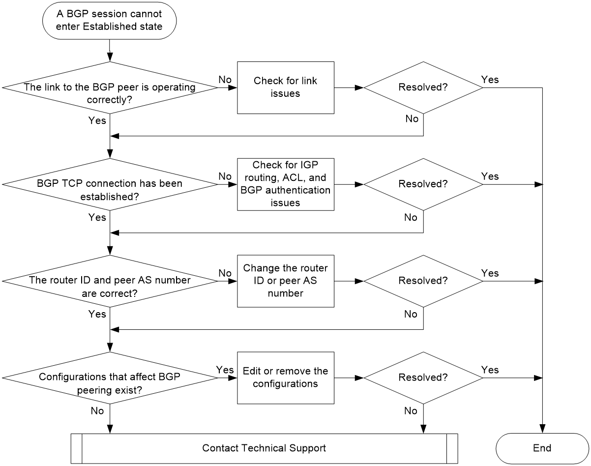
Figure 1 shows the troubleshooting flowchart:
Figure 1 Troubleshooting flowchart
Solution
1. Identify whether the link to the BGP peer is operating correctly.
a. Identify whether the peer-facing interface is in UP state.
b. Use the ping command to test connectivity with the BGP peer. If the ping succeeds, the link between the local router and the BGP peer is operating correctly. In this case, proceed to step 2. If the ping fails, proceed to step c.
|
|
NOTE: As a best practice, use the ping –a source-ip –s packet-size or ping ipv6 –a source-ipv6 –s packet-size command to test connectivity with the BGP peer. The ping method help you identify whether the links between the local and peer routers are operating correctly. The –a source-ip and –a source-ipv6 parameters specify the source IP address of ICMP echo requests. The –s packet-size parameter specifies the length of ICMP echo requests, which helps you monitor the transmission of long packets. The source IP for the ping should be the local interface IP used for BGP session establishment, and the destination IP should be the peer interface IP used for BGP session establishment. |
c. Repeat the ping –a source-ip –s packet-size command with a decreasing –s packet-size value. If the ping succeeds when the –s packet-size parameter is decreased to a certain value, the cause of this issue is that the TCP packets sent for BGP TCP connection establishment are too long and they are dropped by intermediate devices. To resolve this issue, perform either of the following tasks:
- Repeat the ping –a source-ip –s packet-size command and gradually reduce the value for the –s packet-size parameter until you find an appropriate value. As a best practice to ensure optimal forwarding efficiency, the final value should be the maximum value ensuring that the ping can succeed. Then, set the final value as the MTU value of the output interfaces for BGP packets. To achieve this goal, you can execute the ip/ipv6 mtu mtu-size or tcp mss value command on the related interfaces. Alternatively, you can execute the peer tcp-mss command in BGP instance view or BGP-VPN instance view. The ip/ipv6 mtu mtu-size command specifies the MTU value for an interface, and the peer tcp-mss command specifies the TCP MSS. You can use the following formula for TCP MSS calculation: TCP MSS = MTU - IP header length - TCP header length
- Execute the tcp path-mtu-discovery command to enable TCP path MTU discovery in system view. Then, the device dynamically obtains the smallest MTU value along the path used for TCP connection establishment, and calculates an MSS accordingly. When the device attempts to establish a BGP TCP connection, it determines the length of TCP packets based on the calculated MSS.
If the ping always fails no matter how you adjust the value for the –s packet-size parameter, troubleshoot this issue as described in the Ping failure chapter in Layer 3—IP Services Troubleshooting Guide > Ping and Tracert Troubleshooting Guide.
d. If the issue persists, proceed to step 2.
2. Identify whether a BGP TCP connection has been established between the local router and the BGP peer.
Execute the display tcp command, and then identify whether the output displays the following TCP connection:
¡ Local address: IP address of the local router.
¡ Peer address: IP address of the related BGP peer.
¡ Peer port: 179.
¡ State: ESTABLISHED.
For example:
<Sysname> display tcp
*: TCP connection with authentication
Local Addr:port Foreign Addr:port State PCB
0.0.0.0:179 12.1.1.2:0 LISTEN 0xffffffffffffff9d
12.1.1.1:28160 12.1.1.2:179 ESTABLISHED 0xffffffffffffff9e
If such a TCP connection exists, proceed to step 3. If not, perform the following checks:
¡ Execute the display ip routing-table or display ipv6 routing-table command, and then identify whether the routing table contains an IGP route to the IPv4 or IPv6 peer address used for BGP session establishment. If such a route does not exist, check for incorrect IGP routing settings. For more information about troubleshooting IGP issues, see OSPF, OSPFv3, or IS-IS troubleshooting guide in Layer 3—IP Routing Troubleshooting Guide.
¡ Execute the display acl all command to check for a rule that denies port bgp. For example:
<Sysname> display acl all
Advanced IPv4 ACL 3077, 2 rules,
ACL's step is 5
rule 1 deny tcp destination-port eq bgp
rule 2 deny tcp source-port eq bgp
If such a rule exists, execute the undo rule command to remove the rule.
¡ Execute the debugging tcp packet command to identify whether an authentication failure occurs upon TCP connection establishment. For example:
<Sysname> debugging tcp packet acl 3000
*Feb 5 20:03:39:289 2021 Sysname SOCKET/7/INET: -MDC=1;
TCP Input: Failed to check md5, drop the packet.
As shown in the command output, BGP failed to pass MD5 authentication when it attempted to initiate a TCP connection. In this situation, execute the peer password command to configure the same key at both ends of the BGP TCP connection.
<Sysname> debugging tcp packet acl 3000
*Feb 5 20:03:39:289 2021 Sysname SOCKET/7/INET: -MDC=1;
TCP Input: Failed to check keychain, drop the packet.
As shown in the command output, BGP failed to pass keychain authentication when it attempted to initiate a TCP connection. In this situation, execute the peer keychain command at both ends of the BGP TCP connection to ensure the following requirements are met:
- The keys used by the two ends at the same time must have the same ID.
- The keys with the same ID must use the same authentication algorithm and key string.
<Sysname> debugging tcp packet acl 3000
*Feb 5 20:03:39:289 2021 Sysname SOCKET/7/INET: -MDC=1;
TCP Input: Failed to get IPSEC profile, index 500, name profile1(inpcb profile2), return 0x3fff.
As shown in the command output, BGP failed to pass IPsec authentication when it attempted to initiate a TCP connection. In this situation, make sure the peer ipsec-profile command is executed at both ends of the BGP TCP connection.
If the issue persists, proceed to step 3.
3. Identify whether the local router has a router ID conflict with the peer or peer group, or whether the specified peer or peer group AS number is incorrect.
a. Execute the display bgp peer command, and then view the BGP local router ID field in the output to identify whether a router ID conflict exists. If a router ID conflict is found, execute the router-id command in the BGP instance or BGP-VPN instance that requires establishing a BGP session, to change the router ID of the BGP router.
<Sysname> display bgp peer ipv4 unicast
BGP local router ID: 12.1.1.1
Local AS number: 10
Total number of peers: 1 Peers in established state: 1
* - Dynamically created peer
Peer AS MsgRcvd MsgSent OutQ PrefRcv Up/Down State
12.1.1.2 20 3 3 0 0 00:00:25 Established
b. Execute the display bgp peer command, and then view the AS field in the output to identify whether the AS number specified for the peer or peer group is incorrect. If the AS number is incorrect, execute the peer as-number command to correct the AS number. For example:
<Sysname> display bgp peer ipv4 unicast
BGP local router ID: 12.1.1.1
Local AS number: 10
Total number of peers: 1 Peers in established state: 1
* - Dynamically created peer
Peer AS MsgRcvd MsgSent OutQ PrefRcv Up/Down State
12.1.1.2 20 3 3 0 0 00:00:25 Established
c. If the issue persists, proceed to step 4.
4. Execute the display this command in BGP instance view to check for configurations that affect BGP session establishment:
Table 1 Check items that affect BGP session establishment
|
Check Item |
Description |
|
peer { group-name | ipv4-address [ mask-length ] | ipv6-address [ prefix-length ] } connect-interface interface-type interface-number |
When this configuration exists on the local router, the BGP peer must also use a loopback interface address for BGP session establishment. To meet this requirement, you can use this command or the peer source-address command. |
|
peer ipv4-address [ mask-length ] source-address source-ipv4-address peer ipv6-address [ prefix-length ] source-address source-ipv6-address |
If this configuration exists on the local router, the BGP peer must also use a loopback interface address for BGP session establishment. To meet this requirement, you can use this command or the peer connect-interface command. |
|
peer { group-name | ipv4-address [ mask-length ] | ipv6-address [ prefix-length ] } ebgp-max-hop [ hop-count ] |
This command is required in one of the following situations: · Two indirectly-connected devices need to establish an EBGP session. · Two directly-connected devices need to establish an EBGP session through their loopback interfaces. To ensure successful EBGP session establishment, execute this command at both ends of the EBGP session. |
|
peer { group-name | ipv4-address [ mask-length ] | ipv6-address [ prefix-length ] } ttl-security hops hop-count |
If this configuration exists, the local router accepts BGP packets from the specified peer only when the TTLs of those BGP packets are within the valid TTL range. The valid TTL range is from 255 – the hop-count value + 1 to 255. If the number of hops between the local router and the specified peer exceeds the hop-count value, execute this command to adjust the hop-count value. |
|
peer { group-name | ipv4-address [ mask-length ] | ipv6-address [ prefix-length ] | link-local-address interface interface-type interface-number } route-limit prefix-number [ reconnect reconnect-time | percentage-value ] * |
If this configuration exists on the local router and the number of routes received from the specified peer or peer group exceeds the prefix-number value, the local router will disconnect from the peer or peer group. To avoid this issue, reduce the number of routes sent by the peer or peer group or increase the prefix-number value. |
|
peer { group-name | ipv4-address [ mask-length ] | ipv6-address [ prefix-length ] | link-local-address interface interface-type interface-number } ignore [ graceful graceful-time { community { community-number | aa:nn } | local-preference preference | med med } * ] |
If this configuration exists, the local router will not establish a BGP session with the specified peer or peer group. To resolve this issue, execute the undo peer ignore command with the peer or peer group specified. |
|
ignore all-peers [ graceful graceful-time { community { community-number | aa:nn } | local-preference preference | med med } * ] |
If this configuration exists, the local router cannot establish BGP sessions with any peers. In this situation, the local router might be undergoing a network upgrade or maintenance task, and the related BGP process is temporarily unavailable. As a best practice, execute the undo peer ignore or undo ignore all-peers command after the upgrade or maintenance task is completed. |
|
shutdown process |
If this configuration exists, the local router cannot establish BGP sessions with any peers. In this situation, the local router might be undergoing a network upgrade or maintenance task, and the related BGP process is temporarily unavailable. As a best practice, execute the undo shutdown process command after the upgrade or maintenance task is completed. |
|
The peer enable command in the related address family |
When two devices need to establish a BGP session, you must execute the peer enable command on each of them with the other specified. Make sure the peer enable command is executed in the same address family. If this configuration exists on the local router, verify that the peer is also configured with the peer enable command in the same address family. |
If the issue persists, proceed to step 5.
5. If the issue persists, collect the following information and contact Technical Support:
¡ Results of each step.
¡ The configuration file, log messages, and alarm messages.
Related alarm and log messages
Alarm messages
After the snmp-agent trap enable bgp command is executed in system view, the router generates the following alarm message:
Module name: BGP4-MIB
· bgpBackwardTransition (1.3.6.1.2.1.15.7.2)
Log messages
N/A
BGP session down
Symptom
The device generates a BGP/5/BGP_STATE_CHANGED log message, which notifies that the state of a BGP session transitioned from Established to Idle.
Common causes
The following are the common causes of this type of issue:
· KEEPALIVE or UPDATE message sending/receiving timed out.
· TCP connection establishment failed.
· The local device has reached a memory threshold.
· An error occurred in parsing BGP messages.
Analysis
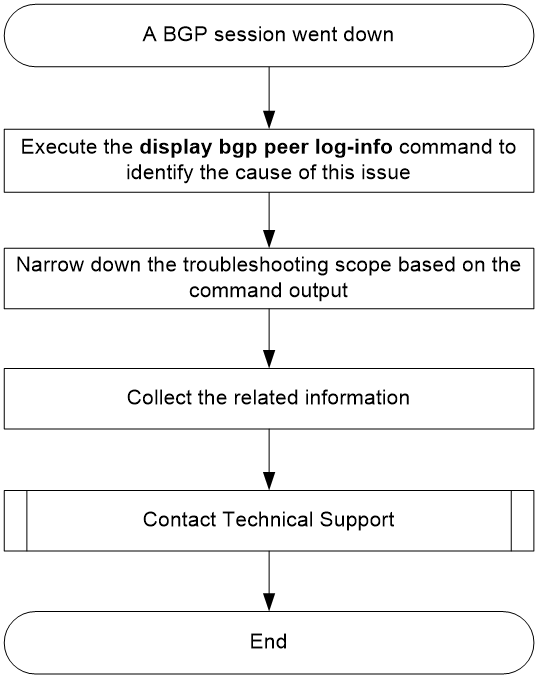
Figure 2 shows the troubleshooting flowchart:
Figure 2 Troubleshooting flowchart
Solution
Execute the display bgp peer log-info command to identify the cause of this issue. The common causes include:
· A BGP timer expired.
If the output of the display bgp peer log-info command is similar to the following:
<Sysname> display bgp peer ipv4 3.3.3.3 log-info
Peer: 3.3.3.3
Date Time State Notification
Error/SubError
17-Jan-2022 14:48:34 Down Receive notification with error 4/0
Hold Timer Expired/ErrSubCode Unspecified
Keepalive last triggered time: 14:48:31-2022.1.17
Keepalive last sent time : 14:48:31-2022.1.17
Update last sent time : 14:48:24-2022.1.17
EPOLLOUT last occurred time : 14:48:30-2022.1.17
The BGP session went down because the local router could not receive a KEEPALIVE or UPDATE message from the peer before the hold timer expired. After the hold timer expired, the local device actively terminated the BGP session and sent a NOTIFICATION message to the peer.
A timer timeout issue might occur in one of the following situations:
¡ The device sends a KEEPALIVE or UPDATE message to a peer normally, but the message fails to reach the peer or the peer does not process the message in time.
¡ The device fails to generate a KEEPALIVE or UPDATE message in time due to scheduling issues.
To resolve this issue, execute the display system internal bgp log command in probe view at both ends of the BGP session, collect the command output, and then contact Technical Support for further analysis.
· A TCP connection error occurred.
If the output of the display bgp peer log-info command is similar to the following:
<Sysname> display bgp peer ipv4 1.1.1.1 log-info
Peer: 1.1.1.1
Date Time State Notification
Error/SubError
17-Jan-2022 14:42:01 Down Receive TCP_Connection_Failed event
The BGP session went down due to a TCP connection error. If BGP uses TCP as the transport layer protocol, and a TCP connection error occurs between the two BGP peers, the related BGP session will be terminated. If the output of the display bgp peer log-info command is different from the above example, but contains a NOTIFICATION message with error code 5/0, the cause of this issue is also a TCP connection error.
After you confirm that the BGP session went down due to a TCP connection error, perform the following task:
a. Execute the view /proc/tcp/tcp_log slot x command in probe view at both ends of the BGP session (execute this command once for each card or member device).
b. Collect the command output.
c. Contact Technical Support for further analysis.
· The memory was insufficient.
If the output of the display bgp peer log-info command is similar to the following:
<Sysname> display bgp peer ipv4 1.1.1.1 log-info
Peer: 1.1.1.1
Date Time State Notification
Error/SubError
17-Jan-2022 15:38:53 Down Send notification with error 6/8
Entered severe memory state
17-Jan-2022 14:53:51 Down Send notification with error 6/8
No memory to process the attribute
The device did not have enough memory to run BGP-related functions, which caused the BGP session termination. The cause of this issue corresponds to error code 6/8 in the output of the display bgp peer log-info command.
In this case, perform the following task:
d. Execute the display memory-threshold command at both ends of the BGP session to obtain the memory alarm thresholds.
e. Collect the output of the display bgp peer log-info command.
f. Contact Technical Support for further analysis.
· An error occurred in parsing BGP messages.
If the two ends of a BGP session have different message parsing capabilities or have a version mismatch, they might not be able to parse the BGP packets received from each other and thus might be disconnected. This type of issue corresponds to error codes 1, 2, and 3 in the output of the display bgp peer log-info command (where the Error part in the Error/SubError field is 1, 2, or 3).
Execute the debugging bgp raw-packet, debugging bgp open, and debugging bgp update commands at both ends of the BGP session, collect the output of those commands and the display bgp peer log-info command, and then contact Technical Support for further analysis.
· If the cause of this issue displayed in the output of the display bgp peer log-info command is not any of the above, collect the following information and contact Technical Support:
¡ Output of the display bgp peer log-info command.
¡ Output of the display system internal bgp log command.
¡ Output of the view /proc/tcp/tcp_log slot x command (executed once for each card or member device).
¡ The configuration file, log messages, and alarm messages.
Table 2 lists the detailed reasons for BGP peer disconnection and their corresponding error codes.
Table 2 Reasons for BGP peer disconnection
|
Error code/subcode |
Reason for peer disconnection |
Description |
|
1/1 |
connection not synchronized |
The two ends of the connection were not synchronized. The current implementation is that the first 16 bytes of the received message's header do not contain only Fs. |
|
1/2 |
bad message length |
Invalid message length. |
|
1/3 |
bad message type |
Invalid message type. |
|
3/1 |
the withdrawn length is too large |
The length of routing information to be withdrawn was too long. |
|
the attribute length is too large |
The attribute length was too long. |
|
|
one attribute appears more than once |
A path attribute appeared multiple times in an UPDATE message. |
|
|
the attribute length is too small |
The attribute length was less than two bytes. |
|
|
exntended length field is less than two octets |
The attribute length was extensible, but it was less than two bytes. |
|
|
the length field is less than one octet |
The attribute length was not extensible, but it was less than one byte. |
|
|
link-state attribute error |
The link-state attribute was in incorrect form. |
|
|
3/2 |
unrecognized well-known attribute |
Unknown well-known attribute. |
|
3/3 |
attribute-type attribute missed |
The attribute-type attribute was lost. The values for the attribute-type argument include: · ORIGIN · AS_PATH · LOCAL_PREF · NEXT_HOP |
|
3/4 |
attribute flags error |
Incorrect attribute flags. |
|
3/5 |
attribute-type attribute length error |
The length of the attribute-type attribute was invalid. The values for the attribute-type argument include: · AS_PATH · AS4_PATH · CLUSTER_LIST · AGGREGATOR · AS4_AGGREGATOR · ORIGIN · NEXT_HOP · MED · LOCAL_PREF · ATOMIC_AGGREGATE · ORIGINATOR_ID · MP_REACH_NLRI · COMMUNITIES · EXT-COMMUNITIES |
|
attribute length exceeds |
The attribute length crossed the limit. |
|
|
3/6 |
invalid ORIGIN attribute |
Invalid ORIGIN attribute. |
|
3/8 |
invalid NEXT_HOP attribute |
Invalid NEXT_HOP attribute. |
|
3/9 |
invalid nexthop length in MP_REACH_NLRI (address-family) |
The Nexthop length in the MP_REACH_NLRI attribute was invalid for the address-family address family. The values for the address-family argument include: · 4u—IPv4 unicast address family. · IPv4 Flowspec—IPv4 flowspec address family. · MPLS—MPLS address family. · VPNv4—VPNv4 address family · 6u—IPv6 unicast address family. · VPNv6—VPNv6 address family. · L2VPN—L2VPN address family. |
|
the length of MP_UNREACH_NLRI is too small |
The length of the MP_UNREACH_NLRI attribute was less than three bytes. |
|
|
the MP NLRI attribute length exceeds |
The length of the MP_REACH_NLRI or MP_UNREACH_NLRI attribute crossed the limit. |
|
|
erroneous MP NLRI attribute end position |
The reachable or unreachable prefix and the path attribute ended at different positions. |
|
|
3/10 |
invalid network field |
Invalid network field. |
|
3/11 |
malformed AS_PATH |
The AS_PATH attribute was malformed. |
|
4/0 |
Keepalive last triggered time |
Most recent time when KEEPALIVE message sending was triggered. |
|
Keepalive last sent time |
Most recent time when a KEEPALIVE message was sent. |
|
|
Update last sent time |
Most recent time when an UPDATE message was sent. |
|
|
EPOLLOUT last occurred time |
Most recent time when an EPOLLOUT event occurred. |
|
|
Keepalive last received time |
Most recent time when a KEEPALIVE message was received. |
|
|
Update last received time |
Most recent time when an UPDATE message was received. |
|
|
EPOLLIN last occurred time |
Most recent time when an EPOLLIN event occurred. |
|
|
5/0 |
connection retry timer expires |
The ConnectRetry timer expired. |
|
TCP_CR_Acked event received |
A TCP_CR_Acked event was received. |
|
|
TCP_Connection_Confirmed event received |
A TCP_Connection_Confirmed event was received. |
|
|
5/3 |
open message received |
An OPEN message was received. |
|
6/0 |
manualstop event received |
A manualstop event was received. |
|
physical interface configuration changed |
Physical configurations changed, such as interface settings. |
|
|
session down event received from BFD |
A BFD session down event was received. |
|
|
6/1 |
maximum number of prefixes reached |
The number of route prefixes has exceeded the upper limit specified by using the peer route-limit command. |
|
maximum number of address-family prefixes reached |
The number of route prefixes in the address-family address family has exceeded the upper limit specified by using the peer route-limit command. The values for the address-family argument include: · IPv4 unicast—IPv4 unicast address family. · IPv6 unicast—IPv6 unicast address family. · VPNv4—VPNv4 address family. · VPNv6—VPNv6 address family. |
|
|
6/2 |
configuration of peer ignore changed |
The peer ignore command was configured. |
|
6/3 |
address family deleted |
An address family was deleted. |
|
peer disabled |
A peer was disabled. |
|
|
6/4 |
administrative reset |
The BGP session was reset because of the reset bgp command or configuration changes. |
|
6/5 |
connection rejected |
The connection request was rejected. |
|
6/6 |
other configuration change |
Other configurations changed. |
|
6/7 |
connection collision resolution |
A connection conflict occurred. |
|
two connections exist and MD5 authentication is configured for the neighbor |
Two connections existed and MD5 authentication was configured for one of them. |
|
|
6/8 |
no memory to process the attribute |
The memory was insufficient for attribute parsing. |
|
no memory for the route |
Failed to obtain memory resources for route or label block generation. |
|
|
no memory to generate unreachable NLRI |
Failed to obtain memory resources for MP_UNREACH_NLRI encapsulation. |
|
|
no memory to generate a message |
Failed to obtain memory resources for message encapsulation. |
|
|
can't get the VPN RD |
Failed to obtain RDs upon prefix parsing. |
|
|
can't get the VPN routing table |
Failed to obtain the VPN routing table upon prefix parsing. |
|
|
can't get the attributes |
Failed to obtain attributes upon prefix parsing. |
|
|
entered severe memory state |
A severe memory usage alarm was triggered. |
|
|
entered critical memory state |
A critical memory usage alarm was triggered. |
Related alarm and log messages
Alarm messages
N/A
Log messages
· BGP/5/BGP_STATE_CHANGED
· BGP/5/BGP_STATE_CHANGED_REASON
· BGP/6/BGP_PEER_STATE_CHG
BGP routing loop in a cross-AS data center interconnect scenario
Symptom
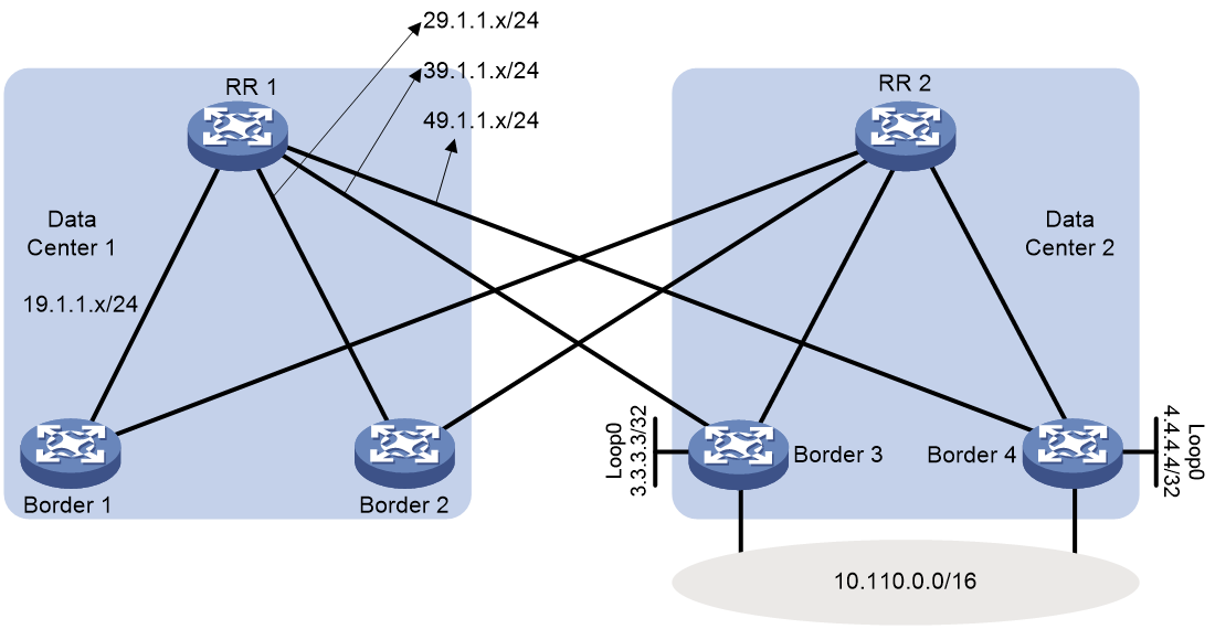
As shown in Figure 3, two data centers are interconnected across ASs through BGP. RR 1 learns BGP routes with the same prefix (for example, 10.110.0.0/16) from Border 3 and Border 4 in Data Center 2. The next hops for those routes are the loopback interface addresses of Border 3 and Border 4, respectively. RR 1 selects the route from Border 3 or Border 4 as the optimal route. Border 1 and Border 2 send default routes to RR 1 through BGP, with the next hops being IP addresses of the interfaces directly connected to RR 1. If Border 3 or Border 4 restarts, the devices in Data Center 1 cannot access network segment 10.110.0.0/16 during the restart. Packets destined for the network segment loop between RR 1 and Border 1 or RR 1 and Border 2.
Common causes
Before Border 3 or Border 4 restarts, the BGP routing table and IP routing table of RR 1 are similar to the following:
<RR1> display bgp routing-table ipv4
Total number of routes: 4
BGP local router ID is 9.9.9.9
Status codes: * - valid, > - best, d - dampened, h - history,
s - suppressed, S - stale, i - internal, e - external
a - additional-path
Origin: i - IGP, e - EGP, ? - incomplete
Network NextHop MED LocPrf PrefVal Path/Ogn
* >i 0.0.0.0/0 19.1.1.1 100 0 i
* i 29.1.1.2 100 0 i
* >e 10.110.0.0/16 3.3.3.3 0 0 20i
* e 4.4.4.4 0 0 20i
<RR1> display ip routing-table
Destinations : 25 Routes : 25
Destination/Mask Proto Pre Cost NextHop Interface
0.0.0.0/0 BGP 255 0 19.1.1.1 GE0/0/1
0.0.0.0/32 Direct 0 0 127.0.0.1 InLoop0
1.1.1.1/32 O_INTRA 10 1 19.1.1.1 GE0/0/1
2.2.2.2/32 O_INTRA 10 1 29.1.1.2 GE0/0/2
3.3.3.3/32 O_INTRA 10 1 39.1.1.3 GE0/0/3
4.4.4.4/32 O_INTRA 10 1 49.1.1.4 GE0/0/4
9.9.9.9/32 Direct 0 0 127.0.0.1 InLoop0
10.10.10.10/32 BGP 255 0 1.1.1.1 GE0/0/1
19.1.1.0/24 Direct 0 0 19.1.1.9 GE0/0/1
19.1.1.0/32 Direct 0 0 19.1.1.9 GE0/0/1
19.1.1.9/32 Direct 0 0 127.0.0.1 InLoop0
19.1.1.255/32 Direct 0 0 19.1.1.9 GE0/0/1
10.110.0.0/16 BGP 255 0 3.3.3.3 GE0/0/3
29.1.1.0/24 Direct 0 0 29.1.1.9 GE0/0/2
29.1.1.0/32 Direct 0 0 29.1.1.9 GE0/0/2
29.1.1.9/32 Direct 0 0 127.0.0.1 InLoop0
29.1.1.255/32 Direct 0 0 29.1.1.9 GE0/0/2
39.1.1.0/24 Direct 0 0 39.1.1.9 GE0/0/3
39.1.1.0/32 Direct 0 0 39.1.1.9 GE0/0/3
39.1.1.9/32 Direct 0 0 127.0.0.1 InLoop0
39.1.1.255/32 Direct 0 0 39.1.1.9 GE0/0/3
49.1.1.0/24 Direct 0 0 29.1.1.9 GE0/0/2
49.1.1.0/32 Direct 0 0 29.1.1.9 GE0/0/2
49.1.1.9/32 Direct 0 0 127.0.0.1 InLoop0
49.1.1.255/32 Direct 0 0 29.1.1.9 GE0/0/2
127.0.0.0/8 Direct 0 0 127.0.0.1 InLoop0
127.0.0.0/32 Direct 0 0 127.0.0.1 InLoop0
127.0.0.1/32 Direct 0 0 127.0.0.1 InLoop0
127.255.255.255/32 Direct 0 0 127.0.0.1 InLoop0
255.255.255.255/32 Direct 0 0 127.0.0.1 InLoop0
According to the above command output, RR 1 learned routes destined for the loopback interfaces of Border 3 and Border 4 through IGP. BGP network route 10.110.0.0/16 was iterated to the learned loopback interface routes.
After Border 4 restarts, RR 1 does not disconnect from Border 4 unless the session hold timer expires, and the routing table of RR 1 still retain network route 10.110.0.0/16 (received from Border 4). However, the network route can be iterated only to the default route (0.0.0.0/0), because the IGP route for next hop 4.4.4.4 has become invalid and RR 1 does not have other network routes that contain IP address 4.4.4.4.
In the routing table of RR 1, you can find the following information:
· The IGP metric value is 1 for the next hop of network route 10.110.0.0/16 received from Border 3, which corresponds to route entry 3.3.3.3/32 O_INTRA 10 1 39.1.1.3 GE0/0/3.
· The IGP metric value is 0 for the next hop of network route 10.110.0.0/16 received from Border 4, which corresponds to route entry 0.0.0.0/0 BGP 255 0 19.1.1.1 GE0/0/1.
According to the BGP route selection rules, RR 1 chooses the route from Border 4 as the optimal route. In the forwarding table, the next hop for network segment 10.110.0.0/16 changes to GigabitEthernet0/0/1. Consequently, RR 1 forwards packets destined for network segment 10.110.0.0/16 to Border 1. Then, Border 1 forwards those packets back to RR 1, because Border 1 learned network route 10.110.0.0/16 from RR 1. This causes a routing loop.
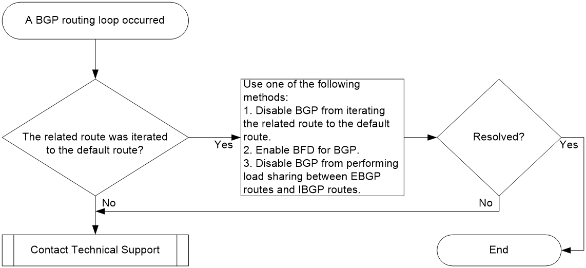
Analysis
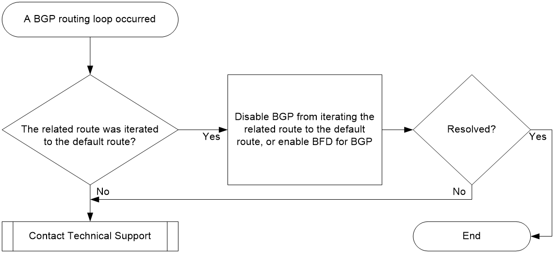
Figure 4 shows the troubleshooting flowchart:
Figure 4 Troubleshooting flowchart
Solution
1. View the BGP routing table and IP routing table of RR 1. This example uses the network shown in Figure 3 for illustration.
a. After Border 4 restarts, if you execute the display bgp routing-table ipv4 command on RR 1 before RR 1 is disconnected from Border 4, you can find that network route 10.110.0.0/16 received from Border 4 is still active and is the optimal route.
<RR1> display bgp routing-table ipv4
Total number of routes: 5
BGP local router ID is 9.9.9.9
Status codes: * - valid, > - best, d - dampened, h - history,
s - suppressed, S - stale, i - internal, e - external
a - additional-path
Origin: i - IGP, e - EGP, ? - incomplete
Network NextHop MED LocPrf PrefVal Path/Ogn
* >i 0.0.0.0/0 19.1.1.1 100 0 i
* i 29.1.1.2 100 0 i
* >e 10.110.0.0/16 4.4.4.4 0 0 20i
* e 3.3.3.3 0 0 20i
b. After you execute the display ip routing-table verbose command on RR 1, you can find that the output interface and real next hop for network route 10.110.0.0/16 have changed to the interface (GigabitEthernet0/0/1) directly connected to Border 1 and the interface’s IP address (19.1.1.1), respectively.
<RR1> display ip routing-table 10.110.0.0/16 verbose
Summary count : 1
Destination: 10.110.0.0/16
Protocol: BGP instance default
Process ID: 0
SubProtID: 0x6 Age: 00h00m19s
FlushedAge: 00h00m19s
Cost: 0 Preference: 255
IpPre: N/A QosLocalID: N/A
Tag: 0 State: Active Adv
OrigTblID: 0x0 OrigVrf: default-vrf
TableID: 0x2 OrigAs: 20
NibID: 0x16000002 LastAs: 20
AttrID: 0x2
BkAttrID: 0xffffffff Neighbor: 4.4.4.4
Flags: 0x10060 OrigNextHop: 4.4.4.4
Label: NULL RealNextHop: 19.1.1.1
BkLabel: NULL BkNextHop: N/A
SRLabel: NULL Interface: GigabitEthernet0/0/1
BkSRLabel: NULL BkInterface: N/A
Tunnel ID: Invalid IPInterface: GigabitEthernet0/0/1
BkTunnel ID: Invalid BkIPInterface: N/A
InLabel: NULL ColorInterface: N/A
SIDIndex: NULL BkColorInterface: N/A
FtnIndex: 0x0 TunnelInterface: N/A
TrafficIndex: N/A BkTunnelInterface: N/A
Connector: N/A PathID: 0x0
UserID: 0x0 SRTunnelID: Invalid
SID Type: N/A NID: Invalid
FlushNID: Invalid BkNID: Invalid
BkFlushNID: Invalid StatFlags: 0x0
SID: N/A
BkSID: N/A
CommBlockLen: 0 Priority: Low
MemberPort: N/A
c. After you execute the display ip routing-table command, you can find the following information:
- The IP routing table does not contain other network routes that contain IP address 4.4.4.4.
- The output interface and next hop IP for the default route are GigabitEthernet0/0/1 and 19.1.1.1, respectively.
This indicates that network route 10.110.0.0/16 received from Border 4 has been iterated to the default route.
<RR1> display ip routing-table
Destinations : 25 Routes : 25
Destination/Mask Proto Pre Cost NextHop Interface
0.0.0.0/0 BGP 255 0 19.1.1.1 GE0/0/1
0.0.0.0/32 Direct 0 0 127.0.0.1 InLoop0
1.1.1.1/32 O_INTRA 10 1 19.1.1.1 GE0/0/1
2.2.2.2/32 O_INTRA 10 1 29.1.1.2 GE0/0/2
3.3.3.3/32 O_INTRA 10 1 39.1.1.3 GE0/0/3
9.9.9.9/32 Direct 0 0 127.0.0.1 InLoop0
10.10.10.10/32 BGP 255 0 1.1.1.1 GE0/0/1
19.1.1.0/24 Direct 0 0 19.1.1.9 GE0/0/1
19.1.1.0/32 Direct 0 0 19.1.1.9 GE0/0/1
19.1.1.9/32 Direct 0 0 127.0.0.1 InLoop0
19.1.1.255/32 Direct 0 0 19.1.1.9 GE0/0/1
10.110.0.0/16 BGP 255 0 4.4.4.4 GE0/0/1
29.1.1.0/24 Direct 0 0 29.1.1.9 GE0/0/2
29.1.1.0/32 Direct 0 0 29.1.1.9 GE0/0/2
29.1.1.9/32 Direct 0 0 127.0.0.1 InLoop0
29.1.1.255/32 Direct 0 0 29.1.1.9 GE0/0/2
39.1.1.0/24 Direct 0 0 39.1.1.9 GE0/0/3
39.1.1.0/32 Direct 0 0 39.1.1.9 GE0/0/3
39.1.1.9/32 Direct 0 0 127.0.0.1 InLoop0
39.1.1.255/32 Direct 0 0 39.1.1.9 GE0/0/3
49.1.1.0/24 Direct 0 0 29.1.1.9 GE0/0/2
49.1.1.0/32 Direct 0 0 29.1.1.9 GE0/0/2
49.1.1.9/32 Direct 0 0 127.0.0.1 InLoop0
49.1.1.255/32 Direct 0 0 29.1.1.9 GE0/0/2
127.0.0.0/8 Direct 0 0 127.0.0.1 InLoop0
127.0.0.0/32 Direct 0 0 127.0.0.1 InLoop0
127.0.0.1/32 Direct 0 0 127.0.0.1 InLoop0
127.255.255.255/32 Direct 0 0 127.0.0.1 InLoop0
255.255.255.255/32 Direct 0 0 127.0.0.1 InLoop0
If none of the above situations exists, contact Technical Support for help.
2. Use one of the following methods to remove the routing loop:
¡ Configure routing policies to filter recursive routes.
Execute the protocol bgp nexthop recursive-lookup route-policy route-policy-name command in RIB IPv4 address family view. This operation ensures that all BGP IPv4 network routes are iterated only to routes that can pass the routing policy specified by the route-policy-name argument.
Similarly, execute the protocol bgp4+ nexthop recursive-lookup route-policy route-policy-name command in RIB IPv6 address family view. This operation ensures that all BGP IPv6 network routes are iterated only to routes that can pass the routing policy specified by the route-policy-name argument.
In this scenario, create a routing policy on RR 1 that filters out the default route, and execute the protocol bgp nexthop recursive-lookup route-policy route-policy-name or protocol bgp nexthop recursive-lookup route-policy route-policy-name command to apply the routing policy. This configuration eliminates the BGP routing loop by preventing BGP routes from being iterated to the default route.
¡ Enable BFD for BGP.
After BFD is enabled for BGP, RR 1 uses BFD sessions to monitor the links to Border 3 and Border 4. If Border 3 or Border 4 restarts, BFD will detect link failures immediately. In this case, RR 1 will promptly terminate the related BGP session and delete the routes learned from Border 3 or Border 4. To enable BFD for BGP, execute the peer bfd command. For more information about this task, see the command reference.
3. If the issue persists, collect the following information and contact Technical Support:
¡ Results of each step.
¡ The configuration file, log messages, and alarm messages.
Related alarm and log messages
Alarm messages
N/A
Log messages
N/A
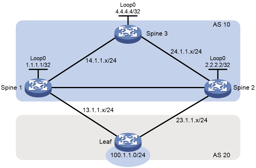
BGP routing loop in a cross-AS spine-leaf interconnect scenario
Symptom
As shown in Figure 5, the spine devices and the leaf device are in different ASs. The spine devices are fully meshed. Spine 1 and Spine 2 each establish an EBGP connection with the leaf device. Spine 2 is enabled with load balancing and can perform load balancing across EBGP and IBGP routes. When Spine 1 restarts, traffic is routed to the leaf device via Spine 2, and half of the traffic is lost.
Common causes
Before Spine 1 restarts, the BGP routing table of Spine 2 is similar to the following:
<Spine2> display bgp routing-table ipv4
Total number of routes: 3
BGP local router ID is 2.2.2.2
Status codes: * - valid, > - best, d - dampened, h - history,
s - suppressed, S - stale, i - internal, e - external
a - additional-path
Origin: i - IGP, e - EGP, ? - incomplete
Network NextHop MED LocPrf PrefVal Path/Ogn
* >i 0.0.0.0/0 24.1.1.4 100 0 i
* >e 100.1.1.0/24 23.1.1.3 0 0 20i
* i 1.1.1.1 0 100 0 20i
Spine 2 receives network route 100.1.1.0/24 from both the leaf device (23.1.1.3) and Spine 1 (1.1.1.1). The next hop for the route received from Spine 1 is a loopback interface address of Spine 1.
The IP routing table of Spine 2 is similar to the following:
<Spine2> display ip routing-table
Destinations : 24 Routes : 25
Destination/Mask Proto Pre Cost NextHop Interface
0.0.0.0/0 BGP 255 0 24.1.1.4 GE0/0/1
0.0.0.0/32 Direct 0 0 127.0.0.1 InLoop0
1.1.1.1/32 O_INTRA 10 1 12.1.1.1 GE0/0/2
2.2.2.2/32 Direct 0 0 127.0.0.1 InLoop0
4.4.4.4/32 O_INTRA 10 1 24.1.1.4 GE0/0/1
12.1.1.0/24 Direct 0 0 12.1.1.2 GE0/0/2
12.1.1.0/32 Direct 0 0 12.1.1.2 GE0/0/2
12.1.1.2/32 Direct 0 0 127.0.0.1 InLoop0
12.1.1.255/32 Direct 0 0 12.1.1.2 GE0/0/2
14.1.1.0/24 O_INTRA 10 2 12.1.1.1 GE0/0/2
O_INTRA 10 2 24.1.1.4 GE0/0/1
23.1.1.0/24 Direct 0 0 23.1.1.2 GE0/0/3
23.1.1.0/32 Direct 0 0 23.1.1.2 GE0/0/3
23.1.1.2/32 Direct 0 0 127.0.0.1 InLoop0
23.1.1.255/32 Direct 0 0 23.1.1.2 GE0/0/3
24.1.1.0/24 Direct 0 0 24.1.1.2 GE0/0/1
24.1.1.0/32 Direct 0 0 24.1.1.2 GE0/0/1
24.1.1.2/32 Direct 0 0 127.0.0.1 InLoop0
24.1.1.255/32 Direct 0 0 24.1.1.2 GE0/0/1
100.1.1.0/24 BGP 255 0 23.1.1.3 GE0/0/3
127.0.0.0/8 Direct 0 0 127.0.0.1 InLoop0
127.0.0.0/32 Direct 0 0 127.0.0.1 InLoop0
127.0.0.1/32 Direct 0 0 127.0.0.1 InLoop0
127.255.255.255/32 Direct 0 0 127.0.0.1 InLoop0
255.255.255.255/32 Direct 0 0 127.0.0.1 InLoop0
For network route 100.1.1.0/24 received from the leaf device, the IGP route to its next hop is 23.1.1.0/24, and the IGP metric is 0. For network route 100.1.1.0/24 received from Spine 1, the IGP route to its next hop is 1.1.1.1/32, and the IGP metric is 1. The two network routes 100.1.1.0/24 cannot establish a load balancing relationship in the BGP routing table, because their IGP metrics are different. This is desired by the network administrator: Spine 2 forwards traffic destined for network segment 100.1.1.0/24 to the leaf device rather than Spine 1.
Spine 3 advertises a default route to Spine 2 through BGP, and the next hop of the default route is the interface IP address directly connected to Spine 2. After Spine 1 restarts, Spine 2 retains the session to Spine 1 unless the session hold timer expires, and the routing table of Spine 2 still retain network route 100.1.1.0/24 received from Spine 1. However, the network route can be iterated only to the default route (0.0.0.0/0), because the IGP route for next hop 1.1.1.1 has become invalid and Spine 2 does not have other network routes that contain IP address 1.1.1.1.
In the BGP routing table of Spine 2, the IGP metric value is 0 for the next hop of network route 100.1.1.0/24 from Spine 1, which corresponds to route entry 0.0.0.0/0 BGP 255 0 24.1.1.4 GE0/0/1. Network routes 100.1.1.0/24 from Spine 1 and the leaf device have the same IGP metric value, so they can establish a load balancing relationship. After traffic destined for network segment 100.1.1.0/24 arrives at Spine 2, half of the traffic is distributed to Spine 3. Then, Spine 3 forwards the traffic back to Spine 2, because Spine 3 learned network route 100.1.1.0/24 from Spine 1 and Spine 2. This causes a routing loop and route loss.
Analysis
Figure 6 shows the troubleshooting flowchart:
Figure 6 Troubleshooting flowchart
Solution
1. View the BGP routing table and IP routing table of Spine 2. This example uses the network shown in Figure 5 for illustration.
a. After Spine 1 restarts, if you execute the display bgp routing-table ipv4 command on Spine 2 before Spine 2 is disconnected from Spine 1, you can find that two network routes 10.110.0.0/24 received from different devices are simultaneously selected as optimal routes.
<Spine2> display bgp routing-table ipv4
Total number of routes: 3
BGP local router ID is 2.2.2.2
Status codes: * - valid, > - best, d - dampened, h - history,
s - suppressed, S - stale, i - internal, e - external
a - additional-path
Origin: i - IGP, e - EGP, ? - incomplete
Network NextHop MED LocPrf PrefVal Path/Ogn
* >i 0.0.0.0/0 24.1.1.4 100 0 i
* >e 100.1.1.0/24 23.1.1.3 0 0 20i
* >i 1.1.1.1 0 100 0 20i
b. After you execute the display ip routing-table verbose command on Spine 2, you can find the following information:
- The two network routes 10.110.0.0/24 have established a load balancing relationship.
- For one of the routes, the real next hop is interface IP address 24.1.1.4 of Spine 3, and the output interface is the interface that directly connects Spine 2 to Spine 3.
<Spine2> display ip routing-table 100.1.1.0/24 verbose
Summary count : 2
Destination: 100.1.1.0/24
Protocol: BGP instance default
Process ID: 0
SubProtID: 0x5 Age: 00h00m13s
FlushedAge: 00h00m13s
Cost: 0 Preference: 255
IpPre: N/A QosLocalID: N/A
Tag: 0 State: Active Adv
OrigTblID: 0x0 OrigVrf: default-vrf
TableID: 0x2 OrigAs: 20
NibID: 0x16000002 LastAs: 10
AttrID: 0x2
BkAttrID: 0xffffffff Neighbor: 1.1.1.1
Flags: 0x10060 OrigNextHop: 1.1.1.1
Label: NULL RealNextHop: 24.1.1.4
BkLabel: NULL BkNextHop: N/A
SRLabel: NULL Interface: GigabitEthernet0/0/1
BkSRLabel: NULL BkInterface: N/A
Tunnel ID: Invalid IPInterface: GigabitEthernet0/0/1
BkTunnel ID: Invalid BkIPInterface: N/A
InLabel: NULL ColorInterface: N/A
SIDIndex: NULL BkColorInterface: N/A
FtnIndex: 0x0 TunnelInterface: N/A
TrafficIndex: N/A BkTunnelInterface: N/A
Connector: N/A PathID: 0x0
UserID: 0x0 SRTunnelID: Invalid
SID Type: N/A NID: Invalid
FlushNID: Invalid BkNID: Invalid
BkFlushNID: Invalid StatFlags: 0x0
SID: N/A
BkSID: N/A
CommBlockLen: 0 Priority: Low
MemberPort: N/A
Destination: 100.1.1.0/24
Protocol: BGP instance default
Process ID: 0
SubProtID: 0x6 Age: 01h18m22s
FlushedAge: 00h00m13s
Cost: 0 Preference: 255
IpPre: N/A QosLocalID: N/A
Tag: 0 State: Active Adv
OrigTblID: 0x0 OrigVrf: default-vrf
TableID: 0x2 OrigAs: 20
NibID: 0x16000000 LastAs: 20
AttrID: 0x0
BkAttrID: 0xffffffff Neighbor: 23.1.1.3
Flags: 0x10060 OrigNextHop: 23.1.1.3
Label: NULL RealNextHop: 23.1.1.3
BkLabel: NULL BkNextHop: N/A
SRLabel: NULL Interface: GigabitEthernet0/0/3
BkSRLabel: NULL BkInterface: N/A
Tunnel ID: Invalid IPInterface: GigabitEthernet0/0/3
BkTunnel ID: Invalid BkIPInterface: N/A
InLabel: NULL ColorInterface: N/A
SIDIndex: NULL BkColorInterface: N/A
FtnIndex: 0x0 TunnelInterface: N/A
TrafficIndex: N/A BkTunnelInterface: N/A
Connector: N/A PathID: 0x0
UserID: 0x0 SRTunnelID: Invalid
SID Type: N/A NID: Invalid
FlushNID: Invalid BkNID: Invalid
BkFlushNID: Invalid StatFlags: 0x0
SID: N/A
BkSID: N/A
CommBlockLen: 0 Priority: Low
MemberPort: N/A
c. After you execute the display ip routing-table command, you can find the following information:
- The IP routing table does not contain other network routes that contain IP address 1.1.1.1.
- The output interface and next hop IP for the default route are GigabitEthernet0/0/1 and 24.1.1.4, respectively.
This indicates that network route 100.1.1.0/24 received from Spine 1 has been iterated to the default route.
<Spine2> display ip routing-table
Destinations : 23 Routes : 24
Destination/Mask Proto Pre Cost NextHop Interface
0.0.0.0/0 BGP 255 0 24.1.1.4 GE0/0/1
0.0.0.0/32 Direct 0 0 127.0.0.1 InLoop0
2.2.2.2/32 Direct 0 0 127.0.0.1 InLoop0
4.4.4.4/32 O_INTRA 10 1 24.1.1.4 GE0/0/1
12.1.1.0/24 Direct 0 0 12.1.1.2 GE0/0/2
12.1.1.0/32 Direct 0 0 12.1.1.2 GE0/0/2
12.1.1.2/32 Direct 0 0 127.0.0.1 InLoop0
12.1.1.255/32 Direct 0 0 12.1.1.2 GE0/0/2
14.1.1.0/24 O_INTRA 10 2 24.1.1.4 GE0/0/1
23.1.1.0/24 Direct 0 0 23.1.1.2 GE0/0/3
23.1.1.0/32 Direct 0 0 23.1.1.2 GE0/0/3
23.1.1.2/32 Direct 0 0 127.0.0.1 InLoop0
23.1.1.255/32 Direct 0 0 23.1.1.2 GE0/0/3
24.1.1.0/24 Direct 0 0 24.1.1.2 GE0/0/1
24.1.1.0/32 Direct 0 0 24.1.1.2 GE0/0/1
24.1.1.2/32 Direct 0 0 127.0.0.1 InLoop0
24.1.1.255/32 Direct 0 0 24.1.1.2 GE0/0/1
100.1.1.0/24 BGP 255 0 1.1.1.1 GE0/0/1
BGP 255 0 23.1.1.3 GE0/0/3
127.0.0.0/8 Direct 0 0 127.0.0.1 InLoop0
127.0.0.0/32 Direct 0 0 127.0.0.1 InLoop0
127.0.0.1/32 Direct 0 0 127.0.0.1 InLoop0
127.255.255.255/32 Direct 0 0 127.0.0.1 InLoop0
255.255.255.255/32 Direct 0 0 127.0.0.1 InLoop0
If none of the above situations exists, contact Technical Support for help.
2. Use one of the following methods to remove the routing loop:
¡ Configure routing policies to filter recursive routes.
Execute the protocol bgp nexthop recursive-lookup route-policy route-policy-name command in RIB IPv4 address family view. This operation ensures that all BGP IPv4 network routes are iterated only to routes that can pass the routing policy specified by the route-policy-name argument.
Similarly, execute the protocol bgp4+ nexthop recursive-lookup route-policy route-policy-name command in RIB IPv6 address family view. This operation ensures that all BGP IPv6 network routes are iterated only to routes that can pass the routing policy specified by the route-policy-name argument.
In this scenario, create a routing policy on Spine 2 that filters out the default route, and execute the protocol bgp nexthop recursive-lookup route-policy route-policy-name or protocol bgp nexthop recursive-lookup route-policy route-policy-name command to apply the routing policy. This configuration eliminates the BGP routing loop by preventing BGP routes from being iterated to the default route.
¡ Enable BFD for BGP.
After BFD is enabled for BGP, Spine 1 and Spine 2 uses a BFD session to monitor their link. If Spine 1 restarts, BFD will detect a link failure immediately. In this case, Spine 2 will promptly terminate the related BGP session and delete the routes learned from Spine 1. To enable BFD for BGP, execute the peer bfd command. For more information about this task, see the command reference.
¡ Verify that EBGP and IBGP routes cannot establish a load balancing relationship.
In this example, the two routes for network segment 100.1.1.0/24 are learned from an IBGP peer and an EBGP peer, respectively. When you configure the balance command in the related BGP instance, do not specify the eibgp keyword. Without this keyword specified, Spine 2 selects only network route 100.1.1.0/24 received from the leaf device as the optimal route, according to the BGP route selection rules. This ensures that all traffic can be forwarded correctly.
3. If the issue persists, collect the following information and contact Technical Support:
¡ Results of each step.
¡ The configuration file, log messages, and alarm messages.
Related alarm and log messages
Alarm messages
N/A
Log messages
N/A
Public traffic interrupted in BGP network
Symptom
Public traffic is interrupted when it is forwarded through BGP.
Common causes
The following are the common causes of this type of issue:
· The next hop of the related BGP public route is unreachable.
· The distribution or reception policy for BGP public routes is inappropriate.
· The related route is discarded, because the number of BGP public routes has exceeded the maximum number of routes that the device can receive.
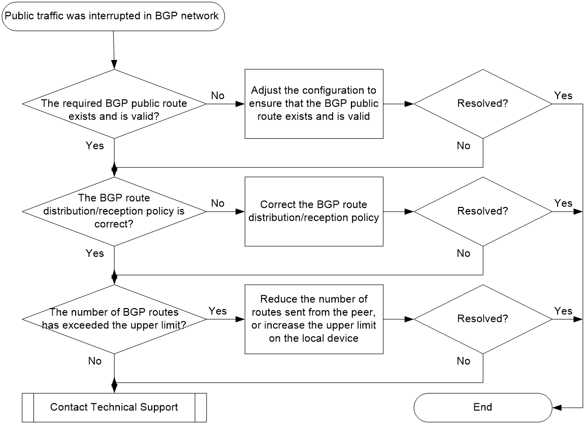
Analysis
Figure 7 shows the troubleshooting flowchart:
Figure 7 Troubleshooting flowchart
Solution
1. Identify whether the required BGP public route exists and is valid.
Based on the next hop of the BGP route, the expected forwarding path for public network traffic, and the network topology plan, locate the sender of the BGP public route. On the sender, execute the display bgp routing-table ipv4 unicast or display bgp routing-table ipv6 unicast command to view BGP public route information.
a. If the required BGP public route does not exist, use the import-route or network command to generate the route. After the BGP route is generated or if the required BGP public route already exists, proceed to step b.
b. Identify whether the required BGP public route is valid. A BGP route is valid only if it has a reachable next hop. Take route 10.2.1.0/24 as an example. If this route is marked with an asterisk (*) in the command output, it is a valid route.
<Sysname> display bgp routing-table ipv4 unicast
Total number of routes: 4
BGP local router ID is 192.168.100.1
Status codes: * - valid, > - best, d - dampened, h - history
s - suppressed, S - stale, i - internal, e - external
a – additional-path
Origin: i - IGP, e - EGP, ? - incomplete
Network NextHop MED LocPrf PrefVal Path/Ogn
* > 10.2.1.0/24 10.2.1.1 0 0 i
e 10.2.1.2 0 0 4294967295 i
View the command output to identify whether the required BGP public route is valid.
- If the BGP public route is invalid, the IP routing table does not have a route to the next hop of the BGP route. In this case, check for incorrect IP routing settings (IGP or static routing settings), and make sure the IP routing table contains a route to the next hop of the BGP route.
- If the BGP public route is valid, proceed to step 2.
2. Identify whether the distribution or reception policy for BGP public routes is inappropriate.
Based on the next hop of the BGP route, the expected forwarding path for public network traffic, and the network topology plan, locate the sender and receiver of the BGP public route. On both of the sender and receiver, execute the display current-configuration configuration bgp command to view the effective BGP settings.
As shown in the following command output, the commands that define BGP route distribution or reception include:
¡ peer prefix-list
¡ peer filter-policy
¡ peer as-path-acl
¡ filter-policy
¡ peer route-policy
<Sysname> display current-configuration configuration bgp
#
bgp 20
peer 12.1.1.1 as-number 10
peer 23.1.1.3 as-number 30
#
address-family ipv4 unicast
filter-policy 2088 export
network 9.9.9.9 255.255.255.255
peer 12.1.1.1 enable
peer 12.1.1.1 filter-policy 2077 export
peer 12.1.1.1 route-policy test export
peer 23.1.1.3 as-path-acl 2 export
peer 23.1.1.3 enable
peer 23.1.1.3 next-hop-local
peer 23.1.1.3 prefix-list abc export
#
return
For more information about these commands, see BGP commands in Layer 3—IP Routing Command Reference. After you find the effective BGP settings, identify whether the configured distribution or reception policy affects the distribution or reception of BGP public routes.
¡ If the distribution or reception of BGP public routes is abnormal, correct the distribution or reception policy.
¡ If the distribution or reception of BGP public routes is normal, proceed to step 3.
3. Identify whether the number of BGP routes has exceeded the maximum.
On the receiver of the BGP public route, execute the display current-configuration configuration bgp command to check for the peer route-limit command.
¡ If the peer route-limit command is configured and the receiver has generated the following log message:
BGP/4/BGP_EXCEED_ROUTE_LIMIT: BGP.: The number of routes from peer 1.1.1.1 (IPv4-UNC) exceeds the limit 100.
The sender of the BGP public route has advertised too many BGP routes, which causes some BGP public routes to be discarded by the receiver. In this case, use the following methods to resolve the issue:
- On the sending device, execute the aggregate command with the detail-suppressed or suppress-policy keyword specified to create summary routes and suppress the advertisement of summarized routes.
- On the receiving device, execute the peer route-limit command to increase the maximum number of routes that the device can receive.
¡ Proceed to step 4 if one of the following conditions exists:
- The peer route-limit command is not configured.
- The peer route-limit command is configured, but the number of routes received by the receiving device his below the upper limit (no BGP/4/BGP_EXCEED_ROUTE_LIMIT log message is generated).
4. If the issue persists, collect the following information and contact Technical Support:
¡ Results of each step.
¡ The configuration file, log messages, and alarm messages.
Related alarm and log messages
Alarm messages
· 1.3.6.1.4.1.25506.2.202.4.0.1 hh3cBgpPeerRouteNumThresholdExceed
· 1.3.6.1.4.1.25506.2.202.4.0.2 hh3cBgpPeerRouteNumThresholdCleard
· 1.3.6.1.4.1.25506.2.202.4.0.3 hh3cBgpPeerRouteExceed
· 1.3.6.1.4.1.25506.2.202.4.0.4 hh3cBgpPeerRouteExceedClear
· 1.3.6.1.4.1.25506.2.202.4.0.5 hh3cBgpPeerEstablished
· 1.3.6.1.4.1.25506.2.202.4.0.6 hh3cBgpPeerBackwardTransition
Log messages
· BGP/4/BGP_EXCEED_ROUTE_LIMIT
· BGP/5/BGP_REACHED_THRESHOLD
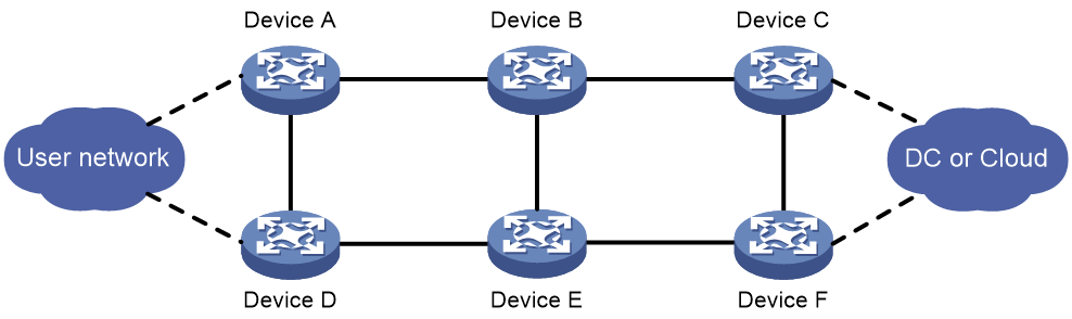
Packet loss after FRR switchback
Symptom
As shown in Figure 8, the backbone network uses BGP as the control plane protocol to carry routing information. Device A can forward user traffic to the data center or cloud network through multiple paths. When Device C fails, Device A detects the failure with BFD and FRR is triggered. As a result, traffic is steered to Device F. After Device C recovers and FRR switches traffic back to the primary path (traversing Device C), packet loss occurs.
Common causes
After Device C recovers, it sends a route update to Device A. Upon receiving the update, Device A switches traffic to the primary path (traversing Device C). However, at this time, Device C has not finished updating its FIB, which causes packet loss.
Analysis
Figure 9 shows the troubleshooting flowchart:
Figure 9 Troubleshooting flowchart
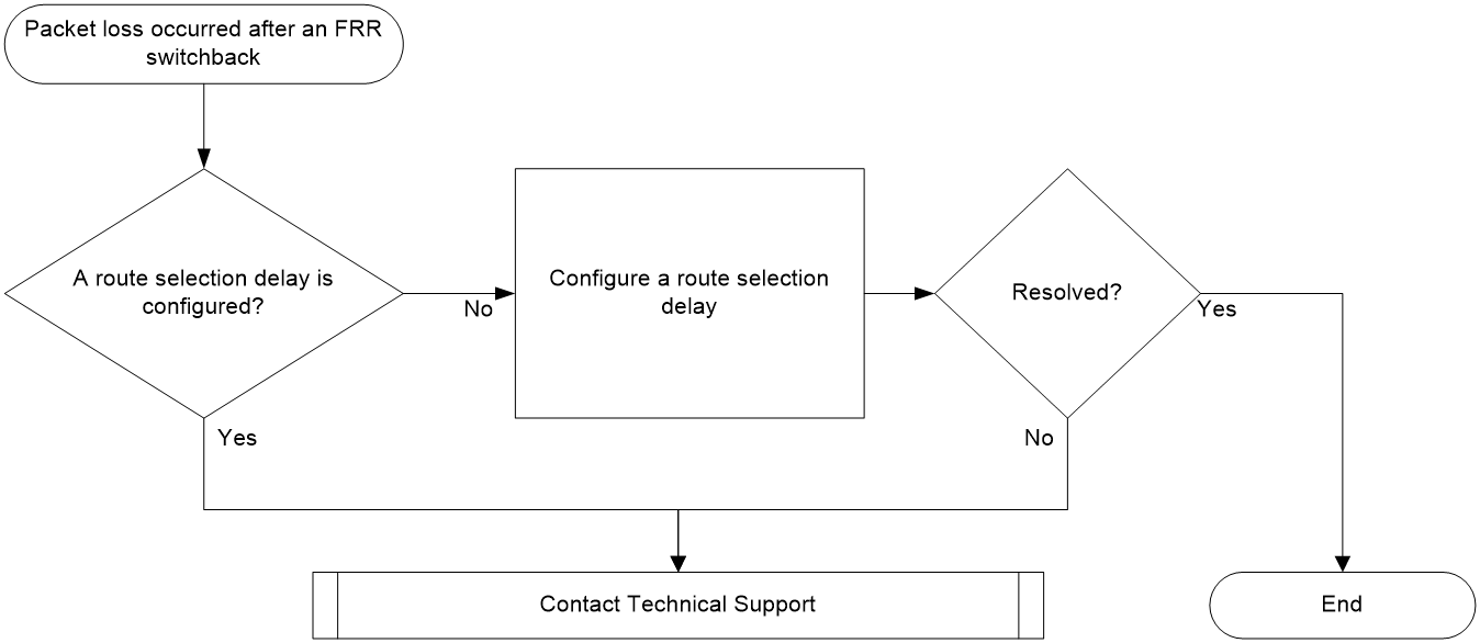
Solution
1. On Device A, execute the route-select delay delay-value command to configure a route selection delay in the BGP address family where FRR is enabled. After that, Device A performs route selection only after the route selection delay elapses. This practice ensures that all devices along the forwarding path can finish updating their forwarding entries before a path switch.
2. If the issue persists, collect the following information and contact Technical Support:
¡ Results of each step.
¡ The configuration file, log messages, and alarm messages.
Related alarm and log messages
Alarm messages
N/A
Log messages
N/A