- Table of Contents
-
- 07-IP Multicast Configuration Guide
- 00-Preface
- 01-Multicast overview
- 02-IGMP snooping configuration
- 03-PIM snooping configuration
- 04-Multicast VLAN configuration
- 05-Multicast routing and forwarding configuration
- 06-IGMP configuration
- 07-PIM configuration
- 08-MSDP configuration
- 09-Multicast VPN overview
- 10-MDT-based MVPN configuration
- 11-RSVP-TE-based MVPN configuration
- 12-mLDP-based MVPN configuration
- 13-BIER-based MVPN configuration
- 14-MVPN extranet configuration
- 15-MLD snooping configuration
- 16-IPv6 PIM snooping configuration
- 17-IPv6 multicast VLAN configuration
- 18-IPv6 multicast routing and forwarding configuration
- 19-MLD configuration
- 20-IPv6 PIM configuration
- Related Documents
-
| Title | Size | Download |
|---|---|---|
| 14-MVPN extranet configuration | 218.57 KB |
Source-PE-based MVPN extranet option
Receiver-PE-based MVPN extranet option
Configuring an MVPN extranet RPF selection policy
About configuring MVPN extranet RPF selection policies
Restrictions and guidelines for configuring MVPN extranet RPF selection policies
Prerequisites for configuring MVPN extranet RPF selection policies
Configuring an IPv4 MVPN extranet RPF selection policy
MVPN extranet configuration examples
Example: Configuring receiver-PE-based MVPN extranet
Configuring MVPN extranet
MVPN extranet overview
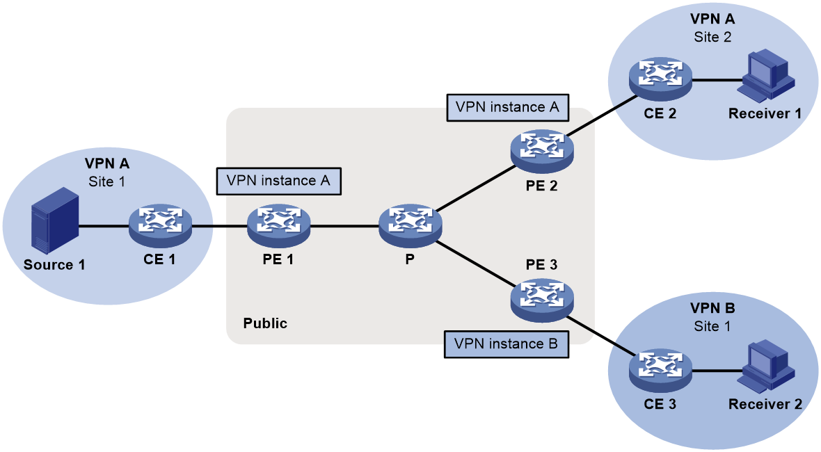
MVPN extranet implements inter-VPN multicast traffic transmission. In MVPN extranet, the multicast source and receivers are in different VPNs. In actual application, the MVPN extranet solution ensures that the service provider in a VPN provides multicast services for users in other VPNs.
The following terms are used in the MVPN extranet solution:
· Source VPN instance—VPN instance to which the multicast source belongs.
· Receiver VPN instance—VPN instance to which the multicast receiver belongs.
· Source PE—PE directly connected to the multicast source.
· Receiver PE—PE directly connected to multicast receivers.
As shown in Figure 1, multicast source Source 1 is in Site 1 of VPN A. Receiver 1 and Receiver 2 are located in Site 2 of VPN A and Site 1 of VPN B, respectively. MVPN enables Receiver 1 to receive multicast data from Source 1, and MVPN extranet enables Receiver 2 to receive multicast data from Source 1.
The MVPN extranet solution can be implemented through the source-PE-based MVPN extranet option or the receiver-PE-based MVPN extranet option.
Source-PE-based MVPN extranet option
To use this option, create a receiver VPN instance on the source PE and specify a default group for this VPN instance. The default group for the receiver VPN instance must be the same as the default group specified on other PEs in this VPN instance.
This option is available only in MDT-based MVPN.
As shown in Figure 2, perform the following tasks:
1. For multicast traffic transmission from Site 1 to Site 2, configure MVPN for VPN A on PE 1 and PE 2.
2. For multicast traffic transmission from Site 1 to Site 3, create VPN B and configure MVPN for VPN B on PE 1.
3. Configure an MVPN extranet RPF selection policy for VPN B on PE 1.
Figure 2 Source-PE-based MVPN extranet option
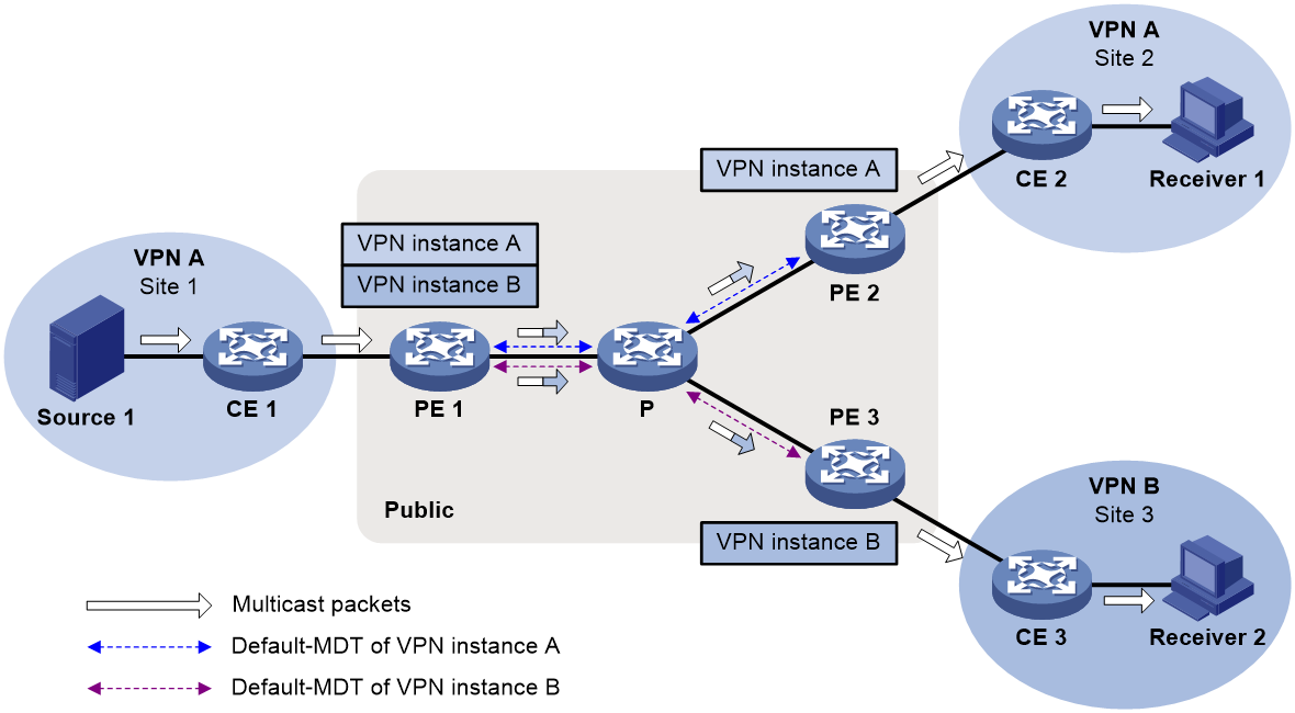
When Receiver 2 in VPN B joins the multicast group that matches the policy, multicast packets from Source 1 are transmitted as follows:
1. PE 1 replicates and encapsulates the packets for VPN A and VPN B and forwards them.
2. The packets travel along default MDTs of VPN A and VPN B and arrive at PE 2 and PE 3.
3. PE 2 and PE 3 decapsulate and forward the packets to receivers.
Receiver-PE-based MVPN extranet option
To use this option, create a source VPN instance on the receiver PE and specifies a default group for this VPN instance. The default group for the source VPN instance must be the same as the default group specified on other PEs in this VPN instance.
This option is available in MDT-based MVPN, RSVP-TE-based MVPN, and mLDP-based MVPN. This example uses MDT-based MVPN.
As shown in Figure 3, configure PEs as follows:
1. For multicast traffic transmission from Site 1 to Site 2, configure MVPN for VPN A on PE 1 and PE 2.
2. For multicast traffic transmission from Site 1 to Site 3, create VPN A and configure MVPN for VPN A on PE 3.
3. Configure an MVPN extranet RPF selection policy for VPN B on PE 3.
Figure 3 Receiver-PE-based MVPN extranet option
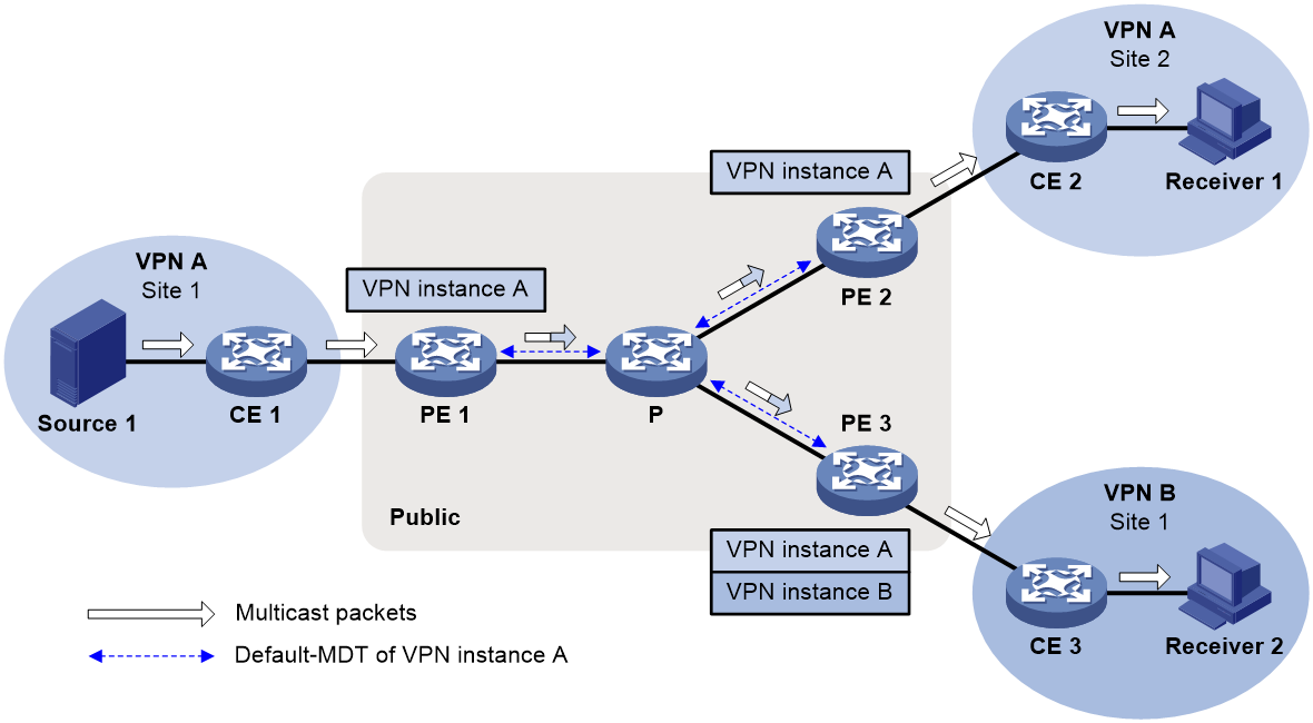
When Receiver 2 in VPN B joins the multicast group that matches the RPF selection policy, multicast packets from Source 1 are encapsulated on PE 1 and transmitted along the default MDT.
1. When the packets arrive at PE 2, PE 2 decapsulates the packets and forwards them to Receiver 1.
2. When the packets arrive at PE 3, PE 3 decapsulates the packets and forwards them to Receiver 2 based on the MVPN extranet RPF selection policy.
Configuring an MVPN extranet RPF selection policy
About configuring MVPN extranet RPF selection policies
MVPN extranet RPF routing policies are used for multicast transmission when multicast sources and receivers are located in different VPNs.
Restrictions and guidelines for configuring MVPN extranet RPF selection policies
The PIM modes in the source VPN instance and the receiver VPN instance must be the same. Only PIM-SM and PIM-SSM are supported.
Multicast packets can only be forwarded between two VPNs. The receiver VPN instance cannot also be the source VPN instance.
In PIM-SM mode, you can configure only one RPF selection policy for a multicast group in a VPN instance.
If an MVPN extranet RPF selection policy is configured in the receiver VPN instance, the multicast traffic of the source group specified in the extranet RPF selection policy will be interrupted.
To implement source-specific RPF selection in MVPN extranet, you must configure two MVPN extranet RPF routing policies as follows:
· In one policy, specify the address of the RP designated to the multicast group that requires inter-VPN multicast communication as the source address.
· In the other policy, specify the multicast source in the source VPN instance as the source address.
To implement source-and-group-specific RPF selection in MVPN extranet, you must configure two MVPN extranet RPF routing policies as follows:
· In one policy, specify the address of the RP designated to the multicast group as the source address, and specify the multicast group.
· In the other policy, specify the multicast source in the source VPN instance as the source address, and specify the multicast group.
· Make sure the multicast groups in the two policies are the same to avoid inter-VPN multicast transmission failure.
Only common Layer 3 multicast and MDT-based MVPN support the source-PE-based MVPN extranet option. Common Layer 3 multicast, MDT-based MVPN, RSVP-TE-based MVPN, mLDP-based MVPN, and BIER-based MVPN support the receiver-PE-based MVPN extranet option.
For the source-PE-based MVPN extranet option, if PIM-SM mode is used, the RP of the receiver VPN instance must be configured on the multicast source-side device.
Prerequisites for configuring MVPN extranet RPF selection policies
For the source-PE-based MVPN extranet option, configure MDT-based MVPN first. For more information, see "Configuring MDT-based MVPN."
For the receiver-PE-based MVPN extranet option, configure MDT-based, RSVP-TE-based, or mLDP-based MVPN first. For more information, see "Configuring MDT-based MVPN", "Configuring RSVP-TE-based MVPN", "Configuring mLDP-based MVPN", and "Configuring BIER-based MVPN."
Configuring an IPv4 MVPN extranet RPF selection policy
1. Enter system view.
system-view
2. Enter MRIB view.
multicast routing [ vpn-instance vpn-instance-name ]
3. Configure an IPv4 MVPN extranet RPF selection policy.
multicast extranet select-rpf [ vpn-instance vpn-instance-name ] { source source-address { mask | mask-length } | group group-address { mask | mask-length } } *
By default, no IPv4 MVPN extranet RPF selection policies are configured.
MVPN extranet configuration examples
Example: Configuring receiver-PE-based MVPN extranet
Network configuration
As shown in Figure 4, configure MVPN extranet to meet the following requirements:
|
Item |
Network configuration |
|
Multicast sources and receivers |
· In VPN instance a, S 1 is a multicast source. · In VPN instance b, R 1 is a receiver. · For VPN instance a, the default group is 239.1.1.1, and the data group range is 225.2.2.0 to 225.2.2.15. |
|
VPN instances to which PE interfaces belong |
· PE 1: Ten-GigabitEthernet0/0/15 belongs to VPN instance a. Ten-GigabitEthernet0/0/16 and Loopback 0 belong to the public network instance. · PE 2: Ten-GigabitEthernet0/0/16 belongs to VPN instance b. Ten-GigabitEthernet0/0/15 and Loopback 0 belong to the public network instance. |
|
Unicast routing protocols and MPLS |
· Configure OSPF on the public network and configure RIP between PEs and CEs. · Establish BGP peer connections between PE 1 and PE 2 on their respective Loopback 0. · Configure MPLS on the public network. |
|
IP multicast routing |
· Enable IP multicast routing on the P device. · Enable IP multicast routing for the public network on PE 1 and PE 2. · Enable IP multicast routing for VPN instance a on PE 1. · Enable IP multicast routing for VPN instance b on PE 2. · Enable IP multicast routing on CE 1 and CE 2. |
|
IGMPv2 |
Enable IGMPv2 on Ten-GigabitEthernet0/0/16 of CE 2. |
|
PIM-SM |
Enable PIM-SM on the public network and for VPN instances a and b: · Enable PIM-SM on all interfaces of the P device. · Enable PIM-SM on all public and private network interfaces of PE 1 and PE 2. · Enable PIM-SM on all interfaces that do not have attached receiver hosts on CE 1 and CE 2. · Configure Loopback 0 of the P device as a C-BSR and a C-RP for the public network to provide services for all multicast groups. · Configure Loopback 1 of CE 1 as a C-BSR and a C-RP for VPN instance a to provide services for all multicast groups. · Configure Loopback 1 of PE 2 as a C-BSR and a C-RP for VPN instance b to provide services for all multicast groups. |
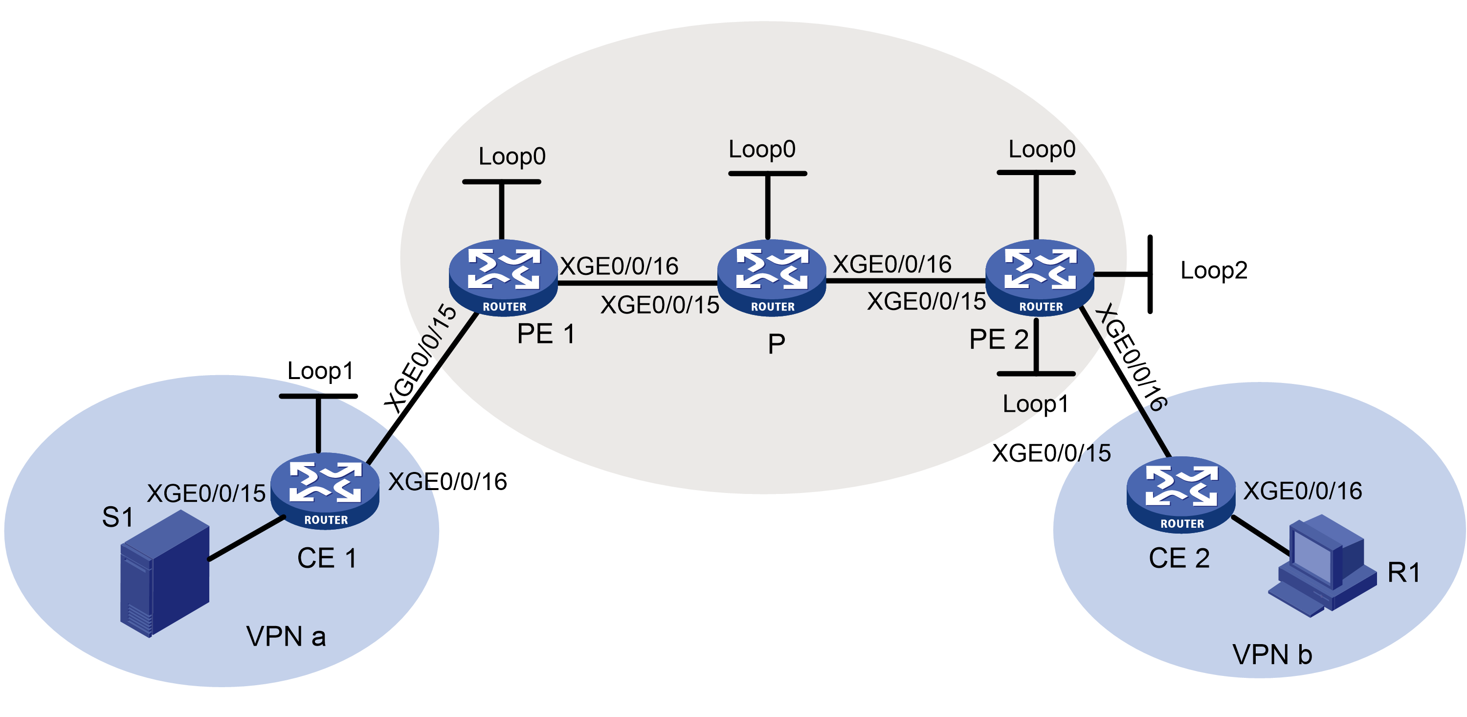
Table 1 Interface and IP address assignment
|
Device |
Interface |
IP address |
Device |
Interface |
IP address |
|
S 1 |
— |
10.110.7.2/24 |
PE 2 |
XGE0/0/15 |
192.168.7.1/24 |
|
R 1 |
— |
10.110.11.2/24 |
PE 2 |
XGE0/0/16 |
10.110.3.2/24 |
|
P |
XGE0/0/15 |
192.168.6.1/24 |
PE 2 |
Loop0 |
1.1.1.2/32 |
|
P |
XGE0/0/16 |
192.168.7.2/24 |
PE 2 |
Loop1 |
20.20.20.20/32 |
|
P |
Loop0 |
2.2.2.2/32 |
PE 2 |
Loop2 |
100.100.100.100/32 |
|
PE 1 |
XGE0/0/15 |
10.110.2.1/24 |
CE 1 |
XGE0/0/15 |
10.110.7.1/24 |
|
PE 1 |
XGE0/0/16 |
192.168.6.2/24 |
CE 1 |
XGE0/0/16 |
10.110.2.2/24 |
|
PE 1 |
Loop0 |
1.1.1.1/32 |
CE 1 |
Loop1 |
11.11.11.11/32 |
|
|
|
|
CE 2 |
XGE0/0/15 |
10.110.3.1/24 |
|
|
|
|
CE 2 |
XGE0/0/16 |
10.110.11.1/24 |
Procedure
1. Configure PE 1:
# Configure a global router ID, and enable IP multicast routing on the public network.
<PE1> system-view
[PE1] router id 1.1.1.1
[PE1] multicast routing
[PE1-mrib] quit
# Configure an LSR ID, and enable LDP globally.
[PE1] mpls lsr-id 1.1.1.1
[PE1] mpls ldp
[PE1-ldp] quit
# Assign an IP address to Loopback 0, and enable PIM-SM on the interface.
[PE1] interface loopback 0
[PE1-LoopBack0] ip address 1.1.1.1 32
[PE1-LoopBack0] pim sm
[PE1-LoopBack0] quit
# Create a VPN instance named a, and configure an RD and route targets for the VPN instance.
[PE1] ip vpn-instance a
[PE1-vpn-instance-a] route-distinguisher 100:1
[PE1-vpn-instance-a] vpn-target 100:1 export-extcommunity
[PE1-vpn-instance-a] vpn-target 100:1 import-extcommunity
[PE1-vpn-instance-a] quit
# Enable IP multicast routing for VPN instance a.
[PE1] multicast routing vpn-instance a
[PE1-mrib-a] quit
# Create an MDT-based MVPN for VPN instance a.
[PE1] multicast-vpn vpn-instance a mode mdt
# Create an MVPN IPv4 address family for VPN instance a.
[PE1-mvpn-vpn-instance-a] address-family ipv4
# Specify the default group, the MVPN source interface, and the data group range for VPN instance a.
[PE1-mvpn-vpn-instance-a-ipv4] default-group 239.1.1.1
[PE1-mvpn-vpn-instance-a-ipv4] source loopback 0
[PE1-mvpn-vpn-instance-a-ipv4] data-group 225.2.2.0 28
[PE1-mvpn-vpn-instance-a-ipv4] quit
[PE1-mvpn-vpn-instance-a] quit
# Assign an IP address to Ten-GigabitEthernet 0/0/16, and enable PIM-SM, MPLS, and IPv4 LDP on the interface.
[PE1] interface ten-gigabitethernet 0/0/16
[PE1-Ten-GigabitEthernet0/0/16] ip address 192.168.6.2 24
[PE1-Ten-GigabitEthernet0/0/16] pim sm
[PE1-Ten-GigabitEthernet0/0/16] mpls enable
[PE1-Ten-GigabitEthernet0/0/16] mpls ldp enable
[PE1-Ten-GigabitEthernet0/0/16] quit
# Associate Ten-GigabitEthernet 0/0/15 with VPN instance a, assign an IP address to the interface and enable PIM-SM on the interface.
[PE1] interface ten-gigabitethernet 0/0/15
[PE1-Ten-GigabitEthernet0/0/15] ip binding vpn-instance a
[PE1-Ten-GigabitEthernet0/0/15] ip address 10.110.2.1 24
[PE1-Ten-GigabitEthernet0/0/15] pim sm
[PE1-Ten-GigabitEthernet0/0/15] quit
# Configure BGP.
[PE1] bgp 100
[PE1-bgp-default] group vpn-g internal
[PE1-bgp-default] peer vpn-g connect-interface loopback 0
[PE1-bgp-default] peer 1.1.1.2 group vpn-g
[PE1–bgp-default] ip vpn-instance a
[PE1-bgp-default-a] address-family ipv4
[PE1-bgp-default-ipv4-a] import-route rip 2
[PE1-bgp-default-ipv4-a] import-route direct
[PE1-bgp-default-ipv4-a] quit
[PE1-bgp-default-a] quit
[PE1–bgp-default] address-family vpnv4
[PE1–bgp-default-vpnv4] peer vpn-g enable
[PE2–bgp-default-vpnv4] quit
[PE1–bgp-default] address-family ipv4 mdt
[PE1–bgp-default-mdt] peer vpn-g enable
[PE1–bgp-default-mdt] quit
[PE1–bgp-default] quit
# Configure OSPF.
[PE1] ospf 1
[PE1-ospf-1] area 0.0.0.0
[PE1-ospf-1-area-0.0.0.0] network 1.1.1.1 0.0.0.0
[PE1-ospf-1-area-0.0.0.0] network 192.168.6.0 0.0.0.255
[PE1-ospf-1-area-0.0.0.0] quit
[PE1-ospf-1] quit
# Configure RIP.
[PE1] rip 2 vpn-instance a
[PE1-rip-2] network 10.110.2.0 0.0.0.255
[PE1-rip-2] import-route bgp
[PE1-rip-2] quit
2. Configure PE 2:
# Configure a global router ID, and enable IP multicast routing on the public network.
<PE2> system-view
[PE2] router id 1.1.1.2
[PE2] multicast routing
[PE2-mrib] quit
# Configure an LSR ID, and enable LDP globally.
[PE2] mpls lsr-id 1.1.1.2
[PE2] mpls ldp
[PE2-ldp] quit
# Assign an IP address to Loopback 0, and enable PIM-SM on the interface.
[PE2] interface loopback 0
[PE2-LoopBack0] ip address 1.1.1.2 32
[PE2-LoopBack0] pim sm
[PE2-LoopBack0] quit
# Create a VPN instance named a, and configure an RD and route targets for the VPN instance.
[PE2] ip vpn-instance a
[PE2-vpn-instance-a] route-distinguisher 100:1
[PE2-vpn-instance-a] vpn-target 100:1 export-extcommunity
[PE2-vpn-instance-a] vpn-target 100:1 import-extcommunity
[PE2-vpn-instance-a] quit
# Enable IP multicast routing for VPN instance a.
[PE2] multicast routing vpn-instance a
[PE2-mrib-a] quit
# Create an MDT-based MVPN for VPN instance a.
[PE2] multicast-vpn vpn-instance a mode mdt
# Create an MVPN IPv4 address family for VPN instance a.
[PE2-mvpn-vpn-instance-a] address-family ipv4
# Specify the default group, the MVPN source interface, and the data group range for VPN instance a.
[PE2-mvpn-vpn-instance-a-ipv4] default-group 239.1.1.1
[PE2-mvpn-vpn-instance-a-ipv4] source loopback 0
[PE2-mvpn-vpn-instance-a-ipv4] data-group 225.2.2.0 28
[PE2-mvpn-vpn-instance-a-ipv4] quit
[PE2-mvpn-vpn-instance-a] quit
# Create a VPN instance named b.
[PE2] ip vpn-instance b
[PE2-vpn-instance-b] quit
# Enable IP multicast routing for VPN instance b.
[PE2] multicast routing vpn-instance b
# Configure IPv4 MVPN extranet RPF selection policies.
[PE2-mrib-b] multicast extranet select-rpf vpn-instance a source 10.110.7.2 32 group 226.1.1.0 24
[PE2-mrib-b] multicast extranet select-rpf vpn-instance a source 20.20.20.20 32 group 226.1.1.0 24
[PE2-mrib-b] quit
# Assign an IP address to Ten-GigabitEthernet 0/0/15, and enable PIM-SM, MPLS, and IPv4 LDP on the interface.
[PE2] interface ten-gigabitethernet 0/0/15
[PE2-Ten-GigabitEthernet0/0/15] ip address 192.168.7.1 24
[PE2-Ten-GigabitEthernet0/0/15] pim sm
[PE2-Ten-GigabitEthernet0/0/15] mpls enable
[PE2-Ten-GigabitEthernet0/0/15] mpls ldp enable
[PE2-Ten-GigabitEthernet0/0/15] quit
# Associate Ten-GigabitEthernet 0/0/16 with VPN instance b, assign an IP address to the interface, and enable PIM-SM on the interface.
[PE2] interface ten-gigabitethernet 0/0/16
[PE2-Ten-GigabitEthernet0/0/16] ip binding vpn-instance b
[PE2-Ten-GigabitEthernet0/0/16] ip address 10.110.3.2 24
[PE2-Ten-GigabitEthernet0/0/16] pim sm
[PE2-Ten-GigabitEthernet0/0/16] quit
# Associate Loopback 1 with VPN instance b, assign an IP address to the interface, and enable PIM-SM on the interface.
[PE2] interface loopback 1
[PE2-LoopBack1] ip binding vpn-instance b
[PE2-LoopBack1] ip address 20.20.20.20 32
[PE2-LoopBack1] pim sm
[PE2-LoopBack1] quit
# Configure Loopback 1 as a C-BSR and a C-RP for VPN instance b.
[PE2] pim vpn-instance b
[PE2-pim-b] c-bsr 20.20.20.20
[PE2-pim-b] c-rp 20.20.20.20
[PE2-pim-b] quit
# Associate Loopback 2 with VPN instance a, assign an IP address to the interface, and enable PIM-SM on the interface.
[PE2] interface loopback 2
[PE2-LoopBack2] ip binding vpn-instance a
[PE2-LoopBack2] ip address 100.100.100.100 32
[PE2-LoopBack2] pim sm
[PE2-LoopBack2] quit
# Configure BGP.
[PE2] bgp 100
[PE2-bgp-default] group vpn-g internal
[PE2-bgp-default] peer vpn-g connect-interface loopback 0
[PE2-bgp-default] peer 1.1.1.1 group vpn-g
[PE2–bgp-default] ip vpn-instance a
[PE2-bgp-default-a] address-family ipv4
[PE2-bgp-default-ipv4-a] import-route direct
[PE2-bgp-default-ipv4-a] quit
[PE2-bgp-default-a] quit
[PE2–bgp-default] address-family vpnv4
[PE2–bgp-default-vpnv4] peer vpn-g enable
[PE2–bgp-default-vpnv4] quit
[PE2–bgp-default] address-family ipv4 mdt
[PE2–bgp-default-mdt] peer vpn-g enable
[PE2–bgp-default-mdt] quit
[PE2–bgp-default] quit
# Configure OSPF.
[PE2] ospf 1
[PE2-ospf-1] area 0.0.0.0
[PE2-ospf-1-area-0.0.0.0] network 1.1.1.2 0.0.0.0
[PE2-ospf-1-area-0.0.0.0] network 192.168.7.0 0.0.0.255
[PE2-ospf-1-area-0.0.0.0] quit
[PE2-ospf-1] quit
# Configure RIP.
[PE2] rip 3 vpn-instance b
[PE2-rip-3] network 10.110.3.0 0.0.0.255
[PE2-rip-3] network 20.20.20.20 0.0.0.0
[PE2-rip-3] import-route bgp
[PE2-rip-3] quit
3. Configure the P device:
# Enable IP multicast routing on the public network.
<P> system-view
[P] multicast routing
[P-mrib] quit
# Configure an LSR ID, and enable LDP globally.
[P] mpls lsr-id 2.2.2.2
[P] mpls ldp
[P-ldp] quit
# Assign an IP address to Ten-GigabitEthernet 0/0/15, and enable PIM-SM, MPLS, and IPv4 LDP on the interface.
[P] interface ten-gigabitethernet 0/0/15
[P-Ten-GigabitEthernet0/0/15] ip address 192.168.6.1 24
[P-Ten-GigabitEthernet0/0/15] pim sm
[P-Ten-GigabitEthernet0/0/15] mpls enable
[P-Ten-GigabitEthernet0/0/15] mpls ldp enable
[P-Ten-GigabitEthernet0/0/15] quit
# Assign an IP address to Ten-GigabitEthernet 0/0/16, and enable PIM-SM, MPLS, and IPv4 LDP on the interface.
[P] interface ten-gigabitethernet 0/0/16
[P-Ten-GigabitEthernet0/0/16] ip address 192.168.7.2 24
[P-Ten-GigabitEthernet0/0/16] pim sm
[P-Ten-GigabitEthernet0/0/16] mpls enable
[P-Ten-GigabitEthernet0/0/16] mpls ldp enable
[P-Ten-GigabitEthernet0/0/16] quit
# Assign an IP address to Loopback 0, and enable PIM-SM on the interface.
[P] interface loopback 0
[P-LoopBack0] ip address 2.2.2.2 32
[P-LoopBack0] pim sm
[P-LoopBack0] quit
# Configure Loopback 0 as a C-BSR and a C-RP for the public network.
[P] pim
[P-pim] c-bsr 2.2.2.2
[P-pim] c-rp 2.2.2.2
[P-pim] quit
# Configure OSPF.
[P] ospf 1
[P-ospf-1] area 0.0.0.0
[P-ospf-1-area-0.0.0.0] network 2.2.2.2 0.0.0.0
[P-ospf-1-area-0.0.0.0] network 192.168.6.0 0.0.0.255
[P-ospf-1-area-0.0.0.0] network 192.168.7.0 0.0.0.255
[P-ospf-1-area-0.0.0.0] quit
4. Configure CE 1:
# Enable IP multicast routing.
<CE1> system-view
[CE1] multicast routing
[CE1-mrib] quit
# Assign an IP address to Ten-GigabitEthernet 0/0/15, and enable PIM-SM on the interface.
[CE1] interface ten-gigabitethernet 0/0/15
[CE1-Ten-GigabitEthernet0/0/15] ip address 10.110.7.1 24
[CE1-Ten-GigabitEthernet0/0/15] pim sm
[CE1-Ten-GigabitEthernet0/0/15] quit
# Assign an IP address to Ten-GigabitEthernet 0/0/16, and enable PIM-SM on the interface.
[CE1] interface ten-gigabitethernet 0/0/16
[CE1-Ten-GigabitEthernet0/0/16] ip address 10.110.2.2 24
[CE1-Ten-GigabitEthernet0/0/16] pim sm
[CE1-Ten-GigabitEthernet0/0/16] quit
# Assign an IP address to Loopback 1, and enable PIM-SM on the interface.
[CE1] interface loopback 1
[CE1-LoopBack1] ip address 11.11.11.11 32
[CE1-LoopBack1] pim sm
[CE1-LoopBack1] quit
# Configure Loopback 1 as a C-BSR and a C-RP for VPN instance a.
[CE1] pim
[CE1-pim] c-bsr 11.11.11.11
[CE1-pim] c-rp 11.11.11.11
[CE1-pim] quit
# Configure RIP.
[CE1] rip 2
[CE1-rip-2] network 10.110.2.0 0.0.0.255
[CE1-rip-2] network 10.110.7.0 0.0.0.255
[CE1-rip-2] network 11.11.11.11 0.0.0.0
[CE1-rip-2] quit
5. Configure CE 2:
# Enable IP multicast routing.
<CE2> system-view
[CE2] multicast routing
[CE2-mrib] quit
# Assign an IP address to Ten-GigabitEthernet 0/0/15, and enable IGMP on the interface.
[CE2] interface ten-gigabitethernet 0/0/15
[CE2-Ten-GigabitEthernet0/0/15] ip address 10.110.3.1 24
[CE2-Ten-GigabitEthernet0/0/15] pim sm
[CE2-Ten-GigabitEthernet0/0/15] quit
# Assign an IP address to Ten-GigabitEthernet 0/0/16, and enable PIM-SM on the interface.
[CE2] interface ten-gigabitethernet 0/0/16
[CE2-Ten-GigabitEthernet0/0/16] ip address 10.110.11.1 24
[CE2-Ten-GigabitEthernet0/0/16] igmp enable
[CE2-Ten-GigabitEthernet0/0/16] quit
# Configure RIP.
[CE2] rip 3
[CE2-rip-3] network 10.110.3.0 0.0.0.255
[CE2-rip-3] network 10.110.11.0 0.0.0.255
[CE2-rip-3] quit
Verifying the configuration
# Display information about the local default group for IPv4 multicast transmission in each VPN instance on PE 1.
[PE1] display multicast-vpn default-group local
MVPN local default-group information:
Group address Source address Interface VPN instance
239.1.1.1 1.1.1.1 MTunnel0 a
# Display information about the local default group for IPv4 multicast transmission in each VPN instance on PE 2.
[PE2] display multicast-vpn default-group local
MVPN local default-group information:
Group address Source address Interface VPN instance
239.1.1.1 1.1.1.2 MTunnel0 a
# Display PIM routing entries for MVPN extranet of VPN instance a on PE 2.
[PE2] display pim vpn-instance a routing-table
Total 1 (*, G) entries; 1 (S, G) entries
(*, 226.1.1.1)
RP: 11.11.11.11
Protocol: pim-sm, Flag: WC
UpTime: 07:06:11
Upstream interface: MTunnel0
Upstream neighbor: 1.1.1.1
RPF prime neighbor: 1.1.1.1
Downstream interface information:
Total number of downstream interfaces: 1
1: Extranet (VPN: b)
Protocol: MD, UpTime: 01:12:52, Expires: -
(10.110.7.2, 226.1.1.1)
RP: 11.11.11.11
Protocol: pim-sm, Flag: SPT ACT RQ
UpTime: 07:06:10
Upstream interface: MTunnel0
Upstream neighbor: 1.1.1.1
RPF prime neighbor: 1.1.1.1
Downstream interface information:
Total number of downstream interfaces: 1
1: Extranet (VPN: b)
Protocol: MD, UpTime: 01:12:52, Expires: -
# Display PIM routing entries for MVPN extranet of VPN instance b on PE 2.
[PE2] display pim vpn-instance b routing-table
Total 1 (*, G) entries; 1 (S, G) entries
(*, 226.1.1.1)
RP: 20.20.20.20
Protocol: pim-sm, Flag: WC
UpTime: 07:06:11
Upstream interface: Extranet (VPN: a)
Upstream neighbor: 127.0.0.1
RPF prime neighbor: 127.0.0.1
Downstream interface information:
Total number of downstream interfaces: 1
1: Ten-GigabitEthernet0/0/16
Protocol: igmp, UpTime: 01:12:52, Expires: -
(10.110.7.2, 226.1.1.1)
RP: 20.20.20.20
Protocol: pim-sm, Flag: SPT ACT 2MVPN
UpTime: 07:06:10
Upstream interface: Extranet (VPN: a)
Upstream neighbor: 127.0.0.1
RPF prime neighbor: 127.0.0.1
Downstream interface information:
Total number of downstream interfaces: 1
1:
