- Table of Contents
-
- 07-IP Multicast Configuration Guide
- 00-Preface
- 01-Multicast overview
- 02-IGMP snooping configuration
- 03-PIM snooping configuration
- 04-Multicast VLAN configuration
- 05-Multicast routing and forwarding configuration
- 06-IGMP configuration
- 07-PIM configuration
- 08-MSDP configuration
- 09-Multicast VPN overview
- 10-MDT-based MVPN configuration
- 11-RSVP-TE-based MVPN configuration
- 12-mLDP-based MVPN configuration
- 13-BIER-based MVPN configuration
- 14-MVPN extranet configuration
- 15-MLD snooping configuration
- 16-IPv6 PIM snooping configuration
- 17-IPv6 multicast VLAN configuration
- 18-IPv6 multicast routing and forwarding configuration
- 19-MLD configuration
- 20-IPv6 PIM configuration
- Related Documents
-
| Title | Size | Download |
|---|---|---|
| 11-RSVP-TE-based MVPN configuration | 267.60 KB |
Configuring RSVP-TE-based MVPN
Inclusive tunnel establishment
Selective tunnel establishment and tunnel switchover
RSVP-TE-based MVPN tasks at a glance
Configuring RSVP-TE-based MVPN
Prerequisites for configuring RSVP-TE-based MVPN
Enabling IP multicast routing for a VPN instance
Configuring BGP IPv4 MVPN route exchange
Creating an RSVP-TE-based MVPN instance
Creating an MVPN IPv4 address family
Specifying the MVPN source interface
Enabling inclusive tunnel creation
Enabling selective tunnel creation
Setting the tunnel switchover delay
Display and maintenance commands for RSVP-TE-based MVPN
Configuring RSVP-TE-based MVPN
RSVP-TE-based MVPN overview
Basic concepts
This section introduces the following concepts in RSVP-TE-based MVPN:
· MVPN—An MVPN logically defines the transmission boundary of the multicast traffic of a VPN over the public network. It also physically identifies all the PEs that support that VPN instance on the public network. Different VPN instances correspond to different MVPNs. All PEs in an MVPN are MVPN peers.
· Inclusive tunnel—Transmits all multicast packets (including multicast protocol packets and multicast data packets of all multicast groups) for an MVPN. Only one inclusive tunnel can be established between two PEs in the MVPN. A PE encapsulates multicast data packets and PIM BSMs of an MVPN into public network multicast data packets and sends them over the public network through the inclusive tunnel.
· Selective tunnel—Transmits multicast packets of one or more multicast groups for an MVPN. Multiple selective tunnels can be established between two PEs in the MVPN.
RSVP-TE-based MVPN operation
Packet transmission on the public network is transparent for a VPN instance. Each two PEs establish IBGP neighbor relationship and use BGP to advertise routing information for MVPN. The following types of routes are used to create RSVP-TE tunnels for an MVPN:
· Intra-AS I-PMSI A-D route—PEs use this type of route to establish inclusive tunnels.
· S-PMSI A-D route—The multicast source-side PE sends this type of route to receiver-side PEs for tunnel switchover when selective tunnel creation is enabled and the tunnel creation criterion is met.
· Leaf A-D route—A receiver-side PE that has attached receivers replies with a Leaf A-D route when it receives an S-PMSI A-D route from the multicast source-side PE. RSVP-TE creates selective tunnels between receiver-side PEs and the multicast-side PE based on the neighbor information contained in Leaf A-D routes.
· Source Active A-D route—The multicast source-side PE sends this type of route to receiver-side PEs to advertise the location of the multicast source.
· C-multicast route—After receiving the Source Active A-D route from the multicast source-side PE, a receiver-side PE replies with a C-Multicast route to request the multicast source-side PE to send multicast data.
Multicast packets of a VPN instance are seamlessly transmitted from a CE to the inclusive tunnel on the PE based on the PIM routing table. These packets are then transmitted to the remote PE through the inclusive tunnel. After receiving the packets, the remote PE decapsulates the packets to get the original private packets. The multicast source-side PE creates selective tunnels when multicast traffic that meets the tunnel switchover criterion arrives.
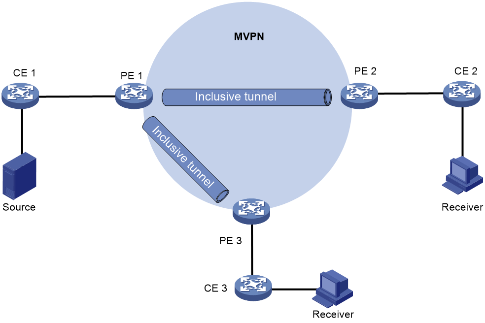
Inclusive tunnel establishment
As shown in Figure 1, the private network runs PIM, and the public network uses MPLS backbone. The inclusive tunnels are established as follows:
1. PE 1, PE 2, and PE 3 mutually establish IBGP neighbor relationship and exchange routing information to get the public network address of each PE.
2. PE 1 (source of the tunnel) sends an Intra-AS I-PMSI A-D route to PE 2 and PE 3 (destination of the tunnel) to advertise the inclusive tunnel information.
3. PE 2 and PE 3 each establish an inclusive tunnel with PE 1. The inclusive tunnel on the public network does not rely on PIM running on the private network.
Figure 1 Inclusive tunnel establishment
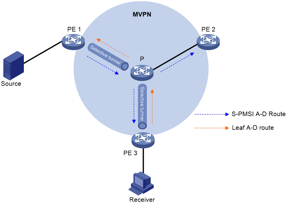
Selective tunnel establishment and tunnel switchover
As shown in Figure 2, selective tunnels are established and switched as follows:
1. After multicast source-side PE 1 receives a multicast packet of the (S, G) entry that meets the tunnel switchover criterion, it sends an S-PMSI A-D route to PE 2 and PE 3.
2. PE 2 does not send a response because it has no receivers of the (S,G) entry attached.
3. PE 3 replies with a Leaf A-D route because it is attached to a receiver of the entry.
4. PE 1 and PE 3 establish a selective tunnel.
5. Subsequent multicast packets of the (S,G) entry that enters the public network from PE 1 are switched over to the selective tunnel from the inclusive tunnel.
Figure 2 Selective tunnel establishment
RSVP-TE-based MVPN tasks at a glance
To configure RSVP-TE-based MVPN, perform the following tasks on PEs:
1. Enabling IP multicast routing for a VPN instance
2. Configuring BGP IPv4 MVPN route exchange
4. Creating an RSVP-TE-based MVPN instance
5. Creating an MVPN IPv4 address family
6. Specifying the MVPN source interface
7. Enabling inclusive tunnel creation
8. (Optional.) Enabling selective tunnel creation
9. (Optional.) Setting the tunnel switchover delay
Configuring RSVP-TE-based MVPN
Prerequisites for configuring RSVP-TE-based MVPN
Before you configure RSVP-TE-based MVPN, complete the following tasks:
· Configure a unicast routing protocol on the public network.
· Configure MPLS TE and RSVP on the public network.
· Configure BGP to enable PEs to mutually establish neighbor relationship.
Enabling IP multicast routing for a VPN instance
1. Enter system view.
system-view
2. Create a VPN instance and enter its view.
ip vpn-instance vpn-instance-name
For more information about this command, see MPLS Command Reference.
3. Configure an RD for the VPN instance.
route-distinguisher route-distinguisher
For more information about this command, see MPLS Command Reference.
4. Return to system view.
quit
5. Enter interface view.
interface interface-type interface-number
6. Associate the interface with the VPN instance.
ip binding vpn-instance vpn-instance-name
By default, an interface is associated with no VPN instance and belongs to the public network.
For more information about this command, see MPLS Command Reference.
7. Return to system view.
quit
8. Enable IPv4 multicast routing for the VPN instance and enter MRIB view of the VPN instance.
multicast routing vpn-instance vpn-instance-name
By default, IPv4 multicast routing is disabled for a VPN instance.
For more information about this command, see IP Multicast Command Reference.
Configuring BGP IPv4 MVPN route exchange
1. Enter system view.
system-view
2. Enter BGP instance view.
bgp as-number [ instance instance-name ]
3. Specify a BGP MVPN peer and its AS number.
peer ipv4-address as-number as-number
4. Enter BGP IPv4 MVPN address family view.
address-family ipv4 mvpn
5. Enable BGP to exchange IPv4 unicast routing information with dynamic BGP peers.
peer ipv4-address mask-length enable
By default, BGP cannot exchange IPv4 unicast routing information with dynamic BGP peers.
For more information about this command, see BGP commands in Layer 3—IP Routing Command Reference.
6. (Optional.) Specify the maximum number of routes that a router can receive from a peer or peer group.
peer { group-name | ipv4-address [ mask-length ] } route-limit prefix-number [ { alert-only | discard | reconnect reconnect-time } | percentage-value ] *
By default, the number of routes that a router can receive from a peer or peer group is not limited.
For more information about this command, see BGP commands in Layer 3—IP Routing Command Reference.
7. (Optional.) Configure the BGP Additional Paths feature.
a. Configure the BGP Additional Paths capabilities.
peer { group-name | ipv4-address [ mask-length ] | ipv6-address [ prefix-length ] } additional-paths { receive | send } *
By default, no BGP Additional Paths capabilities are configured
b. Set the maximum number of Add-Path optimal routes that can be advertised to a peer or peer group.
peer { group-name | ipv4-address [ mask-length ] | ipv6-address [ prefix-length ] } advertise additional-paths best number
By default, a maximum number of one Add-Path optimal route can be advertised to a peer or peer group.
c. Set the maximum number of Add-Path optimal routes that can be advertised to all peers.
additional-paths select-best best-number
By default, a maximum number of one Add-Path optimal route can be advertised to all peers.
For more information about the commands in this step, see BGP commands in Layer 3—IP Routing Command Reference.
8. (Optional.) Advertise the COMMUNITY or Large Community attribute to a peer or peer group.
¡ Advertise the COMMUNITY attribute to a peer or peer group.
peer { group-name | ipv4-address [ mask-length ] } advertise-community
By default, the COMMUNITY attribute advertisement to a peer or peer group is disabled.
¡ Advertise the Large Community attribute to a peer or peer group.
peer { group-name | ipv4-address [ mask-length ] } advertise-large-community
By default, the Large Community attribute advertisement to a peer or peer group is disabled.
For more information about the commands in this step, see BGP commands in Layer 3—IP Routing Command Reference.
9. (Optional.) Disable route target filtering of received BGP IPv4 MVPN routes.
undo policy vpn-target
By default, a PE device filters route targets for received BGP IPv4 MVPN routes.
10. (Optional.) Set the optimal route selection delay timer.
route-select delay delay-value
By default, the optimal route selection delay timer is 0 seconds, which means optimal route selection is not delayed.
For more information about this command, see BGP commands in Layer 3—IP Routing Command Reference.
11. Prefer routes learned from the specified peer or peer group during optimal route selection.
peer { group-name | ipv4-address [ mask-length ] | ipv6-address [ prefix-length ] } high-priority [ preferred ]
By default, BGP does not prefer routes learned from any peer or peer groups during optimal route selection.
For more information about this command, see BGP commands in Layer 3—IP Routing Command Reference.
12. (Optional.) Prefer BGP routes of a specific next hop IP type during optimal route selection.
bestroute nexthop-priority { ipv4 | ipv6 } [ preferred ]
By default, BGP prefers routes with IPv4 next hops during optimal route selection.
For more information about this command, see BGP commands in Layer 3—IP Routing Command Reference.
Allowing the device to add extended community attributes to C-multicast routes sent to BGP VPNv4 peers
About this task
The following BGP extended community attributes are used to identify the route originator of a BGP VPNv4 route:
· Source AS—Carries the number of AS where the MVPN source resides. The format of this attribute is 32-bit AS number:0, for example, 100:0.
· VRF Route Import—Carries the originating address and the VPN instance to which the BGP VPNv4 route belongs. The format of the attribute is 32-bit originating address:VPN instance index, for example, 192.168.122.15:1. The value of the originating address depends on the MVPN source interface configuration.
¡ If the source command is used to specify the MVPN source interface, the originating address is the IP address of the MVPN source interface.
¡ If the source command is not used, the originating address is the router ID of the BGP instance to which the device belongs.
Prerequisites
Before you perform this task, you must establish BGP VPNv4 peer relationship and BGP IPv4 MVPN neighbor relationship between the device and other devices.
Procedure
1. Enter system view.
system-view
2. Enter BGP instance view.
bgp as-number [ instance instance-name ]
3. Enter BGP VPNv4 address family view.
address-family vpnv4
For more information about this command, see BGP commands in Layer 3-IP Routing Command Reference.
4. Allow the device to add Source AS and VRF Route Import extended community attributes to routes sent to BGP VPNv4 peers.
mvpn-advertise-rt-import
By default, the device is disabled from adding Source AS and RF Route Import extended community attributes to routes sent to BGP VPNv4 peers.
Creating an RSVP-TE-based MVPN instance
About this task
You can create one or more RSVP-TE-based MVPN instances on a PE device.
A VPN instance supports only one MVPN mode.
Procedure
1. Enter system view.
system-view
2. Create an RSVP-TE-based MVPN instance and enter its view.
multicast-vpn vpn-instance vpn-instance-name mode rsvp-te
Creating an MVPN IPv4 address family
Restrictions and guidelines
Configurations in MVPN IPv4 address family view apply only to IPv4 multicast.
Procedure
1. Enter system view.
system-view
2. Enter MVPN view.
multicast-vpn vpn-instance vpn-instance-name mode rsvp-te
3. Create an MVPN IPv4 address family and enter its view.
address-family ipv4
Specifying the MVPN source interface
About this task
An RSVP tunnel uses the IP address of the MVPN source interface as the source address to encapsulate multicast packets from the private network.
Restrictions and guidelines
For the PE to obtain correct routing information, you must specify the interface used for establishing BGP peer relationship as the MVPN source interface.
The MVPN source interface can be configured to borrow the IP address of a loopback interface. As a best practice, specify the mask length for the loopback interface address as 32.
To use IP unnumbered, you must also configure OSPF, IS-IS, and LLDP. For information about configuring OSPF, IS-IS, and LLDP, see "Configuring PIM."
Procedure
1. Enter system view.
system-view
2. Enter MVPN view.
multicast-vpn vpn-instance vpn-instance-name mode rsvp-te
3. Enter MVPN IPv4 address family view.
address-family ipv4
4. Specify the MVPN source interface.
source interface-type interface-number
By default, no MVPN source interface is specified.
Enabling inclusive tunnel creation
Restrictions and guidelines
Once created, the inclusive tunnel always exists whether the multicast traffic is present or not.
Only one inclusive tunnel can be established between two PEs in an MVPN.
Procedure
1. Enter system view.
system-view
2. Enter MVPN view.
multicast-vpn vpn-instance vpn-instance-name mode rsvp-te
3. Enter MVPN IPv4 address family view.
address-family ipv4
4. Enable dynamic inclusive tunnel creation.
inclusive-tunnel dynamic
By default, dynamic inclusive tunnel creation is disabled.
Enabling selective tunnel creation
About this task
Multicast traffic that matches the tunnel switchover criterion is switched over to selective tunnels from the inclusive tunnel after selective tunnel are created.
Restrictions and guidelines
Selective tunnels are created only after the multicast traffic is transmitted over the inclusive tunnel.
Multicast packets of multiple (S, G) entries can share one selective tunnel.
Multiple selective tunnels can be created between two PEs in an MVPN. These selective tunnels are independent from one another.
Procedure
1. Enter system view.
system-view
2. Enter MVPN view.
multicast-vpn vpn-instance vpn-instance-name mode rsvp-te
3. Enter MVPN IPv4 address family view.
address-family ipv4
4. Enable dynamic selective tunnel creation.
selective-tunnel dynamic [ acl { ipv4-acl-number | name ipv4-acl-name } ]
By default, dynamic selective tunnel creation is disabled.
Setting the tunnel switchover delay
About this task
To avoid multicast data loss during tunnel switchover, adjust the delay time for multicast data to switch over from the inclusive tunnel to selective tunnels.
Procedure
1. Enter system view.
system-view
2. Enter MVPN view.
multicast-vpn vpn-instance vpn-instance-name mode rsvp-te
3. Enter MVPN IPv4 address family view.
address-family ipv4
4. Set the tunnel switchover delay.
selective-tunnel delay delay
By default, the tunnel switchover delay is 3 seconds.
Display and maintenance commands for RSVP-TE-based MVPN
Execute display commands in any view and reset commands in user view.
|
Task |
Command |
|
|
|
Display BGP MVPN peer group information. |
display bgp [ instance instance-name ] group ipv4 mvpn [ group-name group-name ] display bgp [ instance instance-name ] group ipv6 mvpn [ group-name group-name ] |
|
|
|
Display information about BGP MVPN peers or peer groups. |
display bgp [ instance instance-name ] peer ipv4 mvpn [ ip-address mask-length | { ip-address | group-name group-name } log-info | [ ip-address ] verbose ] display bgp [ instance instance-name ] peer ipv6 mvpn [ ip-address mask-length | { ip-address | group-name group-name } log-info | [ ip-address ] verbose ] |
|
|
|
Display information about BGP IPv4 MVPN routes. |
display bgp [ instance instance-name ] routing-table ipv4 mvpn [ { public | route-distinguisher route-distinguisher } [ route-type { intra-as I inter-as | s-pmsi | leaf | source-active | shared-tree | source-tree } ] [ mvpn-prefix ] | statistics ] display bgp [ instance instance-name ] routing-table ipv4 mvpn [ public | route-distinguisher route-distinguisher ] [ mvpn-prefix [ advertise-info ] ] display bgp [ instance instance-name ] routing-table ipv4 mvpn [ route-type { intra-as I inter-as | s-pmsi | leaf | source-active | shared-tree | source-tree } [ statistics ] ] display bgp [ instance instance-name ] routing-table ipv4 mvpn peer ip-address { advertised-routes | received-routes } [ mvpn-prefix [ verbose ] | statistics ] display bgp [ instance instance-name ] routing-table ipv4 mvpn { as-path-acl { as-path-acl-number | as-path-acl-name } | as-path-regular-expression regular-expression } display bgp [ instance instance-name ] routing-table ipv4 mvpn { public | route-distinguisher route-distinguisher } route-type { inter-as | intra-as | leaf | s-pmsi | shared-tree | source-active | source-tree } time-range min-time max-time |
|
|
|
Display information about BGP IPv6 MVPN routes. |
display bgp [ instance instance-name ] routing-table ipv6 mvpn [ { public | route-distinguisher route-distinguisher } [ route-type { inter-as |intra-as | leaf | s-pmsi | shared-tree | source-active | source-tree } ] [ mvpn-prefix ] | statistics ] display bgp [ instance instance-name ] routing-table ipv6 mvpn [ public | route-distinguisher route-distinguisher ] [ mvpn-prefix [ advertise-info ] ] display bgp [ instance instance-name ] routing-table ipv6 mvpn [ route-type { inter-as |intra-as | leaf | s-pmsi | shared-tree | source-active | source-tree } [ statistics ] ] display bgp [ instance instance-name ] routing-table ipv6 mvpn peer { ipv4-address | ipv6-address } { advertised-routes | received-routes } [ mvpn-prefix [ verbose ] | statistics ] display bgp [ instance instance-name ] routing-table ipv6 mvpn { as-path-acl { as-path-acl-number | as-path-acl-name } | as-path-regular-expression regular-expression } display bgp [ instance instance-name ] routing-table ipv6 mvpn { public | route-distinguisher route-distinguisher } route-type { inter-as | intra-as | leaf | s-pmsi | shared-tree | source-active | source-tree } time-range min-time max-time |
|
|
|
Display the contents of the Source AS and VRF Route Import extended community attributes added to BGP routes. |
display bgp [ instance instance-name ] { ipv4 | ipv6 } route-target mvpn |
|
|
|
Display information about C-multicast A-D routes for RSVP-TE-based MVPN. |
display multicast-vpn { vpn-instance vpn-instance-name| public-instance } [ ipv6 ] c-multicast routing-table [ group-address [ mask { mask-length | mask } ] | source-address [ mask { mask-length | mask } ] | outgoing-interface { exclude | include | match } interface-type interface-number ] |
|
|
|
Display RSVP-TE tunnel neighbor information for MVPN. |
display multicast-vpn { vpn-instance vpn-instance-name | public-instance } neighbor [ interface tunnel number ] |
|
|
|
Display information about the inclusive tunnel for a VPN instance. |
display multicast-vpn { vpn-instance vpn-instance-name | public-instance } [ ipv6 ] inclusive-tunnel { local | remote } |
|
|
|
Display information about selective tunnels for a VPN instance. |
display multicast-vpn { vpn-instance vpn-instance-name | public-instance } [ ipv6 ] selective-tunnel { local [ interface interface-type interface-number ] | remote } |
||
|
Reset BGP sessions for BGP IPv4 MVPN address family. |
reset bgp [ instance instance-name ] { as-number | ipv4-address [ mask-length ] | all | external | group group-name | internal } ipv4 mvpn reset bgp [ instance instance-name ] ipv6-address [ prefix-length ] ipv4 mvpn |
|
|
|
Reset BGP sessions for BGP IPv6 MVPN address family. |
reset bgp [ instance instance-name ] { as-number | ipv6-address [ prefix-length ] | all | external | group group-name | internal } ipv6 mvpn reset bgp [ instance instance-name ] ipv4-address [ mask-length ] ipv6 mvpn |
|
|
For more information about the display bgp group, display bgp peer, display bgp update-group, and reset bgp commands, see BGP commands in Layer 3—IP Routing Command Reference.
RSVP-TE-based MVPN configuration examples
Example: Configuring intra-AS RSVP-TE-based MVPN
Network configuration
As shown in Figure 3, configure intra-AS RSVP-TE-based MVPN to meet the following requirements:
|
Item |
Network configuration |
|
Multicast sources and receivers |
In VPN instance a, S 1 is a multicast source, and R 1 is a receiver. |
|
VPN instances to which PE interfaces belong |
· PE 1: Ten-GigabitEthernet 0/0/16 belongs to VPN instance a. Ten-GigabitEthernet 0/0/15 and Loopback 1 belong to the public network. · PE 2: Ten-GigabitEthernet 0/0/16 belongs to VPN instance a. Ten-GigabitEthernet 0/0/15 and Loopback 1 belong to the public network. |
|
Unicast routing protocols and MPLS |
· Configure OSPF on the public network, and configure RIP between the PEs and the CEs. · Establish BGP peer connections between PE 1 and PE 2 on their respective Loopback 1. · Configure MPLS TE and MPLS RSVP on the public network. |
|
IP multicast routing |
· Enable IP multicast routing for VPN instance a on PE 1 and PE 2. · Enable IP multicast routing on CE 1 and CE 2. |
|
IGMP |
Enable IGMPv2 on Ten-GigabitEthernet 0/0/15 of CE 2. |
|
PIM |
· Enable PIM-SM on all interfaces that do not have attached receiver hosts on PE 1 and PE 2. · Enable PIM-SM on all interfaces that do not have attached receiver hosts on CE 1 and CE 2. · Configure Loopback 2 of PE 1 as a C-BSR and a C-RP for VPN instance a to provide services for all multicast groups. |
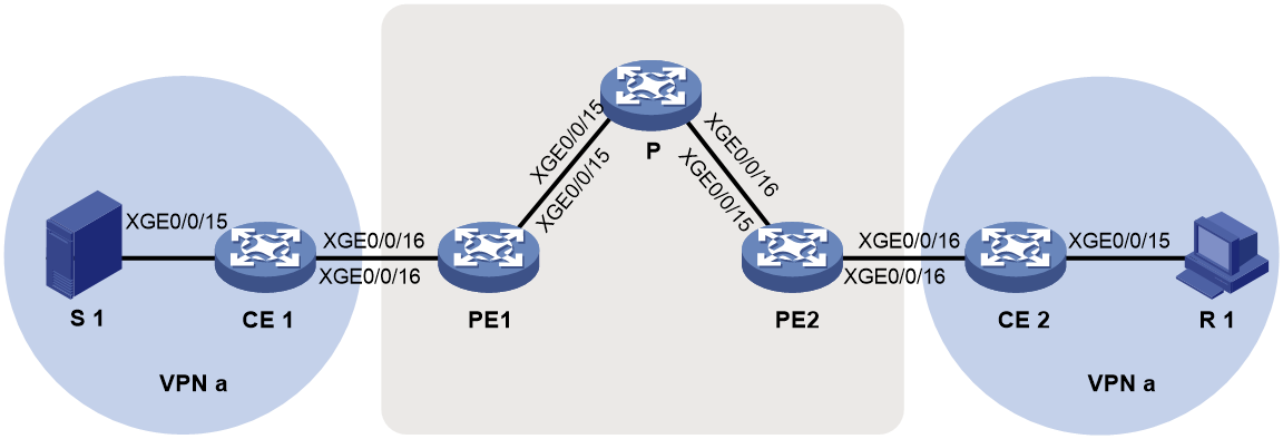
Table 1 Interface and IP address assignment
|
Device |
Interface |
IP address |
Device |
Interface |
IP address |
|
S 1 |
— |
10.110.7.2/24 |
R 1 |
— |
10.110.9.2/24 |
|
P |
XGE0/0/15 |
192.168.6.2/24 |
CE 1 |
XGE0/0/15 |
10.110.7.1/24 |
|
P |
XGE0/0/16 |
192.168.7.2/24 |
CE 1 |
XGE0/0/16 |
10.110.2.2/24 |
|
P |
Loop1 |
2.2.2.2/32 |
CE 2 |
XGE0/0/15 |
10.110.9.1/24 |
|
PE 1 |
XGE0/0/15 |
192.168.6.1/24 |
CE 2 |
XGE0/0/16 |
10.110.4.2/24 |
|
PE 1 |
XGE0/0/16 |
10.110.2.1/24 |
PE 2 |
XGE0/0/15 |
192.168.7.1/24 |
|
PE 1 |
Loop1 |
1.1.1.1/32 |
PE 2 |
XGE0/0/16 |
10.110.4.1/24 |
|
PE 1 |
Loop2 |
33.33.33.33/32 |
PE 2 |
Loop1 |
1.1.1.2/32 |
Procedure
1. Configure PE 1:
# Configure a global router ID.
<PE1> system-view
[PE1] router id 1.1.1.1
# Configure an LSR ID, and enable MPLS TE, MPLS LDP, and RSVP globally.
[PE1] mpls lsr-id 1.1.1.1
[PE1] mpls te
[PE1-te] quit
[PE1] rsvp
[PE1-rsvp] quit
[PE1] mpls ldp
[PE1-ldp] quit
# Create a VPN instance named a, and configure an RD and route targets for the VPN instance.
[PE1] ip vpn-instance a
[PE1-vpn-instance-a] route-distinguisher 100:1
[PE1-vpn-instance-a] vpn-target 100:1 export-extcommunity
[PE1-vpn-instance-a] vpn-target 100:1 import-extcommunity
[PE1-vpn-instance-a] quit
# Enable IP multicast routing in VPN instance a.
[PE1] multicast routing vpn-instance a
[PE1-mrib-a] quit
# Assign an IP address to Loopback 1.
[PE1] interface loopback 1
[PE1-LoopBack1] ip address 1.1.1.1 32
[PE1-LoopBack1] quit
# Create an RSVP-TE-based MVPN for VPN instance a.
[PE1] multicast-vpn vpn-instance a mode rsvp-te
# Create an MVPN IPv4 address family for VPN instance a.
[PE1-mvpn-vpn-instance-a] address-family ipv4
# Specify the MVPN source interface for VPN instance a.
[PE1-mvpn-vpn-instance-a-ipv4] source loopback 1
# Enable dynamic inclusive tunnel creation.
[PE1-mvpn-vpn-instance-a-ipv4] inclusive-tunnel dynamic
# Enable dynamic selective tunnel creation.
[PE1-mvpn-vpn-instance-a-ipv4] selective-tunnel dynamic
[PE1-mvpn-vpn-instance-a-ipv4] quit
[PE1-mvpn-vpn-instance-a] quit
# Assign an IP address to Ten-GigabitEthernet 0/0/15.
[PE1] interface ten-gigabitethernet 0/0/15
[PE1-Ten-GigabitEthernet0/0/15] ip address 192.168.6.1 24
# Enable MPLS, MPLS TE, MPLS LDP, and RSVP on Ten-GigabitEthernet 0/0/15.
[PE1-Ten-GigabitEthernet0/0/15] mpls enable
[PE1-Ten-GigabitEthernet0/0/15] mpls te enable
[PE1-Ten-GigabitEthernet0/0/15] mpls ldp enable
[PE1-Ten-GigabitEthernet0/0/15] rsvp enable
[PE1-Ten-GigabitEthernet0/0/15] quit
# Associate Ten-GigabitEthernet 0/0/16 with VPN instance a.
[PE1] interface ten-gigabitethernet 0/0/16
[PE1-Ten-GigabitEthernet0/0/16] ip binding vpn-instance a
# Assign an IP address to Ten-GigabitEthernet 0/0/16, and enable PIM-SM on the interface.
[PE1-Ten-GigabitEthernet0/0/16] ip address 10.110.2.1 24
[PE1-Ten-GigabitEthernet0/0/16] pim sm
[PE1-Ten-GigabitEthernet0/0/16] quit
# Associate Loopback 2 with VPN instance a.
[PE1] interface loopback 2
[PE1-LoopBack2] ip binding vpn-instance a
# Assign an IP address to Loopback 2, and enable PIM-SM on the interface.
[PE1-LoopBack2] ip address 33.33.33.33 32
[PE1-LoopBack2] pim sm
[PE1-LoopBack2] quit
# Configure Loopback 2 as a C-BSR and a C-RP.
[PE1] pim vpn-instance a
[PE1-pim-a] c-bsr 33.33.33.33
[PE1-pim-a] c-rp 33.33.33.33
[PE1-pim-a] quit
# Configure BGP.
[PE1] bgp 100
[PE1-bgp-default] peer 1.1.1.2 as-number 100
[PE1-bgp-default] peer 1.1.1.2 connect-interface loopback 1
[PE1-bgp-default] address-family ipv4 mvpn
[PE1-bgp-default-mvpn] peer 1.1.1.2 enable
[PE1-bgp-default-mvpn] quit
[PE1-bgp-default] address-family vpnv4
[PE1-bgp-default-vpnv4] mvpn-advertise-rt-import
[PE1-bgp-default-vpnv4] peer 1.1.1.2 enable
[PE1-bgp-default-vpnv4] quit
[PE1–bgp-default] ip vpn-instance a
[PE1-bgp-default-a] address-family ipv4 unicast
[PE1-bgp-default-ipv4-a] import-route rip 2
[PE1-bgp-default-ipv4-a] import-route direct
[PE1-bgp-default-ipv4-a] quit
[PE1-bgp-default-a] quit
[PE1–bgp-default] quit
# Configure OSPF.
[PE1] ospf 1
[PE1-ospf-1] area 0.0.0.0
[PE1-ospf-1-area-0.0.0.0] network 1.1.1.1 0.0.0.0
[PE1-ospf-1-area-0.0.0.0] network 192.168.6.0 0.0.0.255
[PE1-ospf-1-area-0.0.0.0] quit
[PE1-ospf-1] quit
# Configure RIP.
[PE1] rip 2 vpn-instance a
[PE1-rip-2] network 33.33.33.33 0.0.0.0
[PE1-rip-2] network 10.110.2.0 0.0.0.255
[PE1-rip-2] import-route bgp
[PE1-rip-2] quit
2. Configure PE 2:
# Configure a global router ID.
<PE2> system-view
[PE2] router id 1.1.1.2
# Configure an LSR ID, and enable MPLS TE, MPLS LDP, and RSVP globally.
[PE2] mpls lsr-id 1.1.1.2
[PE2] mpls te
[PE2-te] quit
[PE2] mpls ldp
[PE2-ldp] quit
[PE2] rsvp
[PE2-rsvp] quit
# Assign an IP address to Loopback 1.
[PE2] interface loopback 1
[PE2-LoopBack1] ip address 1.1.1.2 32
[PE2-LoopBack1] quit
# Create a VPN instance named a, and configure an RD and route targets for the VPN instance.
[PE2] ip vpn-instance a
[PE2-vpn-instance-a] route-distinguisher 100:1
[PE2-vpn-instance-a] vpn-target 100:1 export-extcommunity
[PE2-vpn-instance-a] vpn-target 100:1 import-extcommunity
[PE2-vpn-instance-a] quit
# Enable IP multicast routing for VPN instance a.
[PE2] multicast routing vpn-instance a
[PE2-mrib-a] quit
# Create an RSVP-TE-based MVPN for VPN instance a.
[PE2] multicast-vpn vpn-instance a mode rsvp-te
# Create an MVPN IPv4 address family for VPN instance a.
[PE2-mvpn-vpn-instance-a] address-family ipv4
# Specify the MVPN source interface for VPN instance a.
[PE2-mvpn-vpn-instance-a-ipv4] source loopback 1
# Enable dynamic inclusive tunnel creation.
[PE2-mvpn-vpn-instance-a-ipv4] inclusive-tunnel dynamic
# Enable dynamic selective tunnel creation.
[PE2-mvpn-vpn-instance-a-ipv4] selective-tunnel dynamic
[PE2-mvpn-vpn-instance-a-ipv4] quit
[PE2-mvpn-vpn-instance-a] quit
# Assign an IP address to Ten-GigabitEthernet 0/0/15.
[PE2] interface ten-gigabitethernet 0/0/15
[PE2-Ten-GigabitEthernet0/0/15] ip address 192.168.7.1 24
# Enable MPLS, MPLS TE, MPLS LDP, and RSVP on Ten-GigabitEthernet 0/0/15.
[PE2-Ten-GigabitEthernet0/0/15] mpls enable
[PE2-Ten-GigabitEthernet0/0/15] mpls te enable
[PE2-Ten-GigabitEthernet0/0/15] mpls ldp enable
[PE2-Ten-GigabitEthernet0/0/15] rsvp enable
[PE2-Ten-GigabitEthernet0/0/15] quit
# Associate Ten-GigabitEthernet 0/0/16 with VPN instance a.
[PE2] interface ten-gigabitethernet 0/0/16
[PE2-Ten-GigabitEthernet0/0/16] ip binding vpn-instance a
# Assign an IP address to Ten-GigabitEthernet 0/0/16, and enable PIM-SM on the interface.
[PE2-Ten-GigabitEthernet0/0/16] ip address 10.110.4.1 24
[PE2-Ten-GigabitEthernet0/0/16] pim sm
[PE2-Ten-GigabitEthernet0/0/16] quit
# Configure BGP.
[PE2] bgp 100
[PE2-bgp-default] peer 1.1.1.1 as-number 100
[PE2-bgp-default] peer 1.1.1.1 connect-interface loopback 1
[PE2-bgp-default] address-family ipv4 mvpn
[PE2-bgp-default-mvpn] peer 1.1.1.1 enable
[PE2-bgp-default-mvpn] quit
[PE2-bgp-default] address-family vpnv4
[PE2-bgp-default-vpnv4] mvpn-advertise-rt-import
[PE2-bgp-default-vpnv4] peer 1.1.1.1 enable
[PE2-bgp-default-vpnv4] quit
[PE2–bgp-default] ip vpn-instance a
[PE2-bgp-default-a] address-family ipv4 unicast
[PE2-bgp-default-ipv4-a] import-route rip 2
[PE2-bgp-default-ipv4-a] import-route direct
[PE2-bgp-default-ipv4-a] quit
[PE2-bgp-default-a] quit
[PE2–bgp-default] quit
# Configure OSPF.
[PE2] ospf 1
[PE2-ospf-1] area 0.0.0.0
[PE2-ospf-1-area-0.0.0.0] network 1.1.1.2 0.0.0.0
[PE2-ospf-1-area-0.0.0.0] network 192.168.7.0 0.0.0.255
[PE2-ospf-1-area-0.0.0.0] quit
[PE2-ospf-1] quit
# Configure RIP.
[PE2] rip 2 vpn-instance a
[PE2-rip-2] network 10.110.4.0 0.0.0.255
[PE2-rip-2] import-route bgp
[PE2-rip-2] quit
3. Configure P:
# Configure an LSR ID, and enable MPLS TE, MPLS LDP, and RSVP globally.
<P> system-view
[P] mpls lsr-id 2.2.2.2
[P] mpls te
[P-te] quit
[P] mpls ldp
[P-ldp] quit
[P] rsvp
[P-rsvp] quit
# Assign an IP address to Ten-GigabitEthernet 0/0/15.
[P] interface ten-gigabitethernet 0/0/15
[P-Ten-GigabitEthernet0/0/15] ip address 192.168.6.2 24
# Enable MPLS, MPLS TE, MPLS LDP, and RSVP on Ten-GigabitEthernet 0/0/15.
[P-Ten-GigabitEthernet0/0/15] mpls enable
[P-Ten-GigabitEthernet0/0/15] mpls te enable
[P-Ten-GigabitEthernet0/0/15] mpls ldp enable
[P-Ten-GigabitEthernet0/0/15] rsvp enable
[P-Ten-GigabitEthernet0/0/15] quit
# Assign an IP address to Ten-GigabitEthernet 0/0/16.
[P] interface ten-gigabitethernet 0/0/16
[P-Ten-GigabitEthernet0/0/16] ip address 192.168.7.2 24
# Enable MPLS, MPLS TE, MPLS LDP, and RSVP on Ten-GigabitEthernet 0/0/16.
[P-Ten-GigabitEthernet0/0/16] mpls enable
[P-Ten-GigabitEthernet0/0/16] mpls te enable
[P-Ten-GigabitEthernet0/0/16] mpls ldp enable
[P-Ten-GigabitEthernet0/0/16] rsvp enable
[P-Ten-GigabitEthernet0/0/16] quit
# Assign an IP address to Loopback 1.
[P] interface loopback 1
[P-LoopBack1] ip address 2.2.2.2 32
[P-LoopBack1] quit
# Configure OSPF.
[P] ospf 1
[P-ospf-1] area 0.0.0.0
[P-ospf-1-area-0.0.0.0] network 2.2.2.2 0.0.0.0
[P-ospf-1-area-0.0.0.0] network 192.168.6.0 0.0.0.255
[P-ospf-1-area-0.0.0.0] network 192.168.7.0 0.0.0.255
[P-ospf-1-area-0.0.0.0] quit
[P-ospf-1] quit
4. Configure CE 1:
# Enable IP multicast routing.
<CE1> system-view
[CE1] multicast routing
[CE1-mrib] quit
# Assign an IP address to Ten-GigabitEthernet 0/0/15, and enable PIM-SM on the interface.
[CE1] interface ten-gigabitethernet 0/0/15
[CE1-Ten-GigabitEthernet0/0/15] ip address 10.110.7.1 24
[CE1-Ten-GigabitEthernet0/0/15] pim sm
[CE1-Ten-GigabitEthernet0/0/15] quit
# Assign an IP address to Ten-GigabitEthernet 0/0/16, and enable PIM-SM on the interface.
[CE1] interface ten-gigabitethernet 0/0/16
[CE1-Ten-GigabitEthernet0/0/16] ip address 10.110.2.2 24
[CE1-Ten-GigabitEthernet0/0/16] pim sm
[CE1-Ten-GigabitEthernet0/0/16] quit
# Configure RIP.
[CE1] rip 2
[CE1-rip-2] network 10.110.2.0 0.0.0.255
[CE1-rip-2] network 10.110.7.0 0.0.0.255
[CE1-rip-2] quit
5. Configure CE 2:
# Enable IP multicast routing.
<CE2> system-view
[CE2] multicast routing
[CE2-mrib] quit
# Assign an IP address to Ten-GigabitEthernet 0/0/15, and enable IGMP on the interface.
[CE2] interface ten-gigabitethernet 0/0/15
[CE2-Ten-GigabitEthernet0/0/15] ip address 10.110.9.1 24
[CE2-Ten-GigabitEthernet0/0/15] igmp enable
[CE2-Ten-GigabitEthernet0/0/15] quit
# Assign an IP address to Ten-GigabitEthernet 0/0/16, and enable PIM-SM on the interface.
[CE2] interface ten-gigabitethernet 0/0/16
[CE2-Ten-GigabitEthernet0/0/16] ip address 10.110.4.2 24
[CE2-Ten-GigabitEthernet0/0/16] pim sm
[CE2-Ten-GigabitEthernet0/0/16] quit
# Configure RIP.
[CE2] rip 2
[CE2-rip-2] network 10.110.4.0 0.0.0.255
[CE2-rip-2] quit
Verifying the configuration
# Display the C-multicast A-D routing information VPN instance a on PE 1.
[PE1] display multicast-vpn vpn-instance a c-multicast routing-table
Total 0 (*, G) entry; 1 (S, G) entry
(10.110.7.2, 225.0.0.1)
CreateTime: 02:54:43
Tunnel Information: Tunnel1
Leaf neighbors information:
Total number of Leaf neighbors: 1
1: 1.1.1.2
# Display RSVP-TE tunnel neighbor information for VPN instance a on PE 1.
[PE1] display multicast-vpn vpn-instance a neighbor
MVPN Tunnel information sent by VPN instance: a
Total 1 Selective Tunnel in using
Total 0 Selective Tunnel in creating
Inclusive Tunnel: Tunnel0
Tunnel Identifier: RSVP P2MP <0x1010101, 0x0, 0x0, 0x1010101>
Neighbor State Up/DownTime
1.1.1.2 Up 02:53:58
Selective Tunnel: Tunnel1
Tunnel Identifier: RSVP P2MP <0x1010101, 0x0, 0x1, 0x1010101>
Neighbor State Up/DownTime
