- Table of Contents
-
- 01-Fundamentals Configuration Guide
- 00-Preface
- 01-CLI configuration
- 02-RBAC configuration
- 03-Login management configuration
- 04-FTP and TFTP configuration
- 05-File system management configuration
- 06-Configuration file management configuration
- 07-Multichassis configuration sync configuration
- 08-Software upgrade configuration
- 09-ISSU configuration
- 10-GIR configuration
- 11-Automatic configuration
- 12-Device management configuration
- 13-Target configuration management configuration
- 14-Tcl configuration
- 15-Python configuration
- Related Documents
-
| Title | Size | Download |
|---|---|---|
| 11-Automatic configuration | 465.07 KB |
Contents
Using server-based automatic configuration
About server-based automatic configuration
Typical server-based automatic configuration network
Selecting the interface used for automatic configuration
Server-based automatic configuration tasks at a glance
Starting and completing automatic configuration
Stopping automatic configuration
Using USB-based automatic configuration
About USB-based automatic configuration
Configuring and using index file-based automatic configuration
Configuring and using automatic configuration without an index file
Server-based automatic configuration examples
Example: Using a TFTP server for automatic configuration
Example: Using an HTTP server and Tcl scripts for automatic configuration
Example: Using an HTTP server and Python scripts for automatic configuration
Example: Using an SFTP server for automatic configuration
Example: Using an FTP server for automatic configuration
Example: Setting up an IRF fabric
Using automatic configuration
About automatic configuration
When the device starts up without a valid next-startup configuration file, the device searches the root directory of its default file system for the autocfg.py, autocfg.tcl, and autocfg.cfg files. Only one of files might exist in the root directory. If any one of the files exists, the device loads the file. If none of the files exists, the device uses the automatic configuration feature to obtain a set of configuration settings.
With the automatic configuration feature, the device can automatically obtain a set of configuration settings at startup. This feature simplifies network configuration and maintenance.
Automatic configuration can be implemented by using the implementation methods in Table 1.
Table 1 Automatic configuration implementation methods
|
Implementation method |
Configuration file location |
Application scenarios |
|
Server-based automatic configuration |
File server |
A number of geographically distributed devices need to be configured. |
|
USB-based automatic configuration |
USB disk |
· On a small network, the devices reside near to each other, and no host can be used as a file server. · On a large network, only a few devices require automatic configuration or configuration update. |
If both server-based automatic configuration and USB-based automatic configuration are available, the device prefers USB-based automatic configuration.
Using server-based automatic configuration
About server-based automatic configuration
With server-based automatic configuration, a device without a configuration file can run the DHCP client to obtain a configuration file from a file server at startup.
You can deploy server-based automatic configuration on both IPv4 and IPv6 networks by using the same method. This chapter describes the tasks for deploying server-based automatic configuration on an IPv4 network.
Typical server-based automatic configuration network
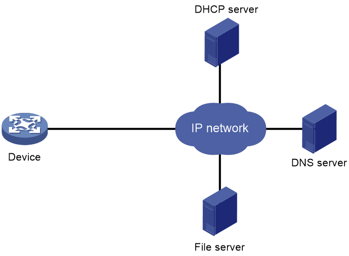
As shown in Figure 1, a typical server-based automatic configuration network consists of the following servers:
· DHCP server—Allocates an IP address to the device that performs server-based automatic configuration and notifies the device of the method to obtain the configuration file or script file for automatic configuration.
· File server—TFTP, HTTP, SFTP, or FTP server. The file server stores the configuration file or script file for automatic configuration.
· (Optional.) DNS server—Obtains the configuration file name or the IP address of the file server for the device.
Figure 1 Server-based automatic configuration network diagram
Host name file
A host name file stores mappings between host IP addresses and host names. To configure a host name file:
1. Create a host name file. The file name must be network.cfg.
2. Add each mapping entry in the ip host host-name ip-address format on a separate line. For example:
ip host host1 101.101.101.101
ip host host2 101.101.101.102
ip host client1 101.101.101.103
ip host client2 101.101.101.104
|
|
IMPORTANT: The host name for a device must be the same as the name of the configuration file configured for the device. For example, the name of the configuration file for the device at 101.101.101.101 is host1.cfg. |
Selecting the interface used for automatic configuration
The device uses the following steps to select the interface for automatic configuration:
1. Identifies the status of the management Ethernet interface at Layer 2. If the management Ethernet interface is up, the device uses that interface.
2. Identifies the status of Layer 2 Ethernet interfaces. If one or more Layer 2 Ethernet interfaces are in up state, the device uses the VLAN interface of the default VLAN.
3. Sorts all Layer 3 Ethernet interfaces in up state first in lexicographical order of interface types and then in ascending order of interface numbers. Uses the interface with the smallest interface number among the interfaces of the first interface type.
4. If no Layer 3 Ethernet interfaces are in up state, the device waits 30 seconds and goes to step 1 to try again.
For fast automatic device configuration, connect only the management Ethernet interface on each device to the network.
Operating mechanism
The process for server-based automatic configuration for a device is as follows:
1. The device selects the interface used to obtain the configuration file or script file for automatic configuration and sends an IP request message to the DHCP server. For more information about the interface selection order, see "Selecting the interface used for automatic configuration."
2. After the DHCP server receives the IP request message, it sends a reply message to the device. If the device does not receive any reply message within the timeout period of the request message, it selects the next interface according to the interface selection order and sends the IP request message again.
3. The device parses the reply message.
¡ Obtains the IP address included in the reply message and uses it as the IP address for the selected interface to connect to the DHCP server. If the interface already has an IP address assigned, the device replaces the original IP address with the one included in the reply message. Once the automatic configuration process is complete, the device restores the original IP address to the interface.
¡ Obtains the protocol information (HTTP, TFTP, SFTP, or FTP), configuration file name information, and file server address included in the reply message.
4. If no configuration file name is obtained or the obtained configuration file name does not meet the requirements, the device uses file network.cfg on the file server. If file network.cfg does not exist, the device uses file device.cfg on the file server. If file device.cfg does not exist, the device fails to obtain the configuration file or script file. In this case, the process returns to step 1.
5. The device resolves the domain name of the file server. If the file server address included in the reply message is a domain name rather than an IP address, the device uses the DNS server to resolve the domain name to an IP address.
6. The device downloads the configuration file or script file used for automatic configuration from the file server based on the obtained protocol, file server address, and configuration file name.
7. The device deploys the configuration in the configuration file or executes the script file.
8. The device automatically deletes the configuration file or script file.
Server-based automatic configuration tasks at a glance
To configure server-based automatic configuration, perform the following tasks:
1. Prepare the files for automatic configuration:
¡ Preparing configuration files
2. Configuring the file server
3. Configuring the DHCP server
4. (Optional.) Configuring the DNS server
5. (Optional.) Configuring the gateway
6. Starting and completing automatic configuration
7. (Optional.) Stopping automatic configuration
Preparing configuration files
Configuration file types
The device supports the configuration file types listed in Table 2.
Table 2 Configuration file types
|
Configuration file type |
Application objects |
File name requirements |
Supported file server types |
|
Dedicated configuration file |
Devices that require different settings |
File name.cfg For simple file name identification, use configuration file names that do not contain spaces. |
· HTTP server · TFTP server · SFTP server · FTP server |
|
Common configuration file |
Devices that share all or some settings |
File name.cfg For simple file name identification, use configuration file names that do not contain spaces. |
· HTTP server · TFTP server · SFTP server · FTP server |
|
Default configuration file |
All devices. The file contains only common configurations that devices use to start up. |
device.cfg |
TFTP server |
Identifying requirements for and preparing configuration files
1. Identify the requirements of the devices for configuration files.
2. For devices that require different configurations, prepare a configuration file for each of them and save the files to the file server.
3. For devices that share all or some configurations, save the common configurations to a .cfg file on the file server.
4. If a TFTP file server is used, you can save the common configurations that devices use to start up to the device.cfg file on the server. The file is assigned to a device only when the device does not have any other configuration file to use.
Preparing a host name file on the file server
If the DHCP server does not assign configuration file names, you can configure a host name file on the file server. The host name file contains the host name-IP address mappings of the devices to be automatically configured. As the host name for a device is the same as the name of the configuration file configured for the device, the device can obtain the configuration file configured for it.
Preparing script files
About this task
Script files can be used for automatic software upgrade and automatic configuration.
The devices support Python scripts (.py files) and Tcl scripts (.tcl files). For more information about Python and Tcl scripts, see "Using Python" and "Using Tcl."
The devices support dedicated script files and common dedicated script files. They do not support using a default script file. For information about dedicated script files and common dedicated script files, see Table 2.
When script files are used, you cannot use a host name file to provide the host name-IP address mappings for devices.
Restrictions and guidelines
To use a Tcl script, make sure all commands in the script are supported and correctly configured. Any error in a command causes the automatic configuration process to quit.
When you use a Python script to automatically configure a device, make sure the script file does not contain command line errors (such as spelling mistakes, incorrect views, and unsupported commands for the device). If the script file contains command line errors, the current round of automatic configuration will fail and the device will proceed to the next round of automatic configuration.
When you use a Python script to automatically configure a device, the device is in the startup phase and the device is unstable. Therefore, do not use the Stable value in the display system stable state command output as the judgment condition in the Python script.
Procedure
· For devices that share all or some configurations, create a script file that contains the common configurations.
· For the other devices, create a separate script file for each of them.
Configuring the file server
For devices to obtain configuration information from an HTTP, TFTP, SFTP, or FTP server, start HTTP, TFTP, SFTP, or FTP service on the file server, respectively.
Configuring the DHCP server
About this task
The DHCP server assigns the following items to devices that need to be automatically configured:
· IP addresses.
· Paths of the configuration or script files.
Restrictions and guidelines
When you configure the DHCP server, follow these guidelines:
· For devices for which you have prepared different configuration files, perform the following tasks for each of the devices on the DHCP server:
¡ Create a DHCP address pool.
¡ Configure a static address binding.
¡ Specify a configuration file or script file.
Because an address pool can use only one configuration file, you can specify only one static address binding for an address pool.
· For devices for which you have prepared the same configuration file, use either of the following methods:
¡ Method 1:
- Create a DHCP address pool for the devices.
- Configure a static address binding for each of the devices in the address pool.
- Specify the configuration file for the devices.
¡ Method 2:
- Create a DHCP address pool for the devices.
- Specify the subnet for dynamic allocation.
- Specify the TFTP server.
- Specify the configuration file for the devices.
· If all devices on a subnet share the same configuration file or script file, perform the following tasks on the DHCP server:
¡ Configure dynamic address allocation.
¡ Specify the configuration file or script file for the devices.
The configuration file can contain only the common settings for the devices. You can provide a method for the device administrators to change the configurations after their devices start up.
When you specify a startup configuration file on a remote server for a DHCP client, follow these restrictions and guidelines:
· If a TFTP server is used, you must specify the file name. If the file name contains special characters, you must transcode the special characters according to the RFC specification.
· If an HTTP server is used, you must specify the URL of the file in the format of http://HTTP-server-IP-address:port-number/path/file-name. If the path or file name in the URL contains special characters, you must transcode the special characters according to the RFC specification. If you do not specify a port number, the default port number applies.
· If an FTP server is used, you must specify the URL of the file in the format of ftp://username:password@FTP-server-IP-address:port-number/path/file-name. If the username, password, path, or file name in the URL contains special characters, you must transcode the special characters according to the RFC specification. If you do not specify a port number, the default port number applies. If you do not specify a path, the root directory of the server applies.
· If an SFTP server is used, you must specify the URL of the file in the format of sftp://username:password@SFTP-server-IP-address:port-number/path/file-name. If the username, password, path, or file name in the URL contains special characters, you must transcode the special characters according to the RFC specification. If you do not specify a port number, the default port number applies. If you do not specify a path, the root directory of the server applies.
Configuring the DHCP server when an HTTP file server is used
1. Enter system view.
system-view
2. Enable DHCP.
dhcp enable
By default, DHCP is disabled.
3. Create a DHCP address pool and enter its view.
dhcp server ip-pool pool-name
4. Configure the address pool.
Choose the options to configure as needed:
¡ Specify the primary subnet for the address pool.
network network-address [ mask-length | mask mask ]
By default, no primary subnet is specified.
¡ Configure a static binding.
static-bind ip-address ip-address [ mask-length | mask mask ] { client-identifier client-identifier | hardware-address hardware-address [ ethernet | token-ring ] }
By default, no static binding is configured.
You can configure multiple static bindings. However, one IP address can be bound to only one client. To change the binding for a DHCP client, you must remove the binding and reconfigure a binding.
5. Specify the URL of the configuration or script file in HTTP format.
bootfile-name url
By default, no configuration or script file URL is specified in HTTP format.
Configuring the DHCP server when a TFTP file server is used
1. Enter system view.
system-view
2. Enable DHCP.
dhcp enable
By default, DHCP is disabled.
3. Create a DHCP address pool and enter its view.
dhcp server ip-pool pool-name
4. Configure the address pool.
Choose the options to configure as needed:
¡ Specify the primary subnet for the address pool.
network network-address [ mask-length | mask mask ]
By default, no primary subnet is specified.
¡ Configure a static binding.
static-bind ip-address ip-address [ mask-length | mask mask ] { client-identifier client-identifier | hardware-address hardware-address [ ethernet | token-ring ] }
By default, no static binding is configured.
You can configure multiple static bindings. However, one IP address can be bound to only one client. To change the binding for a DHCP client, you must remove the binding and reconfigure a binding.
5. Specify a TFTP server.
Choose one option as needed:
¡ Specify the IP address of the TFTP server.
tftp-server ip-address ip-address
By default, no TFTP server IP address is specified.
¡ Specify the name of the TFTP server.
tftp-server domain-name domain-name
By default, no TFTP server name is specified.
If you specify a TFTP server by its name, a DNS server is required on the network.
6. Specify the name of the configuration or script file.
bootfile-name bootfile-name
By default, no configuration or script file name is specified.
Configuring the DHCP server when an SFTP file server is used
1. Enter system view.
system-view
2. Enable DHCP.
dhcp enable
By default, DHCP is disabled.
3. Create a DHCP address pool and enter its view.
dhcp server ip-pool pool-name
4. Configure the address pool.
Choose the options to configure as needed:
¡ Specify the primary subnet for the address pool.
network network-address [ mask-length | mask mask ]
By default, no primary subnet is specified.
¡ Configure a static binding.
static-bind ip-address ip-address [ mask-length | mask mask ] { client-identifier client-identifier | hardware-address hardware-address [ ethernet | token-ring ] }
By default, no static binding is configured.
You can configure multiple static bindings. However, one IP address can be bound to only one client. To change the binding for a DHCP client, you must remove the binding and reconfigure a binding.
5. Specify the URL of the configuration or script file in SFTP format.
bootfile-name url
By default, no configuration or script file URL in SFTP format is specified.
Configuring the DHCP server when an FTP file server is used
1. Enter system view.
system-view
2. Enable DHCP.
dhcp enable
By default, DHCP is disabled.
3. Create a DHCP address pool and enter its view.
dhcp server ip-pool pool-name
4. Configure the address pool.
Choose the options to configure as needed:
¡ Specify the primary subnet for the address pool.
network network-address [ mask-length | mask mask ]
By default, no primary subnet is specified.
¡ Configure a static binding.
static-bind ip-address ip-address [ mask-length | mask mask ] { client-identifier client-identifier | hardware-address hardware-address [ ethernet | token-ring ] }
By default, no static binding is configured.
You can configure multiple static bindings. However, one IP address can be bound to only one client. To change the binding for a DHCP client, you must remove the binding and reconfigure a binding.
5. Specify the URL of the configuration or script file in FTP format.
bootfile-name url
By default, no configuration or script file URL in FTP format is specified.
Configuring the DNS server
A DNS server is required in the following situations:
· Obtaining the names of configuration files for automatic configuration when the TFTP server does not have a host name file—In this situation, the devices that perform server-based automatic configuration use the DNS server to resolve their IP addresses to their host names. Then, each device can use its host name to obtain the configuration file that has the same name as its host name from the TFTP server.
· Obtaining the IP address of a file server—If the devices obtain the domain name of the file server from DHCP reply messages, they can use the domain name to obtain the IP address of the file server through the DNS server.
For more information about DNS servers, see DNS configuration in Layer 3—IP Services Configuration Guide.
Configuring the gateway
If the devices to be automatically configured and the servers for automatic configuration reside in different network segments, you must perform the following tasks:
· Deploy a gateway and make sure the devices can communicate with the servers.
· Configure the DHCP relay agent feature on the gateway.
· Configure the UDP helper feature on the gateway.
This task is required if devices send requests to a TFTP server by using broadcast packets. A device uses broadcast packets to send requests to a TFTP server in the following situations:
¡ The DHCP reply does not contain the IP address or domain name of the TFTP server.
¡ The IP address or domain name of the TFTP server is invalid.
The UDP helper transforms a broadcast packet into a unicast packet and forwards the unicast packet to the file server. For more information about UDP helper, see Layer 3—IP Services Configuration Guide.
Starting and completing automatic configuration
1. Power on the devices to be automatically configured.
2. The devices enter the automatic configuration process. After a device obtains a configuration file and executes the file successfully, the automatic configuration process ends.
3. Save the running configuration.
save
As a best practice, save the running configuration on each device after the configuration file is executed successfully on the device.
For more information about the save command, see configuration file management commands in Fundamentals Command Reference.
Stopping automatic configuration
If a device cannot obtain a configuration file for automatic configuration, the current automatic configuration attempt fails, and the device continues attempting automatic configuration. You can wait until the device automatically ends the automatic configuration process after it has made the maximum number of attempts. Alternatively, you can manually stop the automatic configuration process by using shortcut keys Ctrl+C or Ctrl+D based on the prompt information. After the automatic configuration process fails and ends, the device starts up with initial settings.
Using USB-based automatic configuration
About USB-based automatic configuration
When a device enters the automatic configuration process after it starts up with initial settings, it first attempts to load configuration from a USB disk. USB-based automatic configuration supports the following methods:
· Index file-based automatic configuration.
· Automatic configuration without an index file.
A device prefers index file-based automatic configuration to automatic configuration without an index file.
Configuring and using index file-based automatic configuration
Operating mechanism
Save an index file and configuration file on a USB disk. When a device starts, it automatically obtains and executes the configuration file on the USB disk based on the index file for automatic configuration.
The process for index file-based automatic configuration for a device is as follows:
1. The device detects that a USB disk is present.
2. Check whether the index file named smart_config.ini exists on the USB disk.
¡ If the index file named smart_config.ini exists, the device enters step 3.
¡ If the index file named smart_config.ini does not exist, the device performs automatic configuration without an index file. For more information, see "Configuring and using automatic configuration without an index file."
3. Check whether the format of the smart_config.ini index file is valid.
¡ If the index file is valid, the device enters step 4.
¡ If the index file is invalid, USB-based automatic configuration fails and the automatic configuration process ends. An error report is generated on the USB disk.
¡ If they are different, the device enters step 5.
¡ If they are the same, USB-based automatic configuration fails and the automatic configuration process ends. An error report is generated on the USB disk.
¡ If the device obtains the configuration file successfully, it enters step 6.
¡ If the device fails to obtain the configuration file, USB-based automatic configuration fails and the automatic configuration process ends. An error report is generated on the USB disk.
¡ If a reboot is not required, the device activates the files specified in the index file online and proceeds to step 7.
¡ If a reboot is required, the device sets the files specified in the index file as the next-startup files. After a successful automatic reboot, the device proceeds to step 7.
8. Remove the USB disk from the device.
Prerequisites
Create an index file and save it to the root directory of the USB disk. Save the required files to the directory specified in the index file on the USB disk.
Creating an index file
The name of the index file must be smart_config.ini.
To use index file-based automatic configuration, you can edit the index file for USB-based automatic configuration on your PC as follows:
1. Create an empty .txt file.
2. Edit the file contents according to the format of the index file for USB-based automatic configuration.
3. Save the .txt file as smart_config.ini.
4. Copy the index file named smart_config.ini to the root directory of the USB disk.
The index file format is as follows:
BEGIN LSW
[GLOBAL CONFIG]
TIMESN=
AUTOOVERWRITEFILE=
AUTODELFILE=
ACTIVEMODE=
[DEVICE DESCRIPTION]
OPTION=
SN=
MAC=
AUTODELFILE=
ACTIVEMODE=
DEVICETYPE=
DIRECTORY=
SYSTEM-IPE=
SYSTEM-BOOT-BIN=
SYSTEM-SYSTEM-BIN=
SYSTEM-FEATURE-BIN=
SYSTEM-FEATURE-BIN=
SYSTEM-FEATURE-BIN=
SYSTEM-PATCH-BIN=
SYSTEM-CONFIG=
END LSW
Table 3 shows the description for parameters in the index file.
Table 3 Description for parameters in the index file
|
Parameter |
Description |
|
BEGIN LSW |
Required. Start flag. It cannot be modified. |
|
[GLOBAL CONFIG] |
Required. Global configuration start flag. It cannot be modified. |
|
TIMESN |
Required. Data change time flag, in string format. It can contain 1 to 16 characters, and cannot contain spaces. Recommended format: year month day.hour minute second. For example, you can set TIMESN=20110628.080910 to represent 08:09:10 28 June 2011. Each TIMESN value corresponds to a device that will be upgraded. During the USB-based automatic configuration process, a device records its own TIMESN value before it reboots. If a reboot is not required for the upgrade, the device records its own TIMESN value when the upgrade is complete. This TIMESN value cannot be used in the next upgrade. When some devices fail to be upgraded, you must change their TIMESN values before performing another USB-based automatic configuration. |
|
AUTODELFILE |
Optional. Specifies whether to automatically delete the old software package after upgrade. Options include: · YES—Delete. · NO—Not delete By default, the value for the AUTODELFILE parameter is NO. If this parameter does not exist or the value for this parameter is empty or invalid, the default setting applies. AUTODELFILE parameters include two types, global and device-specific. · The parameters in the [GLOBAL CONFIG] area are global, and the parameters in the [DEVICE DESCRIPTION] area are device-specific. · If this parameter is set to YES or NO for a specific device, the device-specific configuration takes effect. If this parameter is not set or is empty for a specific device, the global configuration for this parameter takes effect on the device. |
|
AUTOOVERWRITEFILE |
Optional. Specifies whether to overwrite a configuration file on a device when a configuration file with the same name is copied from a USB disk to the device. · YES—Overwrite. · NO—Not overwrite. By default, the value for the AUTOOVERWRITEFILE parameter is YES. If this parameter does not exist or the value for this parameter is empty or invalid, the default setting applies. |
|
ACTIVEMODE |
Optional. Specifies the file activation method after a file is copied. Options include: · DEFAULT—Activates a file by its own default activation method. The default activation method is rebooting devices for system software. The default activation method is online activation without rebooting devices for configuration files and patch files. · REBOOT—Activates a file by rebooting the device. By default, the value for the ACTIVEMODE parameter is DEFAULT. If this parameter does not exist or the value for this parameter is empty or invalid, the default setting applies. ACTIVEMODE parameters include two types, global and device-specific. · The parameters in the [GLOBAL CONFIG] area are global, and the parameters in the [DEVICE DESCRIPTION] area are device-specific. · If this parameter is set to DEFAULT or REBOOT for a specific device, the device-specific configuration takes effect. If this parameter is not set or is empty for a specific device, the global configuration for this parameter takes effect on the device. |
|
[DEVICE DESCRIPTION] |
Required. Start flag for a device-specific configuration file. Each parameter in a device-specific configuration file cannot be repeated. If a device-specific configuration file contains repeated parameters, no device can match it. Each device can match only one device-specific configuration file. After a device matches a device-specific configuration file, it stops matching the subsequent device-specific configuration files. |
|
OPTION |
Optional. Validity flag for a device-specific configuration file, which indicates whether the device configuration file is valid. Options include: · OK—Valid. · NOK—Invalid. All information in the device-specific configuration file will not be used for device matching. By default, the value for the OPTION parameter is OK. If this parameter does not exist or the value for this parameter is empty or invalid, the default setting applies. |
|
SN |
Optional. Device serial number. If the value for the SN parameter is DEFAULT, the device SN will not be matched. Otherwise, the device SN will be matched. By default, the value for the SN parameter is DEFAULT. If this parameter does not exist or the value for this parameter is empty, the default setting applies. |
|
MAC |
Optional. Device MAC address, in the format of XXXX-XXXX-XXXX, where X is a hexadecimal digit. If the value for this parameter is DEFAULT, the device MAC address will not be matched. Otherwise, the device MAC address will be matched. By default, the value for the MAC parameter is DEFAULT. If this parameter does not exist or the value for this parameter is empty, the default setting applies. |
|
DEVICETYPE |
Optional. Matches the device type, for example, S12700. If the value for the DEVICETYPE parameter is DEFAULT, the device type will not be matched. Otherwise, the device type will be matched. By default, the value for the DEVICETYPE parameter is DEFAULT. If this parameter does not exist or the value for this parameter is empty, the default setting applies. |
|
DIRECTORY |
Optional. Directory for saving the software package and configuration file on the USB disk. · When the value for this parameter is empty or this parameter does not exist, the software package and configuration file will be saved in the root directory of the USB disk. · When DIRECTORY is set to /abc, the software package and configuration file will be saved in the abc directory in the USB disk. By default, the value for the DIRECTORY parameter is empty. The file directory format in the index file must be the same as that of the file system in the device. · The specified directory can contain a maximum of four levels. A directory must start with a slash (/), and different levels are separated by using slashes (/). However, a directory cannot end with a slash (/). For example, /abc/test is a valid directory, and /abc/test/ is an invalid directory. · The string in each level of a directory is 1 to 15 characters. · A directory cannot contain spaces or the following characters: ~ * / \ : ' " < > | ? [ ] %. A directory is case insensitive. |
|
SYSTEM-IPE |
Optional. IPE file name, which ends with .ipe. |
|
SYSTEM-BOOT-BIN |
Optional. Boot file name, which ends with .bin. |
|
SYSTEM-SYSTEM-BIN |
Optional. System file name, which ends with .bin. |
|
SYSTEM-FEATURE-BIN |
Optional. Feature file name, which ends with .bin. |
|
SYSTEM-PATCH-BIN |
Optional. Patch file name, which ends with .bin. |
|
SYSTEM-CONFIG |
Optional. Configuration file name, which ends with .cfg. |
|
END LSW |
Required. End flag of the file. |
|
|
CAUTION: When editing an index file for USB-based automatic configuration, make sure the contents in the index file are correct. The devices to be upgraded are matched in the order of the DEVICE parameters in the index file from top to bottom. A device is matched in the following order: MAC > SN > DEVICETYPE. Once a match is found, the files in the matching DEVICE information are loaded. If an error occurs during this process, the whole USB-based automatic configuration process is terminated, and an error report is output. The configuration will not be rolled back for devices that have been upgraded successfully. |
When you use an index file for automatic configuration, the device will confirm the files to be loaded according to the index file as follows:
1. The device identifies whether an .ipe file is specified in the index file. If yes, the device confirms loading the .ipe file, skips step 2, and proceeds with 3. If not, the device skips step 1 and proceeds with step 2.
2. The device identifies whether the index file has boot, system, and feature files specified. If yes, the specified files are loaded. The boot and system files are required, and the feature file is optional. After the files to be loaded are confirmed, the device proceeds with step 3. If no boot, system, or feature file is specified in the index file, the device skips step 2 and proceeds with step 3.
3. The device identifies whether a patch file is specified in the index file. If yes, the device confirms loading the patch file, skips steps 3, and proceeds with step 4. If not, the device skips step 3 and proceeds with step 4.
After step 4, the device starts loading the files to be loaded. If files fail to be loaded, the USB-based automatic configuration process will be stopped.
|
|
NOTE: · When editing an index file, you must press Enter after entering a line in the specified format and then editing new contents. After editing the index file, save the index file. · If the keyword of a parameter is not matched or found, the parameter is considered as empty. · When the value for a parameter in the GLOBAL CONFIG area is different from that in the DEVICE DESCRIPTION area for a matching device, the configuration in the DEVICE DESCRIPTION area takes effect on the device. |
Procedure
1. Enable USB-based automatic configuration on the device:
a. Enter system view.
system-view
b. Enable USB-based automatic configuration.
autodeploy udisk enable
By default, USB-based automatic configuration is enabled.
For the enabling configuration to take effect if USB-based automatic configuration has been disabled, you must save the configuration and reboot the device.
c. Save the running configuration.
save
2. Create an index file.
3. Save the index file to the root directory of the USB disk, and save the files specified in the index file to the specified directory. By default, the directory is the root directory of the USB disk.
4. Insert the USB disk into interface USB1, namely, usba0:, on the active MPU. USB-based automatic configuration is supported only by a single MPU. After USB-based automatic configuration ends, the standby MPU will automatically synchronize its configuration with the active MPU at startup.
5. Observe the LEDs of the device.
¡ If the SYS LED flashes green quickly for 5 seconds, the automatic configuration succeeds. Proceed to step 6.
¡ If the SYS LED flashes yellow quickly for 10 seconds, the automatic configuration fails. Display the log file named fully qualified configuration file name.log in the root directory of the USB disk to locate and resolve the issue.
How LED status reflects automatic configuration results depends on the device model.
6. Use the display current-configuration command to verify that the configuration file has been loaded correctly. For more information about this command, see configuration file management in Fundamentals Command Reference.
7. Remove the USB disk.
Configuring and using automatic configuration without an index file
Operating mechanism
Save a configuration file on a USB disk. When a device starts, it automatically obtains and executes the configuration file from the USB disk for automatic configuration.
The process for USB-based automatic configuration without an index file is as follows:
1. The device detects that the USB disk is present.
2. Check whether the index file named smart_config.ini exists on the USB disk.
¡ If the index file named smart_config.ini exists, the device performs index file-based automatic configuration. For more information, see "Configuring and using index file-based automatic configuration."
¡ If the index file named smart_config.ini does not exist, proceed to step 3.
3. Manually reboot the device.
4. When the device starts up, it detects whether a .cfg configuration file exists on the USB disk.
¡ If a .cfg file exists, the device proceeds to step 5.
¡ If no .cfg file exists, the USB-based automatic configuration process ends.
5. After the device obtains a configuration file from the USB disk, it compares the content of the configuration file with the content of the current main next-startup configuration file on the device.
¡ If the contents are the same, the device directly loads the main next-startup configuration file instead of the configuration file on the USB disk.
¡ If the contents are different, the device copies the configuration file on the USB disk to the local storage medium and proceeds to step 6.
If the device has a local file that uses the same name as the configuration file copied from the USB disk, it handles the local file as follows:
- If the local file is the main next-startup configuration file, the device saves the file as original-file-name_bak.cfg.
- If the local file is not the main next-startup configuration file, the device directly uses the configuration file copied from the USB disk to overwrite the local file.
6. The device executes the configuration file copied from the USB disk.
¡ If the execution succeeds, the device automatically runs the configuration in the configuration file as the running configuration and sets the configuration file as the main next-startup configuration file.
¡ If the device fails to execute any command in the configuration file, it ignores all settings in the configuration file and loads settings in the original next-startup configuration file. If no next-startup configuration file is available, the device starts up with initial settings.
Prerequisites
1. Prepare a USB disk that has only one partition.
2. Display the serial number of the device.
display device manuinfo
For more information about this command, see device management commands in Fundamentals Command Reference.
3. Create a configuration file named device serial number.cfg or autodeploy.cfg, and save the file to the root directory of the file system on the USB disk.
If a configuration file named device serial number.cfg coexists with configuration file autodeploy.cfg, the configuration file named device serial number.cfg is used.
Procedure
1. Enable USB-based automatic configuration on the device:
a. Enter system view.
system-view
b. Enable USB-based automatic configuration.
autodeploy udisk enable
By default, USB-based automatic configuration is enabled.
For the enabling configuration to take effect if USB-based automatic configuration has been disabled, you must save the configuration and reboot the device.
c. Save the running configuration.
save
2. Insert the USB disk with the configuration file saved into interface USB1, namely, usba0:, on the active MPU. USB-based automatic configuration is supported only by a single MPU. After USB-based automatic configuration ends, the standby MPU will automatically synchronize its configuration with the active MPU at startup.
3. Reboot the device and observe the LEDs of the device.
¡ If the SYS LED flashes green quickly for 5 seconds, the automatic configuration succeeds. Proceed to step 4.
¡ If the SYS LED flashes yellow quickly for 10 seconds, the automatic configuration fails. Display the log file named fully qualified configuration file name.log in the root directory of the USB disk to locate and resolve the issue.
How LED status reflects automatic configuration results depends on the device model.
4. Use the display current-configuration command to verify that the configuration file has been loaded correctly.
For more information about this command, see configuration file management commands in Fundamentals Command Reference.
5. Remove the USB disk.
Server-based automatic configuration examples
Example: Using a TFTP server for automatic configuration
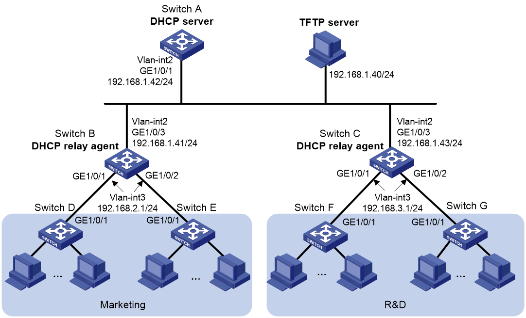
Network configuration
As shown in Figure 2, two departments of a company are connected to the network through gateways (Switch B and Switch C). Access devices Switch D, Switch E, Switch F, and Switch G do not have a configuration file.
Configure the servers and gateways so the access devices can obtain a configuration file to complete the following configuration tasks:
· Enable administrators of access devices to Telnet to and manage their respective access devices.
· Require administrators to enter their respective usernames and passwords at login.
Procedure
1. Configure the DHCP server:
# Create a VLAN interface and assign an IP address to the interface.
<SwitchA> system-view
[SwitchA] vlan 2
[SwitchA-vlan2] port gigabitethernet 1/0/1
[SwitchA-vlan2] quit
[SwitchA] interface vlan-interface 2
[SwitchA-Vlan-interface2] ip address 192.168.1.42 24
[SwitchA-Vlan-interface2] quit
# Enable DHCP.
[SwitchA] dhcp enable
# Enable the DHCP server on VLAN-interface 2.
[SwitchA] interface vlan-interface 2
[SwitchA-Vlan-interface2] dhcp select server
[SwitchA-Vlan-interface2] quit
# Configure address pool market to assign IP addresses on the 192.168.2.0/24 subnet to clients in the Marketing department. Specify the TFTP server, gateway, and configuration file name for the clients.
[SwitchA] dhcp server ip-pool market
[SwitchA-dhcp-pool-market] network 192.168.2.0 24
[SwitchA-dhcp-pool-market] tftp-server ip-address 192.168.1.40
[SwitchA-dhcp-pool-market] gateway-list 192.168.2.1
[SwitchA-dhcp-pool-market] bootfile-name market.cfg
[SwitchA-dhcp-pool-market] quit
# Configure address pool rd to assign IP addresses on the 192.168.3.0/24 subnet to clients in the R&D department. Specify the TFTP server, gateway, and configuration file name for the clients.
[SwitchA] dhcp server ip-pool rd
[SwitchA-dhcp-pool-rd] network 192.168.3.0 24
[SwitchA-dhcp-pool-rd] tftp-server ip-address 192.168.1.40
[SwitchA-dhcp-pool-rd] gateway-list 192.168.3.1
[SwitchA-dhcp-pool-rd] bootfile-name rd.cfg
[SwitchA-dhcp-pool-rd] quit
# Configure static routes to the DHCP relay agents.
[SwitchA] ip route-static 192.168.2.0 24 192.168.1.41
[SwitchA] ip route-static 192.168.3.0 24 192.168.1.43
[SwitchA] quit
2. Configure the gateway Switch B:
# Create VLAN interfaces and assign IP addresses to the interfaces.
<SwitchB> system-view
[SwitchB] vlan 2
[SwitchB-vlan2] port gigabitethernet 1/0/3
[SwitchB-vlan2] quit
[SwitchB] interface vlan-interface 2
[SwitchB-Vlan-interface2] ip address 192.168.1.41 24
[SwitchB-Vlan-interface2] quit
[SwitchB] vlan 3
[SwitchB-vlan3] port gigabitethernet 1/0/1
[SwitchB-vlan3] port gigabitethernet 1/0/2
[SwitchB-vlan3] quit
[SwitchB] interface vlan-interface 3
[SwitchB-Vlan-interface3] ip address 192.168.2.1 24
[SwitchB-Vlan-interface3] quit
# Enable DHCP.
[SwitchB] dhcp enable
# Enable the DHCP relay agent on VLAN-interface 3.
[SwitchB] interface vlan-interface 3
[SwitchB-Vlan-interface3] dhcp select relay
# Specify the DHCP server address.
[SwitchB-Vlan-interface3] dhcp relay server-address 192.168.1.42
3. Configure the gateway Switch C:
# Create VLAN interfaces and assign IP addresses to the interfaces.
<SwitchC> system-view
[SwitchC] vlan 2
[SwitchC-vlan2] port gigabitethernet 1/0/3
[SwitchC-vlan2] quit
[SwitchC] interface vlan-interface 2
[SwitchC-Vlan-interface2] ip address 192.168.1.43 24
[SwitchC-Vlan-interface2] quit
[SwitchC] vlan 3
[SwitchC-vlan3] port gigabitethernet 1/0/1
[SwitchC-vlan3] port gigabitethernet 1/0/2
[SwitchC-vlan3] quit
[SwitchC] interface vlan-interface 3
[SwitchC-Vlan-interface3] ip address 192.168.3.1 24
[SwitchC-Vlan-interface3] quit
# Enable DHCP.
[SwitchC] dhcp enable
# Enable the DHCP relay agent on VLAN-interface 3.
[SwitchC] interface vlan-interface 3
[SwitchC-Vlan-interface3] dhcp select relay
# Specify the DHCP server address.
[SwitchC-Vlan-interface3] dhcp relay server-address 192.168.1.42
4. Configure the TFTP server:
# On the TFTP server, create a configuration file named market.cfg.
#
sysname Market
#
telnet server enable
#
vlan 3
#
local-user market
password simple build22345
service-type telnet
quit
#
interface Vlan-interface3
ip address dhcp-alloc
quit
#
interface gigabitethernet 1/0/1
port access vlan 3
quit
#
user-interface vty 0 63
authentication-mode scheme
user-role network-admin
#
return
# On the TFTP server, create a configuration file named rd.cfg.
#
sysname RD
#
telnet server enable
#
vlan 3
#
local-user rd
password simple create22345
service-type telnet
quit
#
interface Vlan-interface3
ip address dhcp-alloc
quit
#
interface gigabitethernet 1/0/1
port access vlan 3
quit
#
user-interface vty 0 63
authentication-mode scheme
user-role network-admin
#
return
# Start TFTP service software, and specify the folder where the two configuration files reside as the working directory. (Details not shown.)
# Verify that the TFTP server and DHCP relay agents can reach each other. (Details not shown.)
Verifying the configuration
1. Power on Switch D, Switch E, Switch F, and Switch G.
2. After the access devices start up, display assigned IP addresses on Switch A.
<SwitchA> display dhcp server ip-in-use
IP address Client-identifier/ Lease expiration Type
Hardware address
192.168.2.2 3030-3066-2e65-3233- May 6 05:21:25 2013 Auto(C)
642e-3561-6633-2d56-
6c61-6e2d-696e-7465-
7266-6163-6533
192.168.2.3 3030-3066-2e65-3230- May 6 05:22:50 2013 Auto(C)
302e-3232-3033-2d56-
6c61-6e2d-696e-7465-
7266-6163-6533
192.168.3.2 3030-6530-2e66-6330- May 6 05:23:15 2013 Auto(C)
302e-3335-3131-2d56-
6c61-6e2d-696e-7465-
7266-6163-6531
192.168.3.3 3030-6530-2e66-6330- May 6 05:24:10 2013 Auto(C)
302e-3335-3135-2d56-
6c61-6e2d-696e-7465-
7266-6163-6532
3. Telnet to 192.168.2.2 from Switch A.
<SwitchA> telnet 192.168.2.2
4. Enter username market and password build22345 as prompted. (Details not shown.)
You are logged in to Switch D or Switch E.
Example: Using an HTTP server and Tcl scripts for automatic configuration
Network configuration
As shown in Figure 3, Switch A does not have a configuration file.
Configure the servers so Switch A can obtain a Tcl script to complete the following configuration tasks:
· Enable the administrator to Telnet to Switch A to manage Switch A.
· Require the administrator to enter the correct username and password at login.

Procedure
1. Configure the DHCP server:
# Enable DHCP.
<DeviceA> system-view
[DeviceA] dhcp enable
# Configure address pool 1 to assign IP addresses on the 192.168.1.0/24 subnet to clients.
[DeviceA] dhcp server ip-pool 1
[DeviceA-dhcp-pool-1] network 192.168.1.0 24
# Specify the URL of the script file for the clients.
[DeviceA-dhcp-pool-1] bootfile-name http://192.168.1.40/device.tcl
2. Configure the HTTP server:
# Create a configuration file named device.tcl on the HTTP server.
system-view
telnet server enable
local-user user
password simple hello22345
service-type telnet
quit
user-interface vty 0 63
authentication-mode scheme
user-role network-admin
quit
interface gigabitethernet 1/0/1
port link-mode route
ip address dhcp-alloc
return
# Start HTTP service software and enable HTTP service. (Details not shown.)
Verifying the configuration
1. Power on Switch A.
2. After Switch A starts up, display assigned IP addresses on Device A.
<DeviceA> display dhcp server ip-in-use
IP address Client identifier/ Lease expiration Type
Hardware address
192.168.1.2 0030-3030-632e-3239- Dec 12 17:41:15 2013 Auto(C)
3035-2e36-3736-622d-
4574-6830-2f30-2f32
3. Telnet to 192.168.1.2 from Device A.
<DeviceA> telnet 192.168.1.2
4. Enter username user and password hello22345 as prompted. (Details not shown.)
You are logged in to Switch A.
Example: Using an HTTP server and Python scripts for automatic configuration
Network configuration
As shown in Figure 4, Switch A does not have a configuration file.
Configure the servers so Switch A can obtain a Python script to complete the following configuration tasks:
· Enable the administrator to Telnet to Switch A to manage Switch A.
· Require the administrator to enter the correct username and password at login.

Procedure
1. Configure the DHCP server:
# Enable DHCP.
<DeviceA> system-view
[DeviceA] dhcp enable
# Configure address pool 1 to assign IP addresses on the 192.168.1.0/24 subnet to clients.
[DeviceA] dhcp server ip-pool 1
[DeviceA-dhcp-pool-1] network 192.168.1.0 24
# Specify the URL of the script file for the clients.
[DeviceA-dhcp-pool-1] bootfile-name http://192.168.1.40/device.py
2. Configure the HTTP server:
# Create a configuration file named device.py on the HTTP server.
#!usr/bin/python
import plathformtools
plathformtools.CLI(‘system-view ;telnet server enable ;local-user user ;password simple hello22345 ;service-type telnet ;quit ;user-interface vty 0 63 ;authentication-mode scheme ;user-role network-admin ;quit ;interface gigabitethernet 1/0/1 ;port link-mode route ;ip address dhcp-alloc ;return’)
# Start HTTP service software and enable HTTP service. (Details not shown.)
Verifying the configuration
1. Power on Switch A.
2. After Switch A starts up, display assigned IP addresses on Device A.
<DeviceA> display dhcp server ip-in-use
IP address Client identifier/ Lease expiration Type
Hardware address
192.168.1.2 0030-3030-632e-3239- Dec 12 17:41:15 2013 Auto(C)
3035-2e36-3736-622d-
4574-6830-2f30-2f32
3. Telnet to 192.168.1.2 from Device A.
<DeviceA> telnet 192.168.1.2
4. Enter username user and password hello22345 as prompted. (Details not shown.)
You are logged in to Switch A.
Example: Using an SFTP server for automatic configuration
Network configuration
As shown in Figure 5, Switch A automatically obtains and executes a configuration file from the SFTP server after it starts up in order to meet the following requirements:
· The network administrator can log in to and control the switch through Telnet.
· Authentication is required for switch login to enhance security.

Procedure
1. Configure the DHCP server:
# Enable DHCP, create DHCP address pool 1, and specify primary subnet 192.168.1.0/24 for dynamic allocation in the address pool.
<DeviceA> system-view
[DeviceA] dhcp enable
[DeviceA] dhcp server ip-pool 1
[DeviceA-dhcp-pool-1] network 192.168.1.0 24
# Specify the URL of the configuration file. The username and password must be the same as those on the SFTP server.
[DeviceA-dhcp-pool-1] bootfile-name sftp://user%dd:[email protected]:22/device.cfg
2. Configure the SFTP server to ensure that Switch A can successfully download configuration file device.cfg from the SFTP server:
# Create configuration file device.cfg on the SFTP server. The file contents are as follows:
#
telnet server enable
#
local-user user
password simple hello12345
service-type telnet
quit
#
user-interface vty 0 63
authentication-mode scheme
user-role network-admin
quit
#
interface gigabitethernet 1/0/1
port link-mode route
ip address dhcp-alloc
return
# Start the SFTP management software and enable the SFTP service. (Details not shown.)
Verifying the configuration
# Start up Switch A without a startup configuration file. After the switch starts up successfully, display binding information about assigned IP addresses on Device A.
<DeviceA> display dhcp server ip-in-use
IP address Client identifier/ Lease expiration Type
Hardware address
192.168.1.2 0030-3030-632e-3239- Dec 12 17:41:15 2013 Auto(C)
3035-2e36-3736-622d-
4574-6830-2f30-2f32
# On Device A, Telnet to Switch A.
<SwitchA> telnet 192.168.1.2
# Enter username user and password hello12345. Verify that you can Telnet to Switch A from Device A.
Example: Using an FTP server for automatic configuration
Network configuration
As shown in Figure 6, Switch A automatically obtains and executes a configuration file from the FTP server after it starts up in order to meet the following requirements:
· The network administrator can log in to and control the switch through Telnet.
· Authentication is required for switch login to enhance security.

Procedure
1. Configure the DHCP server:
# Enable DHCP, create DHCP address pool 1, and specify primary subnet 192.168.1.0/24 for dynamic allocation in the address pool.
<DeviceA> system-view
[DeviceA] dhcp enable
[DeviceA] dhcp server ip-pool 1
[DeviceA-dhcp-pool-1] network 192.168.1.0 24
# Specify the URL of the configuration file. The username and password must be the same as those on the FTP server.
[DeviceA-dhcp-pool-1] bootfile-name ftp://user:[email protected]:22/device.cfg
2. Configure the FTP server to ensure that Switch A can successfully download configuration file device.cfg from the FTP server:
# Create configuration file device.cfg on the FTP server. The file contents are as follows:
#
telnet server enable
#
local-user user
password simple hello12345
service-type telnet
quit
#
user-interface vty 0 63
authentication-mode scheme
user-role network-admin
quit
#
interface gigabitethernet 1/0/1
port link-mode route
ip address dhcp-alloc
return
# Start the FTP management software and enable the FTP service. (Details not shown.)
Verifying the configuration
# Start up Switch A without a startup configuration file. After the switch starts up successfully, display binding information about assigned IP addresses on Device A.
<DeviceA> display dhcp server ip-in-use
IP address Client identifier/ Lease expiration Type
Hardware address
192.168.1.2 0030-3030-632e-3239- Dec 12 17:41:15 2013 Auto(C)
3035-2e36-3736-622d-
4574-6830-2f30-2f32
# On Device A, Telnet to Switch A.
<SwitchA> telnet 192.168.1.2
# Enter username user and password hello12345. Verify that you can Telnet to Switch A from Device A.
Example: Setting up an IRF fabric
Network configuration
As shown in Figure 7, Switch A and Switch B do not have a configuration file.
Configure the servers so the switches can obtain a Python script to complete their respective configurations and form an IRF fabric.

Procedure
1. Assign IP addresses to the interfaces. Make sure the devices can reach each other. (Details not shown.)
2. Configure the following files on the HTTP server:
|
File |
Content |
Remarks |
|
.cfg configuration file |
Commands required for IRF setup. |
You can create a configuration file by copying and modifying the configuration file of an existing IRF fabric. |
|
sn.txt |
Serial numbers of the member switches. |
Each SN uniquely identifies a switch. These SNs will be used for assigning a unique IRF member ID to each member switch. |
|
(Optional.) .ipe or .bin software image file |
Software images. |
If the member switches are running different software versions, you must prepare the software image file used for software upgrade. |
|
.py Python script file |
Python commands that complete the following tasks: a (Optional.) Verify that the flash memory has sufficient space for the files to be downloaded. b Download the configuration file and sn.txt. c (Optional.) Download the software image file and specify it as the main startup image file. d Resolve sn.txt and assign a unique IRF member ID to each SN. e Specify the configuration file as the main next-startup configuration file. f Reboot the member switches. |
For more information about Python script configuration, see "Using Python." |
The specific content of the Python script is as follows (there are simple comments in the Python script, delete the comments when you use the script):
#!usr/bin/python
import comware
from time import strftime,gmtime,sleep
import signal
import os
import string
import commands
import hashlib
#python_config_file_mode
#'python_static'
#python_serial_number
#U can use 2 modes to obtain the config file
#- 'python_static'
#- 'python_serial_number'
python_config_file_mode = "python_serial_number"
# Configure the minimum remaining space required in the device flash for this software upgrade, with the unit in KB.
#Required space to copy config kickstart and system image in KB
required_space = 500000
# Configure the relevant parameters of the HTTP server: username, password, HTTP server IP address, VPN instance name, login timeout time.
#transfer information
username = ""
password = ""
hostname = "192.168.1.40"
protocol = "http"
vrf = ""
config_timeout = 120
irf_timeout = 120
image_timeout = 2100
# HTTP server download path.
#Server File Path
server_path = ""
# When you download it to the local device, store it in the root directory of the flash.
#Loacl File path
local_path = "flash:/"
# Name of the configuration file after being downloaded to the device.
#Local config name
config_local_name = "startup.cfg"
# Configuration file name on the HTTP server.
#Server config name
config_server_name = "startup.cfg"
# Bootup software package downloaded to the local disk.
#Local boot name
boot_local_name = "xxxx.ipe"
# Bootup software package on the HTTP server.
#Server boot name
boot_server_name = "xxxx.ipe"
# Name of the SN file downloaded to the local disk.
#Local irf name
irf_local_name = "sn.txt"
# SN file name on the HTTP server.
#Server irf name
irf_server_name = "sn.txt"
# Upgrade log file name recorded on the device.
python_log_name = ""
# Log upgrade method recorded on the device.
#Write Log File
def write2Log(info):
global python_log_name, local_path
if python_log_name == "":
try:
python_log_name = "%s%s_python_%s_script.log" %(local_path, strftime("%Y%m%d%H%M%S", gmtime()), os.getpid())
except Exception as inst:
print inst
fd = open(python_log_name, "a")
fd.write(info)
fd.flush()
fd.close()
# Obtain the device chassis number and slot number, and then calculate the local storage path of the file by using the chassis number, slot number, and the local_path variable.
# get path according to the Chassis and Slot
def getPath(chassisID, slotID):
global local_path
path = ""
obj = comware.get_self_slot()
if (obj[0] == chassisID) and (obj[1] == slotID):
return local_path
if chassisID != -1:
path = "chassis%d#" % chassisID
if slotID != -1:
path = "%sslot%d#%s" %(path, slotID, local_path)
return path
# Delete the file downloaded to the local disk.
#Remove File
def removeFile(filename):
try:
os.remove(filename)
except os.error:
pass
# Calculate the number of files to be deleted from the device.
#Cleanup one device temp files
def cleanDeviceFiles(str, oDevNode):
global config_local_name, boot_local_name, irf_local_name
sFilePath = getPath(oDevNode[0], oDevNode[1])
if str == "error":
removeFile("%s%s" %(sFilePath, config_local_name))
removeFile("%s%s" %(sFilePath, boot_local_name))
removeFile("%s%s" %(sFilePath, irf_local_name))
removeFile("%s%s.md5" %(sFilePath, config_local_name))
removeFile("%s%s.md5" %(sFilePath, boot_local_name))
removeFile("%s%s.md5" %(sFilePath, irf_local_name))
write2Log("\ndelete %s all files\n" %sFilePath)
print "\ndelete %s all files" %sFilePath
#Cleanup files
def cleanupFiles(str):
aSlotRange = []
if ("get_standby_slot" in dir(comware)):
aSlotRange = aSlotRange + comware.get_standby_slot()
aSlotRange.append(comware.get_self_slot())
i = 0
while i < len(aSlotRange):
if(aSlotRange[i] != None):
cleanDeviceFiles(str, aSlotRange[i])
i = i + 1
# Calculate the remaining flash space.
#Verify if free space is available to download config, boot-loader image
def verifyfreespace(path):
global required_space
try:
s = os.statvfs(path)
freespace = (s.f_bavail * s.f_frsize) /1024
write2Log("\nthe %s free space is %s" %(path, freespace))
print "\n####the %s free space is %s####" %(path, freespace)
if required_space > freespace:
write2Log("\nthe %s space is not enough" % path)
print "\n####the %s space is not enough####" % path
return False
except Exception as inst:
write2Log("\nverify %s free space exception: %s" % (path, inst))
print "\n####verify %s free space exception: %s####" % (path, inst)
return False
return True
# Verify whether the remaining space on the device is sufficient.
#verify device freespace
def verifyDeviceFree(obj):
path = getPath(obj[0], obj[1])
if True != verifyfreespace(path):
return False
return True
#check all mpu free space
def verifyAllFreeSpace():
aSlotRange = []
if ("get_standby_slot" in dir(comware)):
aSlotRange = aSlotRange + comware.get_standby_slot()
aSlotRange.append(comware.get_self_slot())
bAllEnough = True
i = 0
while i < len(aSlotRange):
if(aSlotRange[i] != None) and (True != verifyDeviceFree(aSlotRange[i])):
bAllEnough = False
i = i + 1
return bAllEnough
def doExit(str):
if str == "success":
write2Log("\nThe script is running success!")
print "\n#### The script is running success! ####"
cleanupFiles("success")
comd = "reboot force"
comware.CLI(comd, False)
exit(0)
if str == "error":
write2Log("\nThe script is running failed!")
print "\n#### The script is running failed! ####"
cleanupFiles("error")
exit(1)
else:
exit(0)
# Obtain the chassis number and slot number during software upgrade.
#get Chassis and Slot
def getChassisSlot(style):
if style == "master":
obj = comware.get_self_slot()
if len(obj) <= 0:
write2Log("\nget %s chassis and slot failed" % style)
print "\n####get %s chassis and slot failed####" % style
return None
return obj
# Obtain the error information returned during software package startup.
#signal terminal handler function
def sig_handler_no_exit(signum, function):
write2Log("\nSIGTERM Handler while configuring boot-loader variables")
print "\n####SIGTERM Handler while configuring boot-loader variables####"
# Error information returned during software upgrade.
#signal terminal handler
def sigterm_handler(signum, function):
write2Log("\nSIGTERM Handler")
print "\n####SIGTERM Handler####"
cleanupFiles("error")
doExit("error")
# Download file from the HTTP server.
#transfer file
def doCopyFile(src = "", des = "", login_timeout = 10):
global username, password, hostname, protocol, vrf
print "INFO: Starting Copy of %s" % src
try:
removeFile(des)
obj = comware.Transfer(protocol, hostname, src, des, vrf, login_timeout, username, password)
if obj.get_error() != None:
write2Log("\ncopy %s failed: %s" % (src, obj.get_error()))
print "\n####copy %s failed: %s####" % (src, obj.get_error())
return False
except Exception as inst:
write2Log("\ncopy %s exception: %s" % (src, inst))
print "\n####copy %s exception: %s####" % (src, inst)
return False
write2Log("\ncopy file %s to %s success" % (src, des))
print "INFO: Completed Copy of %s" % src
return True
#Get MD5SUM from md5ConfigFile
def getMD5SumGiven(keyword, filename):
try:
file = open(filename, "r")
line = file.readline()
while "" != line:
if not string.find(line, keyword, 0, len(keyword)):
line = line.split("=")
line = line[1]
line = line.strip()
file.close()
return line
line = file.readline()
file.close()
except Exception as inst:
write2Log("\nget %s md5 exception: %s" % (filename, inst))
print "\n####get %s md5 exception: %s####" % (filename, inst)
return ""
#verify MD5SUM of the file
def verifyMD5sumofFile(md5sumgiven, filename):
if md5sumgiven == "":
write2Log("\nverify %s md5 error: the %s md5 file is error" %(filename, filename))
print "\n####verify %s md5 error: the %s md5 file is error####" %(filename, filename)
return False
try:
m = hashlib.md5()
f = open(filename, 'rb')
buffer = 8192
while 1:
chunk = f.read(buffer)
if not chunk:
break
m.update(chunk)
f.close()
md5calculated = m.hexdigest()
except Exception as inst:
write2Log("\nverify %s md5 exception: %s" % (filename, inst))
print "\n####verify %s md5 exception: %s####" % (filename, inst)
return False
if md5sumgiven == md5calculated:
return True
write2Log("\nverify %s md5 error: md5sumgiven is %s filemd5 is %s" %(filename, md5sumgiven, md5calculated))
print "\n####verify %s md5 error: md5sumgiven is %s filemd5 is %s####" %(filename, md5sumgiven, md5calculated)
return False
#Check MD5 file
def checkFile(src, dest):
src = "%s.md5" % src
destmd5 = "%s.md5" % dest
bFlag = doCopyFile(src, destmd5, 120)
if (True == bFlag) and (True == verifyMD5sumofFile(getMD5SumGiven("md5sum", destmd5), dest)):
write2Log("\ncheckFile success: %s" % destmd5)
print "\n####checkFile success: %s####" % destmd5
return True
elif (True != bFlag):
write2Log("\n%s is not exist! Don't verify the MD5 file!" % destmd5)
print "INFO: %s is not exist! Don't verify the MD5 file!" % destmd5
return True
return False
#Get config file according to the mode
def getCfgFileName():
global config_server_name
if (python_config_file_mode == "python_serial_number") and (os.environ.has_key('DEV_SERIAL')):
config_server_name = "%s.cfg" % os.environ['DEV_SERIAL']
return config_server_name
else:
return config_server_name
#copy file to all standby slot
def syncFileToStandby(sSrcFile, sFileName):
try:
aSlotRange = []
if ("get_standby_slot" in dir(comware)):
aSlotRange = aSlotRange + comware.get_standby_slot()
i = 0
while i < len(aSlotRange):
if(aSlotRange[i] != None):
sDestFile = "%s%s" %(getPath(aSlotRange[i][0], aSlotRange[i][1]), sFileName)
removeFile(sDestFile)
open(sDestFile,"wb").write(open(sSrcFile,"rb").read())
write2Log("\nsync file to standby %s" % (sDestFile))
print "\n####sync file to standby %s####" % (sDestFile)
i = i + 1
except Exception as inst:
write2Log("\nsync file to standby %s exception: %s" % (sSrcFile, inst))
print "\n####sync file to standby %s exception: %s####" % (sSrcFile, inst)
# Based on the global variables defined at the beginning of the script, download the startup software package, configuration file, and SN file.
#Procedure to copy config file using global information
def copyAndCheckFile(src, dest, timeout):
global server_path, local_path
srcTmp = "%s%s" % (server_path, src)
sDestFile = "%s%s" % (local_path, dest)
if (True == doCopyFile(srcTmp, sDestFile, timeout)) and (True == checkFile(srcTmp, sDestFile)):
syncFileToStandby(sDestFile, dest)
return True
else:
srcTmp = "%sdefault_%s" %(server_path, src)
if (True == doCopyFile(srcTmp, sDestFile, timeout)) and (True == checkFile(srcTmp, sDestFile)):
syncFileToStandby(dest)
return True
return False
# split the Chassis and Slot
def splitChassisSlot(chassisID, slotID):
chassis_slot = ""
if chassisID != -1:
chassis_slot = " chassis %d" % chassisID
if slotID != -1:
chassis_slot = "%s slot %d" %(chassis_slot, slotID)
return chassis_slot
# Download startup software package from the HTTP server.
def copyBootImage():
global image_timeout, local_path, boot_server_name, boot_local_name
src = "%s" % boot_server_name
return copyAndCheckFile(src, boot_local_name, image_timeout)
# Download configuration file from the HTTP server.
def copyCfgFile():
global config_timeout, local_path, config_local_name
src = "%s" % getCfgFileName()
return copyAndCheckFile(src, config_local_name, config_timeout)
# Download the sn.txt file from the HTTP server.
def copyIrfStack():
global irf_timeout, local_path, irf_local_name, irf_server_name
src = "%s" % irf_server_name
return copyAndCheckFile(src, irf_local_name, config_timeout)
# Execute the boot-loader command to specify the next-bootup main configuration file.
# Procedure to Install Boot Image
def installBoot(chassis_slot, sFile, style):
result = None
write2Log("\ninstall%s%s begin" %(chassis_slot, style))
print "INFO: Install%s%s Start, Please Wait..." %(chassis_slot, style)
comd = "boot-loader file %s%s%s" % (sFile, chassis_slot, style)
try:
result = comware.CLI(comd, False)
if result == None:
write2Log("\nboot-loader file %s%s%s failed" % (sFile, chassis_slot, style))
print "\n####boot-loader file %s%s%s failed####" % (sFile, chassis_slot, style)
return False
except Exception as inst:
write2Log("\nboot-loader %s exception: %s" % (sFile, inst))
print "\n####boot-loader %s exception: %s####" % (sFile, inst)
return False
return True
#Procedure to install boot image
def installBootImage():
global boot_local_name
aSlotRange = [comware.get_self_slot()]
if ("get_standby_slot" in dir(comware)):
aSlotRange = aSlotRange + comware.get_standby_slot()
bInstallOk = True
i = 0
while i < len(aSlotRange):
sFile = "%s%s" %(getPath(aSlotRange[0][0], aSlotRange[0][1]), boot_local_name)
if False == installBoot(splitChassisSlot(aSlotRange[i][0], aSlotRange[i][1]), sFile, " main"):
bInstallOk = False
i = i + 1
return bInstallOk
# Execute the startup saved-configuration command to specify the next-bootup configuration file.
def startupCfg():
global local_path, config_local_name
result = None
dest = "%s%s" %(local_path, config_local_name)
write2Log("\nstartup saved-configuration %s begin" %dest)
print "INFO: Startup Saved-configuration Start"
comd = "startup saved-configuration %s main" % dest
try:
result = comware.CLI(comd, False)
if result == None:
write2Log("\nstartup saved-configuration %s failed" % dest)
print "\n####startup saved-configuration %s failed####" % dest
return False
except Exception as inst:
write2Log("\nstartup %s exception: %s" % (dest, inst))
print "\n####startup %s exception: %s####" % (dest, inst)
return False
write2Log("\nstartup saved-configuration %s success" % dest)
print "INFO: Completed Startup Saved-configuration"
return True
def getIrfCfg(line, num):
line = line.split()
number = None
if 3 == len(line):
number = line[num]
else :
number = None
return number
def getMemberID():
aMemId = comware.get_self_slot()
memId = None
if aMemId[0] == -1 :
memId = aMemId[1]
else :
memId = aMemId[0]
return memId
def getNewMemberID():
global irf_local_name, local_path, env
filename = "%s%s" %(local_path, irf_local_name)
serNum = os.environ['DEV_SERIAL']
print "\n####Test Chassis SN or Slot SN %s" % serNum
reNum = None
try:
file = open(filename, "r")
line = file.readline()
while "" != line:
if (serNum == getIrfCfg(line, 0)):
file.close()
reNum = getIrfCfg(line, 2)
return reNum
line = file.readline()
file.close()
except Exception as inst:
write2Log("\nget renumberID exception: %s" % inst)
print "\n####get renumberID exception: %s####" % inst
write2Log("\nget %s renumberID failed" % filename)
print "\n#### get %s renumberID failed ####" % filename
return reNum
# Check whether the device is in an IRF fabric.
def isIrfDevice():
try:
result = comware.CLI("display irf", False)
if result == None:
return False
except Exception as inst:
return False
return True
# Parse the sn.txt file and use renumber to edit the IRF member ID of the device.
def getIrfComd():
comd = None
newMemberID = getNewMemberID()
aMemId = comware.get_self_slot()
if None == newMemberID:
return None
if False == isIrfDevice():
comd = "system-view ; irf member %s ; chassis convert mode irf" % newMemberID
else:
comd = "system-view ; irf member %s renumber %s" % (getMemberID(), newMemberID)
return comd
def stackIrfCfg():
global env
if (not os.environ.has_key('DEV_SERIAL')):
write2Log("\nenviron variable 'DEV_SERIAL' is not found!")
print "\n####environ variable 'DEV_SERIAL' is not found!####"
return False
comd = getIrfComd()
if None == comd:
return False
result = None
write2Log("\nstartup stack irf begin")
print "INFO: Startup stack irf Start"
try:
result = comware.CLI(comd, False)
if result == None:
write2Log("\nstartup stack irf failed: %s" % comd)
print "\n####startup stack irf failed: %s####" %comd
return False
except Exception as inst:
write2Log("\nstartup stack irf exception: %s command: %s" % (inst, comd))
print "\n####startup stack irf exception: %s command: %s####" % (inst, comd)
return False
write2Log("\nstartup stack irf success")
print "INFO: Completed Startup Stack Irf"
return True
#check if all standby slots are ready
def ifAllStandbyReady():
if (("get_slot_range" in dir(comware)) == False):
return True
aSlotRange = comware.get_slot_range()
bAllReady = True
for i in range(aSlotRange["MinSlot"], aSlotRange["MaxSlot"]):
oSlotInfo = comware.get_slot_info(i)
if (oSlotInfo != None) and (oSlotInfo["Role"] == "Standby") and (oSlotInfo["Status"] == "Fail"):
bAllReady = False
write2Log("\nSlot %s is not ready!" %i)
print "\n####Slot %s is not ready!####" %i
return bAllReady
#if have any standby slot was not ready sleep for waiting
def waitStandbyReady():
while ifAllStandbyReady() == False:
sleep(10)
#python main
#when download file user can stop script
waitStandbyReady()
signal.signal(signal.SIGTERM, sigterm_handler)
if (True == verifyAllFreeSpace()) and (True == copyBootImage()) and (True == copyCfgFile()) and (True == copyIrfStack()):
#after download file user can not stop script
signal.signal(signal.SIGTERM, sig_handler_no_exit)
if (True == installBootImage()) and (True == startupCfg()) and (True == stackIrfCfg()):
doExit("success")
doExit("error")
3. Configure Device A as the DHCP server:
# Enable DHCP.
<DeviceA> system-view
[DeviceA] dhcp enable
# Configure address pool 1 to assign IP addresses on the 192.168.1.0/24 subnet to clients.
[DeviceA] dhcp server ip-pool 1
[DeviceA-dhcp-pool-1] network 192.168.1.0 24
# Specify the URL of the script file for the clients.
[DeviceA-dhcp-pool-1] bootfile-name http://192.168.1.40/device.py
[DeviceA-dhcp-pool-1] quit
# Enable the DHCP server on GigabitEthernet 1/0/1.
[DeviceA] interface gigabitethernet 1/0/1
[DeviceA-GigabitEthernet1/0/1] dhcp select server
[DeviceA-GigabitEthernet1/0/1] quit
4. Power on Switch A and Switch B.
Switch A and Switch B will obtain the Python script file from the DHCP server and execute the script. After completing the IRF configuration, Switch A and Switch B reboot.
5. After Switch A and Switch B start up again, use a cable to connect Switch A and Switch B through their IRF physical ports.
Switch A and Switch B will elect a master member. The subordinate member will reboot to join the IRF fabric.
Verifying the configuration
# On Switch A, display IRF member devices. You can also use the display irf command on Switch B to display IRF member devices.
<Switch A> display irf
MemberID Slot Role Priority CPU-Mac Description
1 1 Standby 1 00e0-fc0f-8c02 ---
*+2 1 Master 30 00e0-fc0f-8c14 ---
--------------------------------------------------
* indicates the device is the master.
+ indicates the device through which the user logs in.
The Bridge MAC of the IRF is: 000c-1000-1111
Auto upgrade : yes
Mac persistent : always
Domain ID : 0
Auto merge : yes
The output shows that the switches have formed an IRF fabric.