- Table of Contents
-
- 07-Layer 3—IP Routing Configuration Guide
- 00-Preface
- 01-Basic BGP configuration
- 02-Advanced BGP configuration
- 03-IPv6 policy-based routing configuration
- 04-IPv6 static routing configuration
- 05-Basic IP routing configuration
- 06-IS-IS configuration
- 07-OSPFv3 configuration
- 08-OSPF configuration
- 09-RIPng configuration
- 10-RIP configuration
- 11-RIR configuration
- 12-Policy-based routing configuration
- 13-Routing policy configuration
- 14-Static routing configuration
- Related Documents
-
| Title | Size | Download |
|---|---|---|
| 11-RIR configuration | 458.34 KB |
RIR-SDWAN application scenario
Preference-based link selection
Quality-based link selection (RIR-SDWAN)
RIR-SDWAN quality detection mechanisms
RIR-SDWAN quality evaluation mechanism and quality policy
Bandwidth-based link selection
About bandwidth-based link selection
Bandwidth-based link selection policy
Per-session weight-based link selection mode
Per-session periodic link adjustment mode
Link selection delay and suppression
Link selection workflow summary
Preference-based primary link selection
Quality tolerant link selection
Bandwidth tolerant link selection
Restrictions and guidelines: RIR configuration
Restrictions and guidelines for enabling the RIR service
Enabling the RIR-SDWAN service
Configuring the link probe feature on an SDWAN device
Configuring the link connectivity probe feature
Configuring the link quality probe feature
Configuring an SLA (RIR-SDWAN)
Configuring the transport network of a link
Configuring the link bandwidth of a tunnel interface
Specifying an output interface for a link
Specifying a dedicated link for a service flow
About flow template configuration
Configuring a quality policy for the flow template
Configuring the CQI parameters
Specifying the per-session expected bandwidth
Specifying link preference values for links
Discarding the specified service flow upon failure to find the optimal link
Enabling preferred selection for the links of the same transport network
Enabling the link bandwidth consideration feature during link selection
Enabling the service switchback feature
Configuring the link load balancing mode
Restrictions and guidelines for link load balancing mode configuration
Setting the per-session periodic link adjustment mode
Setting the per-packet load balancing mode
Configuring flow priority-based traffic scheduling
Setting the link selection delay and link selection suppression period
Configuring a QoS policy to mark matching packets with a flow ID
About configuring a QoS policy to mark matching packets with a flow ID
Creating a traffic class and defining packet match criteria
Creating a traffic behavior and configuring a flow ID marking action
Applying the QoS policy to an interface
Configuring RIR collaboration (RIR-SDWAN)
Establishing RIR collaboration relationship with the specified peer device
Associating the local SDWAN extended tunnel interface with the peer SDWAN tunnel interface
Configuring the redirect address for RIR data packets
Configuring the collaboration group ID for an interface
Configuring application quality probing
Configuring flow ID-based traffic rate statistics for tunnels
Verifying RIR configuration and running status
Displaying collaboration channel status and packet statistics
Displaying and clearing tunnel traffic rate statistics
Example: Configuring RIR in an SDWAN network
Configuring RIR
About RIR
Resilient Intelligent Routing (RIR) dynamically selects the most suitable links for traffic forwarding based on service requirements (for example, link quality and link bandwidth). RIR not only can select the optimal link from a specific type of transport network, but also can perform automatic link switchover when the current link becomes unqualified.
Application scenario
RIR can be deployed based on SDWAN tunnels called RIR-SDWAN.
RIR-SDWAN application scenario
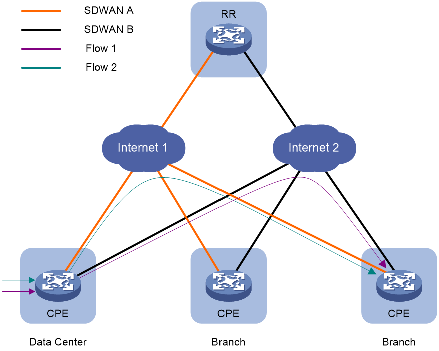
You can use RIR in software-defined WAN (SDWAN) networks.
An SDWAN network involves the following device roles:
· CPE—Endpoint device of the SDWAN tunnel at the user end.
· RR—Route reflector that reflects network and routing information transmitted between CPEs.
All SDWAN device roles support RIR.
As shown in Figure 1, based on link preference, link quality, and link bandwidth, RIR can select SDWAN tunnels to transmit various service flows among the SDWAN devices.
Figure 1 RIR-SDWAN application scenario
Flow template
A flow template defines link selection policies for a type of service flow. A flow ID uniquely identifies a flow template.
The device applies the link selection policies under a flow template to the service flow marked with the flow ID of the flow template.
The device supports using QoS policies to mark flow IDs for service flows. After QoS identifies the service of a packet based on the quintuple and DSCP of the packet, it assigns a flow ID to the packet. Then, RIR will perform link selection for the packet based on the flow template that uses the flow ID.
The flow ID is marked only in the RIR process, and it will not be added to any outgoing packets.
For more information about QoS marking, see QoS overview, QoS policies, and marking configuration in ACL and QoS Configuration Guide.
Link types
RIR-SDWAN link types
RIR-SDWAN links are SDWAN tunnels. Each SDWAN tunnel is attached to a transport network, and is uniquely identified by the transport network name or ID (unique to the transport network). RIR-SDWAN uses the transport network names used by SDWAN tunnels to distinguish links.
An SDWAN tunnel can connect an SDWAN device to multiple SDWAN devices through virtual connections. Two SDWAN devices exchange Transport Tunnel Endpoint (TTE) information (including site ID, device ID, and interface ID) for establishing an SDWAN tunnel between them. As shown in Figure 2, RR establishes two SDWAN tunnels over TN 1 and TN 2 to CPE.
Figure 2 Links in an RIR-SDWAN network
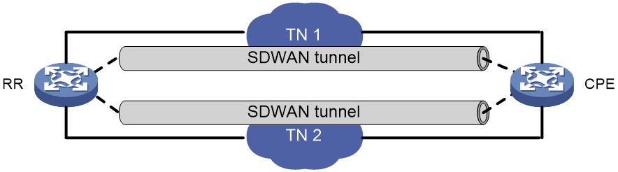
For more information about SDWAN tunnels, see SDWAN Configuration Guide.
Preference-based link selection
Link preference
You can assign a preference to a link based on factors such as the service requirements, the link conditions, and the link cost. RIR preferentially selects links with higher preference.
RIR-SDWAN supports assigning a link preference to an SDWAN tunnel by its transport network name in flow template view.
Link selection rules
You can assign the same preference value to different links in the same flow template.
RIR selects a link for a type of service flows from the links in the flow template in descending order of link preference. If the links with the highest preference cannot meet the service requirements, RIR tries the links with the second highest preference, and so forth to the links with the lowest preference.
If the flow template has two or more links with the same preference, RIR performs link selection based on RIR link load sharing criteria.
Quality-based link selection (RIR-SDWAN)
RIR-SDWAN quality detection mechanisms
RIR-SDWAN defines two link detection mechanisms:
· Keepalive link connectivity probe operation—Uses keepalive packets to check the connectivity of each TTE connection.
· iNQA link quality probe operation—Uses iNQA to measure the latency, jitter, and packet loss rate of each link.
RIR-SDWAN uses the same parameters to probe link connectivity and link quality of all SDWAN tunnels.
RIR-SDWAN quality evaluation mechanism and quality policy
RIR-SDWAN performs quality evaluation based on SLA. An SLA contains a set of link quality evaluation thresholds, including the link delay threshold, jitter threshold, and packet loss threshold. Because the same quality probe parameters apply to all service flows, the SLA determines the quality policy of the flow template.
RIR-SDWAN computes Comprehensive Quality Indicator (CQI) values to evaluate link quality.
· If the probe result of a metric (delay, jitter, or packet loss rate) is lower than or equal to the associated quality threshold in the SLA, the CQI value for the metric is 100.
· If the probe result of a metric is higher than the associated quality threshold in the SLA, the CQI value for the metric is calculated with the formula: (metric threshold × 100) / probe result of the metric.
· The overall CQI value is calculated with the formula: (x × Ds+ y × Js + z × Ls) / (x + y + z).
In this formula, x, y, and z represent the weight values of delay, jitter, and packet loss rate, respectively (the weight values are in the range of 0 to 10, and cannot be all 0). Ds, Js, and Ls represent the CQI values for delay, jitter, and packet loss rate.
To avoid frequent link switchovers, the device uses the approximate overall CQI value to evaluate link quality. The approximate overall CQI value is a multiple of 5 that is smaller than and closest to the overall CQI value. For example, if the overall CQI value is 82.5, the approximate overall CQI value is 80.
If you configure a quality policy for a specific type of service flows, the SDWAN device obtains the link quality result based on the link probe result and SLA. Then it performs quality-based link selection based on the quality result. The device determines the quality of a candidate link for service flows as follows:
· If the approximate overall CQI value is smaller than 100, the link does not meet the service quality requirements.
· If the approximate overall CQI value is equal to 100, the link meets the service quality requirements.
If no quality policy is configured for the service flows, link quality is not considered in link selection, and the link meets the service quality requirements.
Bandwidth-based link selection
About bandwidth-based link selection
Bandwidth-based link selection not only can select links that meet the service bandwidth requirements, but also can load share service traffic among multiple links. This manner can avoid a link from being overwhelmed or congested.
Bandwidth-based link selection policy
The device can select a suitable link for service traffic based on the following bandwidths:
· The used bandwidth of the link or the attached output interface.
· The total bandwidth of the link or the attached output interface.
· The per-session expected bandwidth.
In SDWAN networks, the bandwidth of a link refers to the bandwidth of the attached tunnel interface. The bandwidth of the link-attached output interface refers to the bandwidth of the output interface that sends tunneled packets. The per-session expected bandwidth can be obtained in real time (bandwidth for service flows on a tunnel interface divided by the number of sessions for service flows on the tunnel interface) or manually configured.
The device uses sessions as the minimum granularity and performs bandwidth-based link selection to achieve refined link bandwidth management. A session is uniquely defined by a quintuple including the source IP address, destination IP address, source port, destination port, and transport layer protocol.
When the device selects links for traffic of a session, it first performs bandwidth detection based on the per-session expected bandwidth in the flow template to which the session belongs. A link is qualified in the bandwidth detection if it meets the following requirements:
· For the link-attached output interface, the used bandwidth plus the per-session expected bandwidth is less than 80% of the total bandwidth.
· For the link, the used bandwidth plus the per-session expected bandwidth is less than 80% of the total bandwidth.
Only RIR-SDWAN supports obtaining the per-session expected bandwidth in real time.
Load balancing
Load balancing modes
If multiple links are available for sessions that match a flow template, the device distributes the traffic of the sessions to these links for load balancing based on the link bandwidths. RIR supports the following load balancing modes:
· Per-session weight-based link selection mode—RIR global link load balancing mode that takes effect on all RIR flows. This mode can distribute the sessions that match the same flow template to different links according to the weights of the links. RIR selects only one link to transmit a session.
· Per-session periodic link adjustment mode—RIR global link load balancing mode that takes effect on all RIR flows. This mode not only can distribute the sessions that match the same flow template to different links, but also can periodically adjust links for the sessions. Within one adjustment period, RIR selects only one link to transmit a session.
· Per-packet mode—Flow-specific link load balancing mode that takes effect only on traffic that matches the flow template where this mode is enabled. This mode can distribute the same session to different links for transmission.
The per-packet mode takes precedence over the per-session modes.
Load balancing concepts
Bandwidth weight
The bandwidth of a link is used as the weight of the link. The bandwidth of the link-attached output interface is used as the weight of the output interface. If the total bandwidth is used as the weight, the weight is called the total bandwidth weight. If the remaining bandwidth is used as the weight, the weight is called the remaining bandwidth weight.
For link selection by bandwidth weight, the probability that a link is selected equals the ratio of the link bandwidth to the bandwidth sum of all links. The bandwidth sum of all links is used as the weight sum.
For output interface selection by bandwidth weight, the probability that an interface is selected equals the ratio of the interface bandwidth to the bandwidth sum of all interfaces. The bandwidth sum of all output interfaces is used as the weight sum.
For example, the total bandwidths of links 1, 2, and 3 are 10 Mbps, 10 Mbps, and 20 Mbps, respectively. The remaining bandwidths of links 1, 2, and 3 are 8 Mbps, 4 Mbps, and 8 Mbps, respectively. All the links meet the service requirements. For link selection by total bandwidth weight, the probabilities that links 1, 2, and 3 are selected are 25%, 25%, and 50%, respectively. For link selection by remaining bandwidth weight, the probabilities that links 1, 2, and 3 are selected are 40%, 20%, and 40% ,respectively.
Remaining bandwidth ratio
The remaining bandwidth ratio of a link refers to the ratio of the remaining bandwidth to the total bandwidth of the link.
The remaining bandwidth ratio of a link-attached output interface refers to the ratio of the remaining bandwidth to the total bandwidth of the interface.
A link-attached output interface might have the largest or smallest remaining bandwidth ratio among multiple interfaces.
Per-session weight-based link selection mode
The mechanisms of the per-session weight-based link selection mode are as follows:
· For preference-based primary link selection, preference-based backup link selection, and quality tolerant link selection—If multiple links are available (or multiple links have the highest approximate overall CQI value for quality tolerant link selection in RIR-SDWAN), RIR selects one optimal link for each session of the flow template from these links. The process is as follows:
a. RIR selects an output interface based on the remaining bandwidth weight of each output interface. The used bandwidth is the actually used bandwidth plus the per-session expected bandwidth.
b. RIR selects a link available for the selected output interface based on the remaining bandwidth weight of each link. The used bandwidth is the actually used bandwidth plus the per-session expected bandwidth.
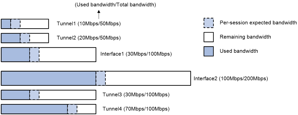
As shown in Figure 3, Interface 1 is the output interface of Tunnel 1 and Tunnel 2, and Interface 2 is the output interface of Tunnel 3 and Tunnel 4. The per-session expected bandwidth is 10 Mbps for Tunnel 1, Tunnel 2, Tunnel 3, and Tunnel 4. With the per-session expected bandwidth added to the used bandwidth of the tunnels, the bandwidth usage values of Tunnel 1, Tunnel 2, Tunnel 3, and Tunnel 4 are 40%, 60%, 40%, and 80%, respectively. Tunnel 1, Tunnel 2, and Tunnel 3 are selectable. Tunnel 4 is not selectable because its bandwidth usage is equal to or greater than 80%.
For the output interfaces attached to the selectable tunnels, RIR adds the per-session expected bandwidth to the used bandwidth for them. The remaining bandwidths of Interface 1 and Interface 2 become 60 Mbps and 90 Mbps, respectively. The selection probabilities for Interface 1 and Interface 2 are 40% and 60%, respectively.
¡ If Interface 1 is selected, the remaining bandwidths of Tunnel 1 and Tunnel 2 are 30 Mbps and 20 Mbps, respectively. The selection probabilities for Tunnel 1 and Tunnel 2 are 60% and 40%, respectively.
¡ If Interface 2 is selected, the selection probability for Tunnel 3 is 100%.
In conclusion, the selection probabilities for Tunnel 1, Tunnel 2, Tunnel 3, and Tunnel 4 are 24%, 16%, 60%, and 0%, respectively.
Figure 3 Per-session weight-based link selection mode
· For bandwidth tolerant link selection—If multiple links are available in a flow template, RIR selects one optimal link for each session of the flow template from these links. In this scenario, RIR performs link selection based on the total bandwidth weight of each link.
For more information about the preference-based primary or backup link selection, quality tolerant link selection, and bandwidth tolerant link selection, see "RIR working mechanisms."
Per-session periodic link adjustment mode
The mechanisms of the per-session periodic link adjustment mode are as follows:
· For preference-based primary link selection, preference-based backup link selection, and quality tolerant link selection—If multiple links are available (or multiple links have the highest approximate overall CQI value for quality tolerant link selection in RIR-SDWAN), RIR selects one optimal link for each session of the flow template from these links. The process is as follows:
a. RIR selects the output interface with the lowest bandwidth usage for a session. The used bandwidth is the actually used bandwidth plus the per-session expected bandwidth.
b. RIR selects a link among the links available for the selected output interface by comparing the bandwidth usage of the links. The link with the lowest bandwidth usage is selected as the optimal link. The used bandwidth is the actually used bandwidth plus the per-session expected bandwidth.
· For bandwidth tolerant link selection—If multiple links meet the requirements of a flow template, RIR selects one optimal link for each session of the flow template from these links. The link selected the last time for a session takes precedence over the other links for that session. If RIR performs link selection for a session for the first time, it uses the following process:
a. Selects an output interface based on the remaining bandwidth weights of the available output interfaces.
b. Selects a link among the links available for the selected output interface based on the remaining bandwidth weights of the links.
The per-session expected bandwidth is added to the used bandwidth.
In per-session periodic link adjustment mode, the device periodically detects the bandwidth usage of output interfaces for all links that have RIR sessions at the configured adjustment intervals. RIR reselect links for sessions that match a flow template if the pyhsical output interfaces for the links in the flow template meet the following requirements: The difference between the largest remaining bandwidth ratio and smallest remaining bandwidth ratio of the output interfaces becomes larger than or equal to the periodic adjustment upper threshold. The link adjustment might be last for several adjustment intervals. RIR stops link adjustment if one of the following requirements is met:
· The difference between the largest remaining bandwidth ratio and the smallest remaining bandwidth ratio of the output interfaces becomes smaller than the periodic adjustment lower threshold.
· The adjustment interval is the 20th interval after link reselection is triggered.
Per-packet mode
The mechanisms of the per-packet mode are as follows:
· For preference-based primary link selection, preference-based backup link selection, and quality tolerant link selection—If multiple links are available (or multiple links have the highest approximate overall CQI value for quality tolerant link selection in RIR-SDWAN), all these links are candidate optimal links for this session. When forwarding traffic for the session, the device distributes the traffic to these links packet by packet. The probability that a link is selected is calculated as follows:
a. RIR compares the link bandwidth and link-associated physical interface bandwidth, and takes the smaller bandwidth value.
b. If the link bandwidth value is smaller, RIR can select a link as the optimal link based on the remaining link bandwidth weight. (The used link bandwidth includes the per-session expected bandwidth.)
c. If the link-associated physical interface bandwidth value is smaller, RIR can select a physical interface based on the remaining bandwidth weight of available link-associated physical interfaces. (The used physical interface bandwidth includes the per-session expected bandwidth.)
· For bandwidth tolerant link selection—If multiple links are available for a session, all these links are candidate optimal links for this session. When forwarding traffic for the session, the device distributes the traffic to these links packet by packet. Each link has the same probability to be selected.
Link selection delay and suppression
To improve packet forwarding efficiency, the device does not repeatedly perform link selection for traffic of the same session. After the device performs link selection for traffic of a session, it forwards the subsequent traffic of that session according to the previous link selection result. Link reselection is triggered when any link in the session's flow template has one of the following changes:
· The quality of a link becomes qualified from unqualified or the quality of a link becomes unqualified from qualified.
· The bandwidth usage of a link has reached 90% of the maximum bandwidth.
· The bandwidth usage of a link-attached output interface has reached 90% of the maximum bandwidth.
To avoid frequent link selection caused by link flapping, RIR defines a link selection delay and link selection suppression period.
After the device performs link selection, it starts the link selection suppression period if the period has been configured. Within the link selection suppression period, the device does not perform link reselection, but it maintains the link state data. When the link selection suppression period ends, the link selection delay timer starts. If the link state still meets the conditions that can trigger link reselection when the delay timer expires, the device performs link reselection. If the link state changes to not meet the conditions that can trigger link reselection within the delay time, the device does not perform link reselection.
RIR working mechanisms
Preparation
RIR-SDWAN preparation
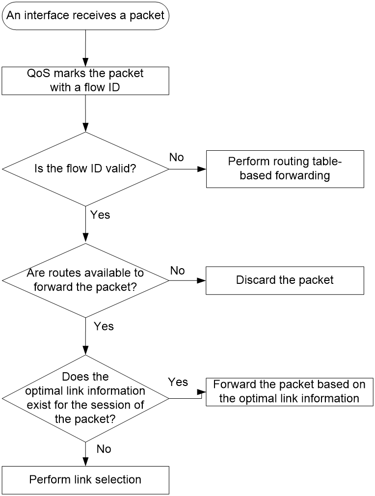
When the device receives a packet on an interface, it handles the packet as follows:
1. Uses QoS to mark the packet with a flow ID based on the quintuple and DSCP of the packet.
2. Identifies whether the flow ID of the packet is valid.
¡ If the flow ID is invalid, the device performs routing table-based forwarding for the packet.
¡ If the flow ID is valid, the device performs the next step.
3. Performs a routing table lookup to identify whether routes are available to forward the packet.
¡ If no route is available, the device discards the packet.
¡ If routes are available, the device performs the next step.
4. Examines whether the optimal link information exists for the session of the packet.
¡ If the optimal link information exists, the device forwards the packet based on the information.
¡ If no optimal link information exists, the device performs link selection for the packet.
Figure 4 RIR-SDWAN preparation
Link selection workflow summary
RIR uses the following workflow to select a link to forward a packet:
1. Selects the flow template that has the same flow ID as the packet.
2. Selects the most suitable link from the links in the flow template by using the following criteria in order:
a. Preference-based primary link selection.
b. Quality tolerant link selection.
c. Bandwidth tolerant link selection.
3. If a link is found suitable, RIR returns the link selection result and stops searching other links. If no link is found suitable for a criterion, RIR uses the next criterion to select links. If RIR fails to find a suitable link by using all criteria, it determines that no link is suitable and returns the link selection result.
4. If no suitable link is found, the device performs forwarding based on the routing table. If a suitable link is found, RIR forwards the packet based on the link selection result.
¡ For RIR-SDWAN, the device directly forwards the packet through the link.
After finishing link selection, the device associates the quintuple of the packet with the most suitable link and records the association as the optimal link information for the session. The device forwards the subsequent packets of the same session based on the optimal link information. If no traffic is received for the session for a period of time, the device will delete the optimal link information.
Figure 5 RIR link selection workflow

Preference-based primary link selection
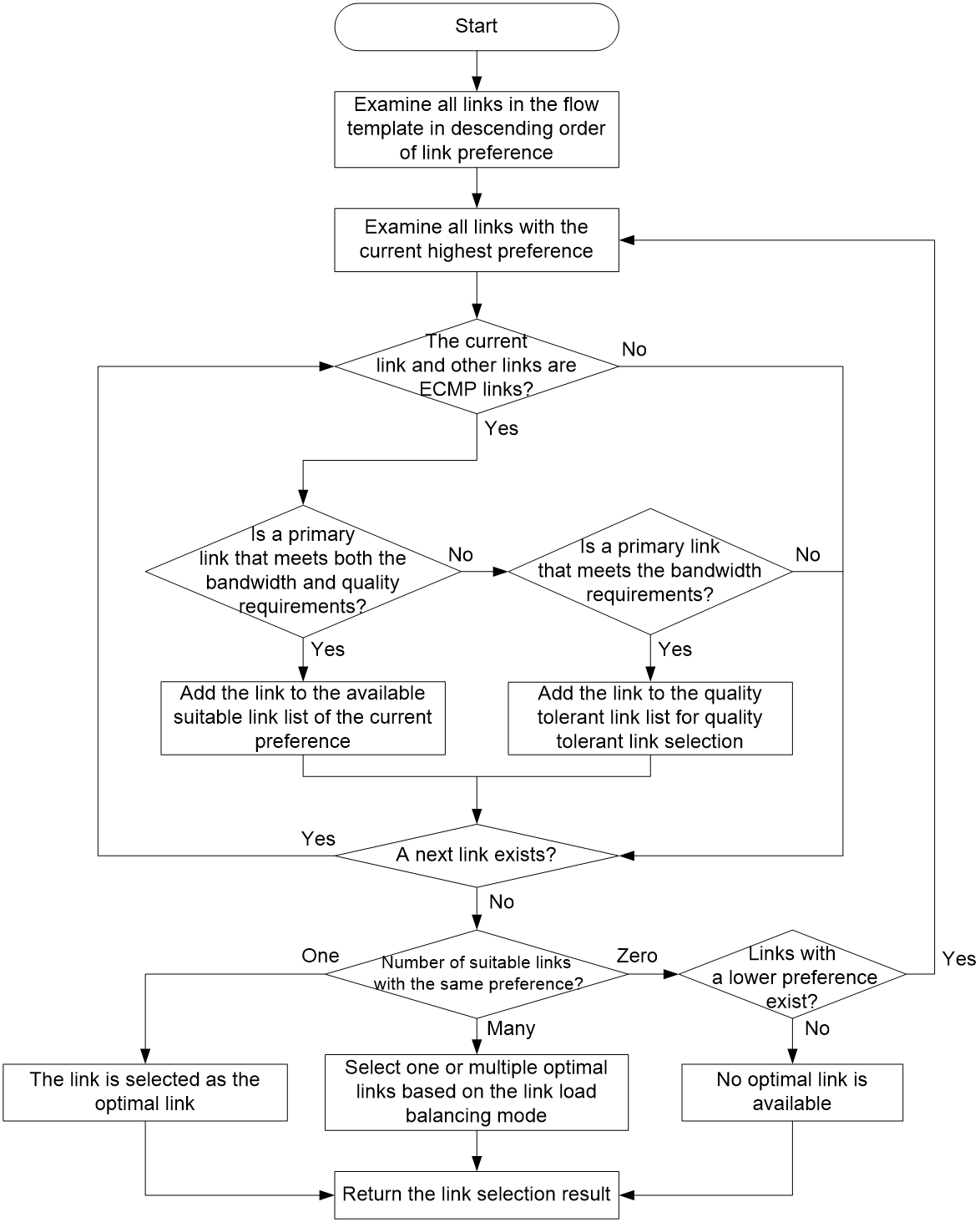
RIR preferentially selects primary links that meet both the quality and bandwidth requirements for a service flow that matches a flow template. As shown in Figure 6, the device selects a primary link from the primary links in the flow template by examining the links in descending order of link preference. The device uses the following process to examine links with the same preference:
1. The device examines all links with the preference and identifies whether a link forms ECMP routes with other links. If a link forms ECMP routes with other links, the device further identifies whether the link is a primary link that meets both the quality and bandwidth requirements of the service.
¡ If yes, the device adds the link to the available suitable link list of that preference.
¡ If no, the device further identifies whether the link is a primary link that meets the bandwidth requirements of the service.
- If yes, the device adds the link to the quality tolerant link list for quality tolerant link selection. Then, the device continues to examine other links with the same preference.
- If no, the device continues to examine other links with the same preference.
If a link does not form ECMP routes with other links, the device continues to examine other links with the same preference.
2. When the device finishes examining all links with the preference, it identifies how many suitable links are available for the service flow.
¡ If only one suitable link is available, the device selects that link as the optimal link.
¡ If multiple suitable links are available, the device selects one or multiple optimal links from them based on the link load balancing mode. In a per-session load balancing mode, the device selects only one link as the optimal link of a session. In the per-packet load balancing mode, the device can select multiple links as the optimal links of a session.
¡ If no suitable link is available, the device examines the links that have a preference value lower than the links with the current preference.
If no primary links in the flow template are suitable, the device determines that no optimal primary link is found for the service flow.
For more information about identifying whether a link meets the quality requirements, see "RIR-SDWAN quality evaluation mechanism and quality policy." For more information about identifying whether a link meets the bandwidth requirements, see "Bandwidth-based link selection."
Figure 6 Preference-based primary link selection workflow
Quality tolerant link selection
If preference-based primary link selection fails to select a suitable link, the device performs quality tolerant link selection.
The links that meet the quality tolerant link selection criterion are those added to the quality tolerant link list during preference-based primary link selection. These links do not meet the quality requirements of the service, but they meet the bandwidth requirements of the service. Quality tolerant link selection selects a link from the links that meet only the bandwidth requirements of the service.
· RIR-SDWAN quality tolerant link selection—The device selects the link with the highest approximate overall CQI value as the optimal link. If multiple links have the highest approximate overall CQI value, the device selects one or multiple optimal links from them based on the link load balancing mode.
Bandwidth tolerant link selection
If quality tolerant link selection still cannot find a suitable link for a service flow, the device performs bandwidth tolerant link selection. Bandwidth tolerant link selection selects one link from ECMP routes in the flow template as the optimal link.
If multiple links are available, the device selects one or multiple optimal links from them based on the link load balancing mode.
Restrictions and guidelines: RIR configuration
When a link has a large amount of traffic, do not change the link selection policy for that link. For example, change the link preference. If you change the link selection policy, the system might fail to perform link selection as expected. As a best practice, change the link selection policy for a link when the link does not have traffic or when the link has a small amount of traffic.
RIR-SDWAN tasks at a glance
To configure RIR-SDWAN, perform the following tasks:
1. Enabling the RIR-SDWAN service
2. Configuring the link probe feature on an SDWAN device
¡ Configuring the link connectivity probe feature
¡ Configuring the link quality probe feature
3. Configuring an SLA (RIR-SDWAN)
4. Configuring link attributes
¡ Configuring the transport network of a link
¡ Configuring the link bandwidth of a tunnel interface
¡ Specifying an output interface for a link
5. Configuring a flow template
¡ Configuring a quality policy for the flow template
¡ Configuring the CQI parameters
¡ (Optional.) Specifying the per-session expected bandwidth
¡ Specifying link preference values for links
¡ Discarding the specified service flow upon failure to find the optimal link
¡ Enabling preferred selection for the links of the same transport network
6. (Optional.) Enabling the link bandwidth consideration feature during link selection
7. (Optional.) Enabling the service switchback feature
8. (Optional.) Configuring the link load balancing mode
¡ Setting the per-session periodic link adjustment mode
¡ Setting the per-packet load balancing mode
By default, the link load balancing mode is per-session weight-based link selection mode.
9. (Optional.) Configuring flow priority-based traffic scheduling
10. (Optional.) Setting the link selection delay and link selection suppression period
11. Configuring a QoS policy to mark matching packets with a flow ID
¡ Creating a traffic class and defining packet match criteria
¡ Creating a traffic behavior and configuring a flow ID marking action
¡ Applying the QoS policy to an interface
12. (Optional.) Configuring RIR collaboration (RIR-SDWAN)
a. Establishing RIR collaboration relationship with the specified peer device
b. Associating the local SDWAN extended tunnel interface with the peer SDWAN tunnel interface
d. Configuring the redirect address for RIR data packets
e. Configuring the collaboration group ID for an interface
13. (Optional.) Maintaining RIR-SDWAN
¡ Configuring application quality probing
¡ Configuring flow ID-based traffic rate statistics for tunnels
Enabling the RIR service
About the RIR service
You can deploy RIR based on SDWAN tunnels.
For RIR-SDWAN, you must enable the RIR-SDWAN service on SDWAN devices.
Restrictions and guidelines for enabling the RIR service
When you enable the RIR-SDWAN service, the system enables the RIR process. When you disable the RIR-SDWAN service, the system disables the RIR process.
Enabling the RIR-SDWAN service
1. Enter system view.
system-view
2. Enable the RIR-SDWAN service and enter RIR-SDWAN view.
rir sdwan
By default, the RIR-SDWAN service is disabled.
Configuring the link probe feature on an SDWAN device
Configuring the link connectivity probe feature
About this task
The device starts sending keepalive requests to the peer at the specified intervals, and waits for receiving keepalive responses after the SDWAN keepalive feature is enabled. If the device cannot receive keepalive responses within the keepalive interval multiplied by keepalive retries, it determines that the TTE connection is unreachable to the peer device. The device no longer forwards packets through the TTE connection.
After you enable the RIR-SDWAN service, the device reports the TTE connection status detected through the SDWAN keepalive feature to RIR as a link selection criteria.
Restrictions and guidelines
As a best practice in an RIR-SDWAN network, set the keepalive interval in the range of 1 to 5 seconds.
Procedure
1. Enter system view.
system-view
2. Create an SDWAN tunnel interface in UDP encapsulation mode and enter tunnel interface view.
interface tunnel tunnel-number mode sdwan udp [ ipv6 ]
For packet tunneling to succeed, the two ends of a tunnel must use the same tunnel mode.
3. (Optional.) Configure the keepalive interval and number of keepalive retries for the SDWAN tunnel.
sdwan keepalive interval interval [ retry retries ]
By default, the keepalive interval is 10 seconds and the number of keepalive retries is 3.
For more information about this command, see SDWAN Command Reference.
Configuring the link quality probe feature
About this task
After you enable the RIR-SDWAN service, the device uses iNQA to periodically probe link quality of all SDWAN tunnels, and performs link selection based on the probe result.
Prerequisites
Before performing this task, configure NTP or PTP to synchronize the clock between the analyzer and all collectors. For more information about NTP and PTP, see Network Management and Monitoring Configuration Guide.
Enable the iNQA analyzer functionality on any SDWAN device in the SDWAN network, and configure the analyzer ID.
Procedure
1. Enter system view.
system-view
2. Enable the collector functionality and enter its view.
inqa collector
By default, the collector functionality is disabled.
For more information about this command, see Network Management and Monitoring Command Reference.
3. Bind an analyzer to the collector.
analyzer analyzer-id
By default, no analyzer is bound to a collector.
For more information about this command, see Network Management and Monitoring Command Reference.
4. Return to system view.
quit
5. Enter RIR-SDWAN view.
rir sdwan
6. Configure the link quality probe interval.
link-quality probe interval interval
By default, the link quality probe interval is 60 seconds.
If you modify the link quality probe interval, the device stops probing the quality of all SDWAN tunnels, and uses the new interval to start probing the link quality of all SDWAN tunnels.
Configuring an SLA
Configuring an SLA (RIR-SDWAN)
About this task
In an SDWAN network, an SDWAN device requires specifying only an SLA for the quality policy in the flow template.
Perform this task to create an SLA and configure associated parameters on the SDWAN device.
Procedure
1. Enter system view.
system-view
2. Enter RIR-SDWAN view.
rir sdwan
3. Create an SLA and enter its view.
sla sla-id
4. Configure the link delay threshold.
delay threshold threshold-value
By default, the link delay threshold is 10 milliseconds.
5. Configure the link jitter threshold.
jitter threshold threshold-value
By default, the link jitter threshold is 100 milliseconds.
6. Configure the packet loss threshold.
packet-loss threshold threshold-value
By default, the packet loss threshold is 100‰.
Configuring link attributes
Configuring the transport network of a link
About this task
RIR-SDWAN uses transport network names used by SDWAN tunnels to distinguish links.
Procedure
1. Enter system view.
system-view
2. Enter SDWAN tunnel interface view.
interface tunnel tunnel-number mode sdwan udp
3. Configure the transport network for the link.
sdwan transport-network network-name id network-id
By default, no transport network is configured for an SDWAN tunnel.
For more information about this command, see SDWAN Command Reference.
Configuring the link bandwidth of a tunnel interface
1. Enter system view.
system-view
2. Enter SDWAN tunnel interface view.
interface tunnel tunnel-number mode { sdwan udp }
3. Configure the expected link bandwidth of the tunnel interface.
bandwidth bandwidth-value
The default expected bandwidth (in kbps) is the interface maximum rate divided by 1000.
The expected bandwidth is an informational parameter used only by higher-layer protocols for calculation. You cannot adjust the actual bandwidth of an interface by using this command.
For more information about this command, see tunneling commands in Layer 3—IP Services Command Reference.
Specifying an output interface for a link
About this task
Use this feature to specify an output interface for tunneled packets on a link. With this feature, RIR uses the bandwidth usage of both the SDWAN tunnel interface and the output interface to determine the link selection result.
Restrictions and guidelines
You must specify the physical interface through which tunneled packets are forwarded to the VXLAN or SDWAN tunnel.
If you specify the IP address of a physical interface as the tunnel source address, you must specify that physical interface as the output interface for tunneled packets.
You can specify only one output interface for an SDWAN tunnel. However, you can specify the same output interface for multiple SDWAN tunnels.
For RIR-SDWAN, the output interfaces can be Ethernet interfaces, Ethernet subinterfaces, Ethernet channel interfaces on 4G/5G Modem modules, Layer 3 aggregate interfaces, or tunnel interfaces.
If an Ethernet subinterface is specified as the output interface on an SDWAN tunnel interface, you must execute the sub-interface rate-statistic command on the main interface of the subinterface. This command enables rate statistics collection for the subinterfaces of an Ethernet interface. If you do not execute this command, RIR might fail to select the optimal link because of inaccurate rate statistics.
Procedure
1. Enter system view.
system-view
2. Enter SDWAN tunnel interface view.
interface tunnel tunnel-number mode { sdwan udp }
3. Specify an output interface for tunneled packets.
tunnel out-interface interface-type interface-number
By default, no output interface is specified for tunneled packets on a tunnel interface.
For more information about this command, see tunneling commands in Layer 3—IP Services Command Reference.
Specifying a dedicated link for a service flow
About this task
When the device intelligently selects links for the service traffic, it preferentially selects the dedicated link for that traffic.
· If only one dedicated link is available for the service traffic, the link is selected for forwarding.
· If multiple dedicated links are available for the service traffic, the device selects the one with the highest preference for forwarding. If multiple dedicated links with the same preference exist, the device load shares service traffic on these links according to the load sharing mode.
· If none of the dedicated links are available for the traffic, the device selects the optimal link from the flow template for forwarding.
When the device selects the dedicated link for the service traffic, it also schedules other service traffic to other links. If the device cannot select another link other than the dedicated link for other service traffic, it drops other service traffic packets to ensure traffic stability on the dedicated link. When the service traffic no longer uses the dedicated link, the device can reschedule other service traffic to the dedicated link.
Restrictions and guidelines
· The dedicated link must already exist in the associated flow template. If the link is not configured for the flow template, the device does not take that link as a dedicated link during link selection for the service traffic.
· You can configure a tunnel as a dedicated link for only one type of service traffic, and configure multiple dedicated links for the same type of service traffic.
· If the link load sharing mode for specific service traffic is per-packet mode, the dedicated link configured for the service traffic does not take effect.
Procedure
1. Enter system view.
system-view
2. Enter SDWAN tunnel interface view.
interface tunnel tunnel-number mode sdwan
3. Specify the tunnel as the dedicated link for the specified service flow.
rir dedicated flow flow-id
By default, the tunnel is not the dedicated link for the service flow.
Configuring a flow template
About flow template configuration
Configure a flow template to determine the link selection policies for a type of service flow.
Creating a flow template
About this task
To define link selection policies for a type of service flow, you can create a flow template and configure link selection policies in the flow template. By marking the type of service flow with the flow ID of the flow template, the device can use the link selection policies in the flow template to select links for that type of service flow.
Procedure (RIR-SDWAN)
1. Enter system view.
system-view
2. Enter RIR-SDWAN view.
rir sdwan
3. Create a flow template and enter RIR-SDWAN flow template view.
flow flow-id
Configuring a quality policy for the flow template
About this task
For RIR-SDWAN, the quality policy of a flow template is determined by the SLA.
Procedure (RIR-SDWAN)
1. Enter system view.
system-view
2. Enter RIR-SDWAN view.
rir sdwan
3. Enter RIR-SDWAN flow template view.
flow flow-id
4. Configure a quality policy for the flow template.
quality-policy sla sla-id
By default, no quality policy is configured for a flow template.
The specified SLA must already exist.
Configuring the CQI parameters
About this task
RIR-SDWAN computes CQI values to evaluate link quality. Perform this task to configure the weights for the delay, jitter, and packet loss metrics used for computing CQI values.
Restrictions and guidelines
The weights for the delay, jitter, and packet loss metrics cannot be all 0.
Procedure
1. Enter system view.
system-view
2. Enter RIR-SDWAN view.
rir sdwan
3. Enter RIR-SDWAN flow template view.
flow flow-id
4. Configure the weights for the delay, jitter, and packet loss metrics used for computing CQI values.
cqi-weight delay delay-weight jitter jitter-weight packet-loss packet-loss-weight
By default, the weights for the delay, jitter, and packet loss metrics are all 1.
Specifying the per-session expected bandwidth
About this task
The device obtains the per-session expected bandwidth in real time, and performs bandwidth detection based on the obtained bandwidth. If the device fails to obtain the bandwidth, it performs bandwidth detection based on the per-session expected bandwidth in the flow template to which the session belongs. A link is qualified in the bandwidth detection if it meets the following requirements:
· For the link-attached output interface, the used bandwidth plus the per-session expected bandwidth is less than 80% of the total bandwidth.
· For the link, the used bandwidth plus the per-session expected bandwidth is less than 80% of the total bandwidth.
Restrictions and guidelines
Only RIR-SDWAN supports obtaining the per-session expected bandwidth in real time.
The per-packet load balancing mode requires manually configuring the per-session expected bandwidth.
Procedure (RIR-SDWAN)
1. Enter system view.
system-view
2. Enter RIR-SDWAN view.
rir sdwan
3. Enter RIR-SDWAN flow template view.
flow flow-id
4. Specify the per-session expected bandwidth.
expect-bandwidth bandwidth
By default, the per-session expected bandwidth is 0 kbps.
Specifying link preference values for links
About this task
RIR preferentially selects links with higher preference for a type of service flow.
RIR-SDWAN supports assigning a link preference to an SDWAN tunnel by its transport network name in flow template view.
Restrictions and guidelines
You can assign the same link preference value to different links in the same flow template.
Procedure (RIR-SDWAN)
1. Enter system view.
system-view
2. Enter RIR-SDWAN view.
rir sdwan
3. Enter RIR-SDWAN flow template view.
flow flow-id
4. Configure a link preference.
path sdwan transport-network network-name [ group-id group-id ] preference preference
By default, no link preference is configured in a flow template.
Discarding the specified service flow upon failure to find the optimal link
About this task
With the RIR link selection mechanism, the device can select the optimal link from the links of the associated flow template to forward the service flow. If the optimal link is not found, the device forwards the service flow according to routing table lookup. If all links specified for a specific service fail, you can configure this feature to not assign the service flow to other links. For example, you can configure this feature to not assign low-priority video traffic to service links. With this feature configured, if the device fails to find the optimal link for the service flow, it discards the packets for that service flow.
Procedure
1. Enter system view.
system-view
2. Enter RIR view.
rir
3. Enter flow template view.
flow flow-id
4. Enable the device to discard the service flow upon failure to find the optimal link.
no-optimal-link drop
By default, the device forwards the specified service flow according to routing table lookup upon failure to find the optimal link.
Enabling preferred selection for the links of the same transport network
About this task
With preferred selection enabled for the links of the same transport network, the device preferentially selects a TTE connection with the same transport network ID for packet forwarding. If none of the TTE connections with the same transport network ID meet the link selection conditions, the device selects links from the TTE connections with a different transport network ID. If multiple TTE connections with the same transport network ID exist, they load share traffic based on the link selection principles.
Procedure
1. Enter system view.
system-view
2. Enter RIR-SDWAN view.
rir sdwan
3. Enter RIR-SDWAN flow template view.
flow flow-id
4. Enable preferred selection for the links of the same transport network.
link-select same-transport-network prefer
By default, preferred selection is disabled for the links of the same transport network.
Enabling the link bandwidth consideration feature during link selection
About this task
If you are concerned about the forwarding path of service traffic and not concerned about link quality and bandwidth, you can perform this task to disable the link bandwidth consideration feature during link selection.
Procedure
1. Enter system view.
system-view
2. Enter RIR-SDWAN view.
rir sdwan
3. Disable the link bandwidth consideration feature during link selection.
link-bandwidth ignore
By default, the link bandwidth is considered during link selection.
Enabling the service switchback feature
About this task
In the RIR-SDWAN network, with the service switchback feature enabled, the device periodically checks (at intervals of 60 seconds) for a link with higher preference that meets the quality-based and bandwidth-based link selection policies. (The interval is more than 60 seconds for distributed devices and RIR collaboration devices). When such a link is available and its bandwidth usage is less than the configured service switchback bandwidth threshold, the device switches service traffic from the current link back to the link with higher preference. This ensures that traffic is forwarded through the optimal link.
Procedure
1. Enter system view.
system-view
2. Enter RIR-SDWAN view.
rir sdwan
3. Configure the service switchback bandwidth threshold.
switch-back bandwidth-threshold threshold-value
By default, the service switchback bandwidth threshold is 70%
4. Enable the service switchback feature.
switch-back enable
By default, the service switchback feature is disabled.
Configuring the link load balancing mode
Restrictions and guidelines for link load balancing mode configuration
For a flow template, the per-packet load balancing mode takes precedence over the global per-session periodic link adjustment mode. If the per-packet load balancing mode is not enabled for a flow template, the flow template uses the global link load balancing mode.
Setting the per-session periodic link adjustment mode
1. Enter system view.
system-view
2. Enter RIR-SDWAN view.
rir sdwan
3. Set the link load balancing mode to the per-session periodic link adjustment mode.
load-balance per-session periodic-adjust enable
By default, the link load balancing mode is per-session weight-based link selection mode.
4. Set the adjustment interval for the per-session periodic link adjustment mode.
load-balance per-session periodic-adjust adjust-interval interval-value
By default, the adjustment interval for the per-session periodic link adjustment mode is 30 seconds.
5. Set the periodic adjustment thresholds in per-session periodic link adjustment mode.
load-balance per-session periodic-adjust threshold upper upper-threshold-value lower lower-threshold-value
By default, the periodic adjustment upper threshold is 50% and the periodic adjustment lower threshold is 20%.
The periodic adjustment upper threshold must be greater than or equal to the periodic adjustment lower threshold.
Setting the per-packet load balancing mode
Restrictions and guidelines
Because packets of the same session are distributed to multiple links, the receiver might receive out-of-order packets. As a best practice, do not enable per-packet load balancing for order-sensitive services (except the services that use protocols to maintain a correct packet order, for example, TCP).
If Wide Area Application Services (WAAS) log packet compression or decompression is enabled, per-packet load balancing cannot be performed correctly. For more information about WAAS log packet compression and decompression, see WAAS configuration in Layer 3—IP Services Configuration Guide.
Procedure
1. Enter system view.
system-view
2. Enter RIR-SDWAN view.
rir sdwan
3. Enter RIR-SDWAN flow template view.
flow flow-id
4. Set the link load balancing mode to the per-packet mode.
load-balance per-packet enable
By default, the RIR global link load balancing mode applies.
Configuring flow priority-based traffic scheduling
About this task
To ensure that services with higher priority preferentially use link resources, enable flow priority-based traffic scheduling.
The priority of a flow that matches a flow template is determined by the ID of the SLA associated with that flow template. The greater the SLA ID is, the higher the flow priority. To specify an SLA for a flow template, use the quality-policy command. If the command is not configured in a flow template, flows that match the flow template have the lowest priority.
If flow priority-based traffic scheduling is enabled, traffic scheduling is triggered when the bandwidth usage of a link-attached output interface exceeds the upper threshold. The scheduling might be last for several scheduling periods. Within each scheduling period, RIR redistributes the current lowest priority flow on this link to other links. The scheduling stops for a link in one of the following conditions:
· The bandwidth usage of all link-attached output interfaces for the current lowest priority flow is below the lower threshold.
· Only the highest priority flow is left on this link.
Procedure
1. Enter system view.
system-view
2. Enter RIR-SDWAN view.
rir sdwan
3. Enable flow priority-based traffic scheduling.
flow priority-based-schedule enable
By default, flow priority-based traffic scheduling is disabled.
4. Set the scheduling period for flow priority-based traffic scheduling.
flow priority-based-schedule schedule-period schedule-period-value
By default, the scheduling period for flow priority-based traffic scheduling is 30 seconds.
5. Set the bandwidth usage thresholds for flow priority-based traffic scheduling.
flow priority-based-schedule bandwidth-threshold upper upper-threshold lower lower-threshold
By default, the bandwidth usage upper threshold is 90% and the bandwidth usage lower threshold is 20%.
The upper threshold must be greater than or equal to the lower threshold.
Setting the link selection delay and link selection suppression period
1. Enter system view.
system-view
2. Enter RIR-SDWAN view.
rir sdwan
3. Set the link selection delay.
link-select delay delay
By default, the link selection delay is 60 seconds.
4. Set the link selection suppression period.
link-select suppress-period period-value
By default, no link selection suppression period is configured. The device does not start the link selection suppression period after a link selection.
As a best practice, set the link selection suppression period to a multiple of the link selection delay time. Make sure the suppression period is at least double of the link selection delay time.
Configuring a QoS policy to mark matching packets with a flow ID
About configuring a QoS policy to mark matching packets with a flow ID
Apply a QoS policy to an interface to mark matching packets on the interface with a flow ID. RIR processes packets marked with a flow ID based on the flow template that uses the flow ID. For more information about QoS marking, see QoS overview, QoS policies, and marking configuration in ACL and QoS Configuration Guide.
Creating a traffic class and defining packet match criteria
1. Enter system view.
system-view
2. Create a traffic class and enter its view.
traffic classifier classifier-name [ operator { and | or } ]
3. Define packet match criteria, including the quintuple and DSCP.
if-match [ not ] match-criteria
By default, no packet match criteria are defined.
Creating a traffic behavior and configuring a flow ID marking action
1. Enter system view.
system-view
2. Create a traffic behavior and enter its view.
traffic behavior behavior-name
3. Configure the traffic behavior to mark matching traffic with the specified flow ID.
remark flow-id flow-id
By default, no flow ID marking action is configured.
Configuring a QoS policy
1. Enter system view.
system-view
2. Create a QoS policy and enter its view.
qos policy policy-name
3. Associate the traffic behavior with the traffic class in the QoS policy.
classifier classifier-name behavior behavior-name
By default, no traffic behavior is associated with a traffic class.
Applying the QoS policy to an interface
1. Enter system view.
system-view
2. Enter interface view.
interface interface-type interface-number
3. Apply the QoS policy to the inbound direction of the interface.
qos apply policy policy-name inbound
By default, no QoS policy is applied to an interface.
Configuring RIR collaboration (RIR-SDWAN)
Establishing RIR collaboration relationship with the specified peer device
About this task
Make sure the devices in an RIR collaboration group reside at the same site. Each pair of devices in an RIR collaboration device group must establish RIR collaboration relationship. You must configure this command on both the local and peer devices.
In a pair of devices with RIR collaboration relationship, the device with a lower IP address is the client. The client uses the port number specified by using this command to initiate a TCP connection (collaboration channel) request to its peer. Through the collaboration channel, the local device can synchronize the TTE connection information and RIR link quality information on the specified tunnel interface to the peer device.
Restrictions and guidelines
The local and peer devices must use the same TCP port number for link data synchronization. A device can use the same or different TCP port numbers to synchronize data to different peers.
If you execute this command multiple times for the same pair of devices (with the same local IP address, peer device ID, and peer IP address), the most recent configuration takes effect.
You can configure only one collaboration channel between the local device and peer device. Make sure the both the local and peer devices use the same IP address type.
Procedure
1. Enter system view.
system-view
2. Establish RIR collaboration relationship with the specified peer device.
sdwan collaboration peer device-id device-id [ vpn-instance vpn-instance-name ] { peer-ipv4-address | peer-ipv6-address } local { local-ipv4-address | local-ipv6-address } [ sync-port port-number ]
By default, the local device does not establish RIR collaboration relationship with the peer device.
Associating the local SDWAN extended tunnel interface with the peer SDWAN tunnel interface
About this task
After associating the local SDWAN extended tunnel interface with the peer SDWAN tunnel interface, if the local device forwards data packets through the TTE connection on the peer device, it must complete SDWAN encapsulation locally and use the associated SDWAN extended tunnel interface to forward the data packets to the peer device.
Procedure
1. Enter system view.
system-view
2. Enter GRE-encapsulated SDWAN extended tunnel view.
interface tunnel tunnel-number mode sdwan-ex gre [ ipv6 ]
3. Associate the local SDWAN extended tunnel interface with the peer SDWAN tunnel interface.
sdwan collaboration-map peer-device-id device-id peer-interface-id interface-id
By default, the local SDWAN extended tunnel interface is not associated with the peer SDWAN tunnel interface.
Synchronizing TTE connection information and RIR link quality information on the local SDWAN tunnel interface to the peer device through the collaboration channel
About this task
With this command configured, the device synchronizes TTE connection information and RIR link quality information on the local SDWAN tunnel interface to the specified peer device through the collaboration channel.
Procedure
1. Enter system view.
system-view
2. Enter SDWAN tunnel interface view.
interface tunnel tunnel-number mode sdwan udp
3. Synchronize TTE connection information and RIR link quality information on the local SDWAN tunnel interface to the peer device through the collaboration channel.
sdwan collaboration peer-device-id device-id
By default, the device does not synchronize TTE connection information and RIR link quality information on the local SDWAN tunnel interface to the peer device through the collaboration channel.
Configuring the redirect address for RIR data packets
About this task
In the collaboration link selection network, the concept of Owner is introduced to ensure that the same service traffic is forwarded by the same collaboration device. Owner is calculated from the five-tuple of service traffic. If the same service traffic has the same five-tuple, the calculated Owner is also the same, ensuring that the same service traffic is forwarded by the same Owner device. For service traffic that is directly sent to a non-Owner collaboration device, configure this command to redirect the traffic to the collaboration device that acts as the Owner for processing.
Procedure
1. Enter system view.
system-view
2. Configure the redirect address for RIR data packets.
rir redirect peer peer-ipv4-address interface interface-type interface-number
By default, no redirect address is configured for RIR data packets. That is, RIR data packets will not be redirected to the peer device.
Configuring the collaboration group ID for an interface
About this task
In the collaboration link selection network, to forward the same service traffic through the same Owner device, configure the same collaboration group on the interfaces of the devices that establish RIR collaboration relationship for service traffic access. For service traffic that is directly sent to a non-Owner collaboration device, it carries the interface collaboration group ID and is redirected to the collaboration device that acts as the Owner. The Owner device processes the packets according to the service traffic input interface and configures the same interface collaboration group ID for the interface on the local end.
Procedure
1. Enter system view.
system-view
2. Enter interface view.
interface interface-type interface-number
3. Configure the collaboration group ID for the interface.
rir redirect group group-id
By default, no collaboration group ID is configured for the interface.
Configuring the aging timer for the TTE connection synchronized through the collaboration channel upon collaboration channel disconnection
1. Enter system view.
system-view
2. Configuring the aging timer for the TTE connection synchronized through the collaboration channel upon collaboration channel disconnection.
sdwan collaboration tte-connection aging aging-time
By default, the aging timer for the TTE connection synchronized through the collaboration channel upon collaboration channel disconnection is 180 seconds.
Enabling BFD for a tunnel
About this task
Enable BFD for the tunnel to avoid failure of CPE devices for detecting or timely detecting faults in the SDWAN extended tunnel, resulting in packet forwarding failure. This feature needs to be enabled on both CPE devices at both ends of the tunnel. CPE devices periodically send BFD control packets to the collaboration peer devices through the SDWAN extended tunnel. If no BFD control packet is received from the peer end within five seconds, the device sets the tunnel state to Defect. The interface state remains up. After the SDWAN extended tunnel failure is resolved, the tunnel state automatically restores to Up.
Procedure
1. Enter system view.
system-view
2. Enter GRE-encapsulated SDWAN extended tunnel view.
interface tunnel tunnel-number mode sdwan-ex gre [ ipv6 ]
3. Enable BFD for the tunnel.
tunnel bfd enable [ template template-name ]
By default, BFD is disabled for the tunnel.
Configuring application quality probing
About this task
In addition to link quality probing, RIR-SDWAN supports application quality probing. For specific service flows forwarded through the SDWAN tunnels, RIR-SDWAN detects the quality of the application flows with the specified packet signatures.
With this feature enabled, the device uses iNQA to periodically probe the application flows with the specified packet signatures for application quality calculation. The application quality probe result is used for application analysis and does not affect link selection.
Restrictions and guidelines
If application quality probing is enabled, the device does not support the per-packet load balancing mode.
You can specify only one packet signature for an application quality probe instance. To detect applications with multiple packet signatures, create multiple application quality probe instances.
This feature requires creating the same application quality probe instance (with the same name) on two SDWAN devices. In addition, you must specify the instances as the source and destination instances, respectively, and configure the same signature and quality probe interval settings for the instances.
For a specific service flow, the device does not detect the quality of an application flow without any packets matching the specified signature.
To modify the settings of an application quality probe instance, first disable application quality probing for all service flows of the instance.
Prerequisites
Before enabling application quality probing for a service flow, make sure an associated flow template has been created on the device. Without the configuration, application quality probing cannot take effect on the service flow.
Procedure
1. Enter system view.
system-view
2. Enter RIR-SDWAN view.
rir sdwan
3. Enter application quality probe view.
application-quality
4. Create an application quality probe instance and enter application quality probe instance view.
instance instance-name
5. Configure the application quality probe interval.
probe interval interval
By default, the application quality probe interval is 60 seconds.
6. Configure the peer device for application quality probing.
peer { source | destination } site-id site-id device-id device-id
By default, no peer device is configured for application quality probing.
7. Configure the packet signature for application quality probing.
signature { source-ip { any | src-ip-address [ src-mask-length ] } destination-ip { any | dest-ip-address [ dest-mask-length ] } | source-ipv6 { any | src-ipv6-address [ src-prefix-length ] } destination-ipv6 { any | dest-ipv6-address [ dest-prefix-length ] } }
By default, no packet signature is configured for application quality probing.
8. Enable application quality probing for a service flow.
probe flow flow-id
By default, application quality probing is disabled for all service flows.
The device supports enabling application quality probing for multiple service flows in an application quality probe instance.
Enabling RIR logging
About this task
RIR logs record events occurred during the RIR process, such as link selection and reselection, quality change, bandwidth change, configuration change, and link fault events. The logs help the administrator analyze, maintain, and adjust the RIR network.
RIR logs are flow logs. To output RIR logs, you must also configure flow log features. For more information about flow logs, see Network Management and Monitoring Configuration Guide.
Restrictions and guidelines
Flow logs can be load-balanced based on the session source IP, which means that a single flow log will be sent to only one specific log host among all the configured log hosts. However, RIR logs do not support this output method.
Procedure
1. Enter system view.
system-view
2. Enter RIR-SDWAN view.
rir sdwan
3. Enable RIR logging.
log enable
By default, RIR logging is disabled.
Configuring flow ID-based traffic rate statistics for tunnels
About this task
This feature enables the device to periodically collect traffic rate statistics for tunnels on a flow ID basis.
Procedure
1. Enter system view.
system-view
2. Enable flow ID-based traffic rate statistics for tunnels.
tunnel flow-statistics enable
By default, flow ID-based traffic rate statistics for tunnels is disabled.
3. (Optional.) Set the intervals at which the device collects flow ID-based traffic rate statistics for tunnels.
tunnel flow-statistics interval interval
By default, the device collects flow ID-based traffic rate statistics for tunnels at intervals of 300 seconds.
Verifying and maintaining RIR
Verifying RIR configuration and running status
Perform display tasks in any view.
· Display application quality probe information.
display rir sdwan application-quality instance instance-name [ flow-id flow-id ]
· Display bandwidth information for TTE connections.
display rir sdwan bandwidth tte [ peer peer-site-id peer-device-id peer-interface-id [ local local-site-id local-device-id local-interface-id ] ]
· Display bandwidth information for the specified SDWAN tunnel interface and the associated output interface.
display rir sdwan bandwidth tunnel tunnel-number
· Display link selection policy information for the specified service flow.
display rir sdwan flow flow-id
· Display link quality detection information for SDWAN tunnels.
display rir sdwan link-quality [ tunnel tunnel-number ]
· Display service session statistics of the specified tunnel interface.
display rir sdwan session-statistics tunnel interface-number [ flow flow-id ] [ slot slot-number ]
Displaying collaboration channel status and packet statistics
To display collaboration channel status and packet statistics, execute the following command in any view:
display sdwan collaboration channel [ peer-device-id device-id ]
Displaying and clearing tunnel traffic rate statistics
· To display flow ID-based tunnel traffic rate statistics, execute the following command in any view:
display tunnel flow-statistics [ flow flow-id [ interface tunnel number ] ] [ tte-connection ] [ verbose ]
· To clear tunnel traffic rate statistics, execute the following command in user view:
reset tunnel flow-statistics [ flow flow-id [ interface tunnel number ] ]
RIR configuration examples
Example: Configuring RIR in an SDWAN network
Network configuration
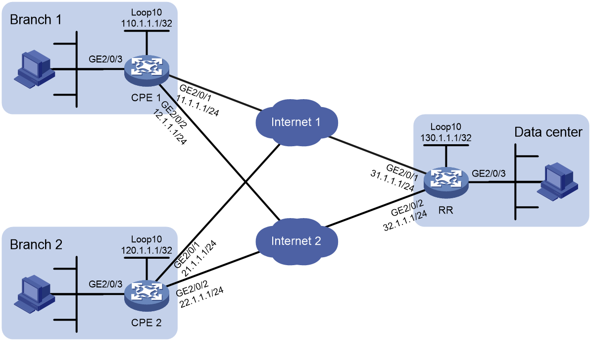
As shown in Figure 7:
· In the SDWAN network, CPE 1 and CPE 2 are deployed in the branches, and RR is deployed in the data center.
· Specify Site 1, Site 2, and Site 3 for CPE 1, CPE 2, and RR, respectively, and configure the device IDs as 1.
· Configure iNQA on CPE 1, CPE 2, and RR. Specify CPE 1 and CPE 2 as collectors, and RR as both collector and analyzer.
· Connect GigabitEthernet 2/0/1 and GigabitEthernet 2/0/2 on CPE 1, CPE 2, and RR to networks Internet1 and Internet2, respectively.
· Create SDWAN tunnel interfaces Tunnel 1 and Tunnel 2 on CPE 1, CPE 2, and RR. Specify the source interface and tunnel packet output interface for Tunnel 1 and Tunnel 2 as GigabitEthernet 2/0/1 and GigabitEthernet 2/0/2, respectively.
· Use GigabitEthernet 2/0/3 to connect CPE 1, CPE 2, and RR to their respective local devices.
Configure RIR as follows to select appropriate links for service flows between the CPEs and RR:
· Configure flow template 1 and flow template 2 for RIR to select the most suitable SDWAN tunnels for packets with a DSCP value of 1 and packets with a DSCP value of 2, respectively.
· On CPE 1, CPE 2, and RR, associate the quality policies of flow template 1 and flow template 2 with SLA 1 and SLA 2, respectively, implementing link quality detection and evaluation for service flows based on quality policies.
· CPE 1, CPE 2, and RR use the per-session weight-based link selection mode, which is the default mode. No configuration is required.
· Assign the same preference value to the two links in each flow template on CPE 1 and CPE 2. The links will load share traffic when they both meet the service requirements.
· Assign different preference values to the two links in each flow template on RR. The RR will preferentially select the link with a higher preference to forward traffic.
· Configure all output interfaces for SDWAN tunneled packets to meet the service bandwidth requirements.
Prerequisites
Configure IP addresses and subnet masks for the interfaces as shown in Figure 7. Configure a routing protocol and static routes to make sure the devices each have a route to reach one another. (Details not shown.)
Configure NTP to synchronize the clock between CPE 1, CPE 2, and RR.
Procedure
1. Configure the SSL, BGP, IPsec, and STUN settings required for setting up the SDWAN network. For more information, see SDWAN Configuration Guide. (Details not shown.)
2. Configure global SDWAN parameters:
¡ Configure RR:
# Configure site ID 3, site name Site3, device ID 1, site role RR, and the system IP address (primary IP address of interface Loopback 10).
<RR> system-view
[RR] sdwan site-id 3
[RR] sdwan site-name Site3
[RR] sdwan device-id 1
[RR] sdwan site-role rr
[RR] sdwan system-ip loopback 10
# Configure the source UDP port number for SDWAN packets as 3000.
[RR] sdwan encapsulation global-udp-port 3000
¡ Configure CPE 1:
# Configure site ID 1, site name Site1, device ID 1, site role CPE, and the system IP address (primary IP address of interface Loopback 10).
<CPE1> system-view
[CPE1] sdwan site-id 1
[CPE1] sdwan site-name Site1
[CPE1] sdwan device-id 1
[CPE1] sdwan site-role cpe
[CPE1] sdwan system-ip loopback 10
# Configure the source UDP port number for SDWAN packets as 3000.
[CPE1] sdwan encapsulation global-udp-port 3000
¡ Configure CPE 2:
# Configure site ID 2, site name Site2, device ID 1, site role CPE, and the system IP address (primary IP address of interface Loopback 10).
<CPE2> system-view
[CPE2] sdwan site-id 2
[CPE2] sdwan site-name Site2
[CPE2] sdwan device-id 1
[CPE2] sdwan site-role cpe
[CPE2] sdwan system-ip loopback 10
# Configure the source UDP port number for SDWAN packets as 3000.
[CPE2] sdwan encapsulation global-udp-port 3000
3. Configure SDWAN server and clients:
¡ Configure RR as the SDWAN server.
# Configure the TCP port number for the SDWAN server as 4000, specify SSL server policy plc1 for establishing SSL connections to SDWAN clients (CPEs), and enable the SDWAN server on RR.
[RR] sdwan server port 4000
[RR] sdwan ssl-server-policy plc1
[RR] sdwan server enable
¡ Configure CPE 1 as an SDWAN client.
# Specify the system IP address and IP address of the SDWAN server as 130.1.1.1 and 31.1.1.1, respectively, the TCP port number for the SDWAN server as 4000, and SSL client policy plc1 for establishing SSL connections to the SDWAN server (RR).
[CPE1] sdwan server system-ip 130.1.1.1 ip 31.1.1.1 port 4000
[CPE1] sdwan ssl-client-policy plc1
¡ Configure CPE 2 as an SDWAN client.
# Specify the system IP address and IP address of the SDWAN server as 130.1.1.1 and 32.1.1.1, respectively, the TCP port number for the SDWAN server as 4000, and SSL client policy plc1 for establishing SSL connections to the SDWAN server (RR).
[CPE2] sdwan server system-ip 130.1.1.1 ip 32.1.1.1 port 4000
[CPE2] sdwan ssl-client-policy plc1
4. Configure SDWAN tunnel interface parameters:
¡ Configure RR:
# Create SDWAN tunnel interface Tunnel 1, and specify the source interface and tunneled packet output interface for Tunnel 1 as GigabitEthernet 2/0/1.
[RR] interface tunnel1 mode sdwan udp
[RR-Tunnel1] source gigabitethernet 2/0/1
[RR-Tunnel1] tunnel out-interface gigabitethernet 2/0/1
[RR-Tunnel1] ip address unnumbered interface gigabitethernet 2/0/1
# Configure routing domain name rd1, routing domain ID 10, transport network name internet1, transport network ID 10, and interface ID 30 for SDWAN tunnel interface Tunnel 1.
[RR-Tunnel1] sdwan routing-domain rd1 id 10
[RR-Tunnel1] sdwan transport-network internet1 id 10
[RR-Tunnel1] sdwan interface-id 30
[RR-Tunnel1] quit
# Create SDWAN tunnel interface Tunnel 2, and specify the source interface and tunneled packet output interface for Tunnel 2 as GigabitEthernet 2/0/2.
[RR] interface tunnel2 mode sdwan udp
[RR-Tunnel2] source gigabitethernet 2/0/2
[RR-Tunnel2] tunnel out-interface gigabitethernet 2/0/2
[RR-Tunnel2] ip address unnumbered interface gigabitethernet 2/0/2
# Configure routing domain name rd2, routing domain ID 20, transport network name internet2, transport network ID 20, and interface ID 40 for SDWAN tunnel interface Tunnel 2.
[RR-Tunnel2] sdwan routing-domain rd2 id 20
[RR-Tunnel2] sdwan transport-network internet2 id 20
[RR-Tunnel2] sdwan interface-id 40
[RR-Tunnel2] quit
¡ Configure CPE 1:
# Create SDWAN tunnel interface Tunnel 1, and specify the source interface and tunneled packet output interface for Tunnel 1 as GigabitEthernet 2/0/1.
[CPE1] interface tunnel1 mode sdwan udp
[CPE1-Tunnel1] source gigabitethernet 2/0/1
[CPE1-Tunnel1] tunnel out-interface gigabitethernet 2/0/1
# Configure routing domain name rd1, routing domain ID 10, transport network name internet1, transport network ID 10, and interface ID 30 for SDWAN tunnel interface Tunnel 1.
[CPE1-Tunnel1] sdwan routing-domain rd1 id 10
[CPE1-Tunnel1] sdwan transport-network internet1 id 10
[CPE1-Tunnel1] sdwan interface-id 30
[CPE1-Tunnel1] quit
# Create SDWAN tunnel interface Tunnel 2, and specify the source interface and tunneled packet output interface for Tunnel 2 as GigabitEthernet 2/0/2.
[CPE1] interface tunnel2 mode sdwan udp
[CPE1-Tunnel2] source gigabitethernet 2/0/2
[CPE1-Tunnel2] tunnel out-interface gigabitethernet 2/0/2
# Configure routing domain name rd2, routing domain ID 20, transport network name internet2, transport network ID 20, and interface ID 40 for SDWAN tunnel interface Tunnel 2.
[CPE1-Tunnel2] sdwan routing-domain rd2 id 20
[CPE1-Tunnel2] sdwan transport-network internet2 id 20
[CPE1-Tunnel2] sdwan interface-id 40
[CPE1-Tunnel2] quit
¡ Configure CPE 2:
# Create SDWAN tunnel interface Tunnel 1, and specify the source interface and tunneled packet output interface for Tunnel 1 as GigabitEthernet 2/0/1.
[CPE2] interface tunnel1 mode sdwan udp
[CPE2-Tunnel1] source gigabitethernet 2/0/1
[CPE2-Tunnel1] tunnel out-interface gigabitethernet 2/0/1
# Configure routing domain name rd1, routing domain ID 10, transport network name internet1, transport network ID 10, and interface ID 30 for SDWAN tunnel interface Tunnel 1.
[CPE2-Tunnel1] sdwan routing-domain rd1 id 10
[CPE2-Tunnel1] sdwan transport-network internet1 id 10
[CPE2-Tunnel1] sdwan interface-id 30
[CPE2-Tunnel1] quit
# Create SDWAN tunnel interface Tunnel 2, and specify the source interface and tunneled packet output interface for Tunnel 2 as GigabitEthernet 2/0/2.
[CPE2] interface tunnel2 mode sdwan udp
[CPE2-Tunnel2] source gigabitethernet 2/0/2
[CPE2-Tunnel2] tunnel out-interface gigabitethernet 2/0/2
# Configure routing domain name rd2, routing domain ID 20, transport network name internet2, transport network ID 20, and interface ID 40 for SDWAN tunnel interface Tunnel 2.
[CPE2-Tunnel2] sdwan routing-domain rd2 id 20
[CPE2-Tunnel2] sdwan transport-network internet2 id 20
[CPE2-Tunnel2] sdwan interface-id 40
[CPE2-Tunnel2] quit
5. Configure RIR-SDWAN settings:
¡ Configure RR:
# Enable the iNQA analyzer functionality and specify the analyzer ID as 130.1.1.1.
[RR] inqa analyzer
[RR-inqa-analyzer] analyzer id 130.1.1.1
[RR-inqa-analyzer] quit
# Enable the iNQA collector functionality and bind analyzer 130.1.1.1 to the collector.
[RR] inqa collector
[RR-inqa-collector] analyzer 130.1.1.1
[RR-inqa-collector] quit
# Enable the RIR-SDWAN service.
[RR] rir sdwan
# Set the link selection delay to 30 seconds and set the link selection suppression period to 60 seconds.
[RR-rir-sdwan] link-select delay 30
[RR-rir-sdwan] link-select suppress-period 60
# Configure the link quality probe interval.
[RR-rir-sdwan] link-quality probe interval 30
# Create SLA 1 and SLA 2, and configure different link quality thresholds for the SLAs.
[RR-rir-sdwan] sla 1
[RR-rir-sdwan-sla-1] jitter threshold 20
[RR-rir-sdwan-sla-1] delay threshold 60
[RR-rir-sdwan-sla-1] packet-loss threshold 150
[RR-rir-sdwan-sla-1] quit
[RR-rir-sdwan] sla 2
[RR-rir-sdwan-sla-2] jitter threshold 40
[RR-rir-sdwan-sla-2] delay threshold 120
[RR-rir-sdwan-sla-2] packet-loss threshold 300
[RR-rir-sdwan-sla-2] quit
# Create flow template 1 and flow template 2. In each flow template, configure the link preference, per-session expected bandwidth, and quality policy settings. Configure the weight values for the delay, jitter, and packet loss metrics used for computing CQI values as 2, 5, and 7, respectively.
[RR-rir-sdwan] flow 1
[RR-rir-sdwan-flow-1] path sdwan transport-network internet1 preference 10
[RR-rir-sdwan-flow-1] path sdwan transport-network internet2 preference 20
[RR-rir-sdwan-flow-1] expect-bandwidth 300
[RR-rir-sdwan-flow-1] quality-policy sla 1
[RR-rir-sdwan-flow-1] cqi-weight delay 2 jitter 5 packet-loss 7
[RR-rir-sdwan-flow-1] quit
[RR-rir-sdwan] flow 2
[RR-rir-sdwan-flow-2] path sdwan transport-network internet1 preference 20
[RR-rir-sdwan-flow-2] path sdwan transport-network internet2 preference 10
[RR-rir-sdwan-flow-2] expect-bandwidth 300
[RR-rir-sdwan-flow-2] quality-policy sla 2
[RR-rir-sdwan-flow-2] cqi-weight delay 2 jitter 5 packet-loss 7
[RR-rir-sdwan-flow-2] quit
[RR-rir-sdwan] quit
# Configure a QoS policy to match packets with a DSCP value of 1 to flow template 1 and match packets with a DSCP value of 2 to flow template 2. Apply the QoS policy to the inbound direction of GigabitEthernet 2/0/3.
[RR] traffic classifier class1
[RR-classifier-class1] if-match dscp 1
[RR-classifier-class1] quit
[RR] traffic classifier class2
[RR-classifier-class2] if-match dscp 2
[RR-classifier-class2] quit
[RR] traffic behavior behav1
[RR-behavior-behav1] remark flow-id 1
[RR-behavior-behav1] quit
[RR] traffic behavior behav2
[RR-behavior-behav2] remark flow-id 2
[RR-behavior-behav2] quit
[RR] qos policy policy1
[RR-qospolicy-policy1] classifier class1 behavior behav1
[RR-qospolicy-policy1] classifier class2 behavior behav2
[RR-qospolicy-policy1] quit
[RR] interface gigabitethernet 2/0/3
[RR-GigabitEthernet2/0/3] qos apply policy policy1 inbound
[RR-GigabitEthernet2/0/3] quit
¡ Configure CPE 1:
# Enable the iNQA collector functionality and bind analyzer 130.1.1.1 to the collector.
[CPE1] inqa collector
[CPE1-inqa-collector] analyzer 130.1.1.1
[CPE1-inqa-collector] quit
# Enable the RIR-SDWAN service.
[CPE1] rir sdwan
# Set the link selection delay to 30 seconds and set the link selection suppression period to 60 seconds.
[CPE1-rir-sdwan] link-select delay 30
[CPE1-rir-sdwan] link-select suppress-period 60
# Configure the link connectivity probe parameters.
[CPE1-rir-sdwan] probe connect interval 500 timeout 800
# Configure the link quality probe interval.
[CPE1-rir-sdwan] link-quality probe interval 30
# Create SLA 1 and SLA 2, and configure different link quality thresholds for the SLAs.
[CPE1-rir-sdwan] sla 1
[CPE1-rir-sdwan-sla-1] jitter threshold 20
[CPE1-rir-sdwan-sla-1] delay threshold 60
[CPE1-rir-sdwan-sla-1] packet-loss threshold 150
[CPE1-rir-sdwan-sla-1] quit
[CPE1-rir-sdwan] sla 2
[CPE1-rir-sdwan-sla-2] jitter threshold 40
[CPE1-rir-sdwan-sla-2] delay threshold 120
[CPE1-rir-sdwan-sla-2] packet-loss threshold 300
[CPE1-rir-sdwan-sla-2] quit
# Create flow template 1 and flow template 2. In each flow template, configure the link preference, per-session expected bandwidth, and quality policy settings. Configure the weight values for the delay, jitter, and packet loss metrics used for computing CQI values as 2, 5, and 7, respectively.
[CPE1-rir-sdwan] flow 1
[CPE1-rir-sdwan-flow-1] path sdwan transport-network internet1 preference 10
[CPE1-rir-sdwan-flow-1] path sdwan transport-network internet2 preference 10
[CPE1-rir-sdwan-flow-1] expect-bandwidth 300
[CPE1-rir-sdwan-flow-1] quality-policy sla 1
[CPE1-rir-sdwan-flow-1] cqi-weight delay 2 jitter 5 packet-loss 7
[CPE1-rir-sdwan-flow-1] quit
[CPE1-rir-sdwan] flow 2
[CPE1-rir-sdwan-flow-2] path sdwan transport-network internet1 preference 20
[CPE1-rir-sdwan-flow-2] path sdwan transport-network internet2 preference 20
[CPE1-rir-sdwan-flow-2] expect-bandwidth 300
[CPE1-rir-sdwan-flow-2] quality-policy sla 2
[CPE1-rir-sdwan-flow-2] cqi-weight delay 2 jitter 5 packet-loss 7
[CPE1-rir-sdwan-flow-2] quit
[CPE1-rir-sdwan] quit
# Configure a QoS policy to match packets with a DSCP value of 1 to flow template 1 and match packets with a DSCP value of 2 to flow template 2. Apply the QoS policy to the inbound direction of GigabitEthernet 2/0/3.
[CPE1] traffic classifier class1
[CPE1-classifier-class1] if-match dscp 1
[CPE1-classifier-class1] quit
[CPE1] traffic classifier class2
[CPE1-classifier-class2] if-match dscp 2
[CPE1-classifier-class2] quit
[CPE1] traffic behavior behav1
[CPE1-behavior-behav1] remark flow-id 1
[CPE1-behavior-behav1] quit
[CPE1] traffic behavior behav2
[CPE1-behavior-behav2] remark flow-id 2
[CPE1-behavior-behav2] quit
[CPE1] qos policy policy1
[CPE1-qospolicy-policy1] classifier class1 behavior behav1
[CPE1-qospolicy-policy1] classifier class2 behavior behav2
[CPE1-qospolicy-policy1] quit
[CPE1] interface gigabitethernet 2/0/3
[CPE1-GigabitEthernet2/0/3] qos apply policy policy1 inbound
[CPE1-GigabitEthernet2/0/3] quit
¡ Configure CPE 2:
# Enable the iNQA collector functionality and bind analyzer 130.1.1.1 to the collector.
[CPE2] inqa collector
[CPE2-inqa-collector] analyzer 130.1.1.1
[CPE2-inqa-collector] quit
# Enable the RIR-SDWAN service.
[CPE2] rir sdwan
# Set the link selection delay to 30 seconds and set the link selection suppression period to 60 seconds.
[CPE2-rir-sdwan] link-select delay 30
[CPE2-rir-sdwan] link-select suppress-period 60
# Configure the link quality probe interval.
[CPE2-rir-sdwan] link-quality probe interval 30
# Create SLA 1 and SLA 2, and configure different link quality thresholds for the SLAs.
[CPE2-rir-sdwan] sla 1
[CPE2-rir-sdwan-sla-1] jitter threshold 20
[CPE2-rir-sdwan-sla-1] delay threshold 60
[CPE2-rir-sdwan-sla-1] packet-loss threshold 150
[CPE2-rir-sdwan-sla-1] quit
[CPE2-rir-sdwan] sla 2
[CPE2-rir-sdwan-sla-2] jitter threshold 40
[CPE2-rir-sdwan-sla-2] delay threshold 120
[CPE2-rir-sdwan-sla-2] packet-loss threshold 300
[CPE2-rir-sdwan-sla-2] quit
# Create flow template 1 and flow template 2. In each flow template, configure the link preference, per-session expected bandwidth, and quality policy settings. Configure the weight values for the delay, jitter, and packet loss metrics used for computing CQI values as 2, 5, and 7, respectively.
[CPE2-rir-sdwan] flow 1
[CPE2-rir-sdwan-flow-1] path sdwan transport-network internet1 preference 10
[CPE2-rir-sdwan-flow-1] path sdwan transport-network internet2 preference 10
[CPE2-rir-sdwan-flow-1] expect-bandwidth 300
[CPE2-rir-sdwan-flow-1] quality-policy sla 1
[CPE2-rir-sdwan-flow-1] cqi-weight delay 2 jitter 5 packet-loss 7
[CPE2-rir-sdwan-flow-1] quit
[CPE2-rir-sdwan] flow 2
[CPE2-rir-sdwan-flow-2] path sdwan transport-network internet1 preference 20
[CPE2-rir-sdwan-flow-2] path sdwan transport-network internet2 preference 20
[CPE2-rir-sdwan-flow-2] expect-bandwidth 300
[CPE2-rir-sdwan-flow-2] quality-policy sla 2
[CPE2-rir-sdwan-flow-2] cqi-weight delay 2 jitter 5 packet-loss 7
[CPE2-rir-sdwan-flow-2] quit
[CPE2-rir-sdwan] quit
# Configure a QoS policy to match packets with a DSCP value of 1 to flow template 1 and match packets with a DSCP value of 2 to flow template 2. Apply the QoS policy to the inbound direction of GigabitEthernet 2/0/3.
[CPE2] traffic classifier class1
[CPE2-classifier-class1] if-match dscp 1
[CPE2-classifier-class1] quit
[CPE2] traffic classifier class2
[CPE2-classifier-class2] if-match dscp 2
[CPE2-classifier-class2] quit
[CPE2] traffic behavior behav1
[CPE2-behavior-behav1] remark flow-id 1
[CPE2-behavior-behav1] quit
[CPE2] traffic behavior behav2
[CPE2-behavior-behav2] remark flow-id 2
[CPE2-behavior-behav2] quit
[CPE2] qos policy policy1
[CPE2-qospolicy-policy1] classifier class1 behavior behav1
[CPE2-qospolicy-policy1] classifier class2 behavior behav2
[CPE2-qospolicy-policy1] quit
[CPE2] interface gigabitethernet 2/0/3
[CPE2-GigabitEthernet2/0/3] qos apply policy policy1 inbound
[CPE2-GigabitEthernet2/0/3] quit
6. Configure flow ID-based traffic rate statistics for tunnels:
# On RR, enable flow ID-based traffic rate statistics for tunnels and set the statistics collection interval to 5 seconds.
[RR] tunnel flow-statistics enable
[RR] tunnel flow-statistics interval 5
# On CPE 1, enable flow ID-based traffic rate statistics for tunnels and set the statistics collection interval to 5 seconds.
[CPE1] tunnel flow-statistics enable
[CPE1] tunnel flow-statistics interval 5
# On CPE 2, enable flow ID-based traffic rate statistics for tunnels and set the statistics collection interval to 5 seconds.
[CPE2] tunnel flow-statistics enable
[CPE2] tunnel flow-statistics interval 5
Verifying the configuration
1. Display link selection information on CPE 1:
# Initiate only UDP services from Branch 1 to the data center. The services have multiple sessions and the DSCP of the service traffic is 1. (Details not shown.)
# Display flow ID-based traffic rate statistics for tunnels to verify that both Tunnel 1 and Tunnel 2 in flow template 1 have service traffic.
[CPE1] display tunnel flow-statistics
Flow 1:
Interface Out pps Out bps VPN instance
Tunnel1 300 300000 vpna
Tunnel2 300 300000 vpna
The output shows that RIR-SDWAN selects two links to load share the service traffic with a DSCP value of 1 in flow template 1.
# Initiate only UDP services from Branch 1 to the data center. The services have multiple sessions and the DSCP of the service traffic is 2. (Details not shown.)
# Display flow ID-based traffic rate statistics for tunnels to verify that both Tunnel 1 and Tunnel 2 in flow template 2 have service traffic.
[CPE1] display tunnel flow-statistics
Flow 2:
Interface Out pps Out bps VPN instance
Tunnel1 300 300000 vpna
Tunnel2 300 300000 vpna
The output shows that RIR-SDWAN selects two links to load share the service traffic with a DSCP value of 2 in flow template 2.
2. Display link selection information on CPE 2:
The procedure is the same as that on CPE 1. (Details not shown.)
3. Display link selection information on RR:
# Initiate only UDP services from the data center to Branch 1. The services have multiple sessions and the DSCP of the service traffic is 1. (Details not shown.)
# Display flow ID-based traffic rate statistics for tunnels to verify that only Tunnel 1 in flow template 1 has service traffic.
[RR] display tunnel flow-statistics
Flow 1:
Interface Out pps Out bps VPN instance
Tunnel1 300 300000 vpna
The output shows that RIR-SDWAN preferentially selects Tunnel 1 for the service traffic with a DSCP value of 1 in flow template 1.
# Initiate only UDP services from the data center to Branch 1. The services have multiple sessions and the DSCP of the service traffic is 2. (Details not shown.)
# Display flow ID-based traffic rate statistics for tunnels to verify that only Tunnel 2 in flow template 2 has service traffic.
[RR] display tunnel flow-statistics
Flow 2:
Interface Out pps Out bps VPN instance
Tunnel2 300 300000 vpna
The output shows that RIR-SDWAN preferentially selects Tunnel 2 for the service traffic with a DSCP value of 2 in flow template 2.