- Table of Contents
-
- 09-Radio Resources Management Configuration Guide
- 00-Preface
- 01-Radio management configuration
- 02-WLAN radio load balancing configuration
- 03-WLAN load balancing configuration
- 04-WLAN radio resource measurement configuration
- 05-Band navigation configuration
- 06-WLAN RRM configuration
- 07-Channel scanning configuration
- 08-Spectrum management configuration
- Related Documents
-
| Title | Size | Download |
|---|---|---|
| 06-WLAN RRM configuration | 593.28 KB |
Contents
High-density deployment optimization
Restrictions and guidelines: WLAN RRM configuration
Configuring scheduled auto-DFS
Setting the DFS sensitivity mode
Configuring DFS trigger parameters
Configuring an RRM holddown group
Configuring orthogonal channel optimization for 2.4 GHz radios
Setting the power calibration interval for auto-TPC
Configuring TPC trigger parameters
Setting the minimum transmit power
Setting the maximum transmit power
Configuring an RRM holddown group
Configuring blind spot detection
Configuring automatic bandwidth adjustment
Enabling automatic bandwidth adjustment
Setting the interval for automatic bandwidth adjustment
Enabling SNMP notifications for WLAN RRM
Setting the trap thresholds for adjacent-channel and co-channel interference
Filtering out APs that can be shut down in high-density scenarios
Verifying and maintaining WLAN RRM
WLAN RRM configuration examples
Example: Configuring periodic auto-DFS
Example: Configuring scheduled auto-DFS
Example: Configuring automatic bandwidth adjustment
Configuring WLAN RRM
About WLAN RRM
WLAN Radio Resource Management (RRM) provides an intelligent and scalable radio management solution to allow a WLAN to adapt to environment changes and maintain the optimal radio resource condition.
Background
With the development of wireless networks and the massive growth of wireless users, wireless network management is becoming increasingly challenging. The ever-growing user demands for network applications and the constant network changes make it an urgent issue to provide high-quality network services for users. Traditional O&M methods require network administrators to manually configure radio parameters (channel, power, and bandwidth), presenting the following challenges:
· It is difficult for users lacking wireless network knowledge to configure radio parameters.
· Manual configuration of radio parameters in large-scale networks is complex and time-consuming.
· The configuration cannot change with network environments, making it difficult to provide the optimal network performance.
· The maintenance costs are high, with significant personnel and time investments.
· It is difficult to discover network issues, affecting user experience.
RRM technology is developed to resolve these issues. RRM can monitor the network state in real time and automatically adjust the radio channel, power, and bandwidth to optimize the network performance.
Key technologies
WLAN RRM uses the following techniques for radio management:
· Channel adjustment
In a WLAN, a radio can only work on a limited number of channels, where there might be severe interference from both wireless devices and non-wireless devices, such as radar transmitters and microwave ovens. With channel adjustment, the system automatically assigns an optimal channel for each radio in real time to avoid co-channel interference and interference from other radio sources.
· Power adjustment
Traditional power control sets the transmit power of a radio to the maximum value to maximize the signal coverage, which causes unnecessary interference to other wireless devices and sticky clients. This reduces the overall capacity and user experience of the system, and cannot meet the high throughput requirement.
Power adjustment in RRM can ensure the signal coverage and reduce unnecessary interference at the same time by allocating a reasonable transmit power for each radio.
· Bandwidth adjustment
Configuring all radios to use the maximum bandwidth increases the negotiated rate between AP and client, but causes severe co-channel interference because of limited wireless channels.
Bandwidth adjustment in RRM can balance negotiated rate and interference and improve the capacity of the entire network.
Operating mechanism
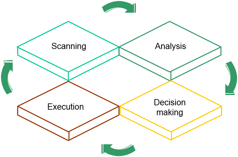
RRM operates as follows:
1. Scanning
APs scan channels regularly after coming online and report collected information to the AC at specific intervals. To avoid affecting wireless services, APs scan channels only when no service traffic is being transmitted.
2. Analyzing
The AC analyzes the received information, including channel quality, channel interference conditions, and adjacent AP distribution, and builds a model of the surrounding network with real-time awareness of network changes for decision making.
3. Decision making
Based on the analysis result, the AC uses intelligent algorithms to adjust and optimize radio resources, and automatically evaluates the impact of the adjustment on the network to ensure that the system is reliably adjusted to accommodate changes in the WLAN.
4. Execution
The AC sends the adjustment policy to the target AP, and the AP adjusts the channel, bandwidth, and transmit power as configured in the policy. You can view the history of AP radio adjustment on the AC.
The AC continuously monitors the network environment and records any wireless environment changes for the next round of adjustment.
Figure 1 RRM working mechanism
Dynamic frequency selection
About dynamic frequency selection
Radio frequency interference affects wireless user experience. Common types of interference includes the following:
· Co-channel interference—Interference between APs) working on the same channel. The 2.4 GHz band has very limited non-interfering channels. In actual scenarios, a channel is often used by multiple APs, leading to co-channel interference issues.
· Adjacent-channel interference—Interference between APs working on different channels. If APs with different center frequencies have overlapping transmission bandwidth, adjacent-channel interference occurs. This issue usually occurs in scenarios where wireless APs from multiple manufacturers are deployed together. When the 2.4 GHz radios of the APs from different manufacturers use different orthogonal channel combinations, adjacent-channel interference occurs if they are close in distance or transmit at high power. For example, if H3C APs use orthogonal channel combination 1, 6, 11, and APs from other manufacturers use orthogonal channel combination 3, 8, 13, severe spectrum overlapping might occur.
To reduce channel interference, dynamic frequency selection provides the features:
· Channel selection—Selects the optimal channel for each AP. For more information, see "Channel selection."
· Orthogonal channel combination selection—Dynamically tracks the orthogonal channel combinations used by APs from other manufacturers and uses optimization algorithms to reduce adjacent-channel interference. For more information, see "Orthogonal channel combination selection for 2.4 GHz radios."
Channel selection
Two adjacent radios on the same channel might cause signal collision, and other radio sources such as radar signals and microwave ovens might interfere with the operation of radios. With DFS, the AC selects an optimal channel for each radio in real time to avoid co-channel interference and interference from other radio sources.
The following factors will trigger DFS:
· Error code rate—Physical layer error code rate and CRC error rate. CRC error rate shows the proportion of packets with CRC errors among all 802.11 packets.
· Interference rate—Proportion of interference packets among all data packets. Interference packets are packets destined for other radios.
· Interference condition—DFS is triggered when both the channel usage threshold and interference ratio threshold are reached or exceeded, but the received service traffic fails to reach the service traffic threshold.
¡ Channel usage threshold—Proportion of channel resources used for packet transmitting and receiving.
¡ Interference ratio threshold—Proportion of channel resources used by interferences to the total used channel resources.
¡ Service traffic threshold—Proportion of received service traffic to the total received traffic.
· Retransmission rate—Proportion of retransmitted packets to the total transmitted packets. The retransmission rate threshold is defined by the system and cannot be modified. An AP retransmits a packet if it fails to receive an ACK before the response timeout timer expires.
· Noise threshold—Noise detected by the AC in the current working channel.
The AC uses the following procedure to perform DFS for a radio:
2. Compares the quality between the current channel and the optimal channel. The radio does not use the optimal channel until the quality gap between the two channels exceeds the tolerance level.
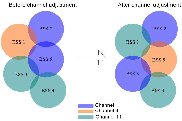
Figure 2 shows a DFS example. When the quality of the channels for BSS 1, BSS 3, and BSS 5 reaches a DFS threshold, the AC selects an optimal channel for each of them. This ensures wireless service quality.
Figure 2 Dynamic frequency selection
Orthogonal channel combination selection for 2.4 GHz radios
In scenarios where APs from multiple vendors are deployed, each vendor's AP might select different orthogonal channel combinations for the 2.4G band. Differences among vendors prevent the unified management and planning of AP configuration, leading to interference between 2.4 GHz working channels, significantly impacting user experience. To address the mentioned issues, H3C APs can trace the working channel conditions of neighbor APs in the 2.4G band in real-time. When adjusting channels automatically, an H3C AP selects a set of orthogonal channels most used by third-party APs, significantly reducing interference between APs from different vendors. A radio identifies other detectable radios as its neighbors. For a radio, its neighbors are classified into the following categories:
· Managed neighbors—The AP of a managed neighbor connects to the same AC as the AP of the current radio.
· Unmanaged neighbors—The AP of an unmanaged neighbor connects to a different AC than the AP of the current radio.
Orthogonal channel combination selection is triggered for a 2.4 GHz radio when the following conditions are met:
· The number of neighbors for the radio reaches or exceeds the specified threshold.
· The ratio between the number of unmanaged neighbors and the number of total neighbors reaches or exceeds the specified threshold.
· The ratio between the number of unmanaged neighbors and the number of total neighbors for an orthogonal channel combination reaches or exceeds the specified threshold.
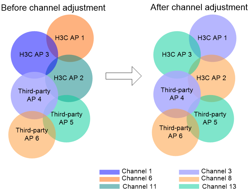
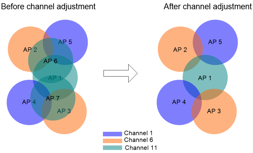
Figure 3 shows an example of orthogonal channel combination selection. In this example, only one radio is enabled on each AP, and a radio is represented by its AP. Before channel optimization, the APs from different manufactures use different orthogonal channel combinations. AP 3 from H3C operates in channel 1, and AP 4 from a third party operates in channel 3. Severe interference exists among these APs. After channel optimization, the H3C APs use a set of orthogonal channels of the third-party APs.
Figure 3 Orthogonal channel combination selection
Transmit power control
About transmit power control
· Signal strength of neighbor APs detected by the AP—Used to identify whether the current transmit power is reasonable.
· Signal strength of the AP detected by clients—Used to identify whether coverage holes exist. In addition, the AC will exclude sticky clients to prevent incorrect transmit power adjustment from making the sticky client issue more serious.
When you use automatic transmit power adjustment, consider the following elements:
· When APs are deployed properly, the AC obtains AP transmit power information from the neighbor report and uses optimization algorithms to adjust the transmit power to an appropriate value. For more information, see "Transmit power adjustment through neighbor reports."
· In high location installation, blocking, and other special scenarios, the AC must adjust the AP transmit power and ensure a good RSSI at the same time. For more information, see "Transmit power adjustment through RSSI packets."
Transmit power adjustment through neighbor reports
TPC enables the AC to dynamically control access point transmit power based on real-time WLAN conditions. It can achieve desired RF coverage while avoiding channel interference between radios.
The AC maintains a neighbor report for each radio on its associated APs to record information about other radios detected by this radio. The AC can manage only radios associated with it.
The AC uses the following procedure to perform TPC for a radio:
1. Determines whether the number of manageable radios (all-channel radios or overlapping-channel radios) that can detect this radio has reached the adjacency factor.
If the number has not reached the adjacency factor, the radio uses the maximum transmit power.
If the number has reached the adjacency factor, the AC goes to step 2:
2. Ranks the radio's RSSIs detected by these manageable radios in descending order.
3. Compares the RSSI specified by the adjacency factor with the power adjustment threshold and takes one of the following actions:
¡ Decreases the radio's transmit power when the RSSI rises above the threshold.
¡ Increases the radio's transmit power when the RSSI drops below the threshold.
Radios that can participate in TPC calculation for a radio include the following types:
· All-channel radios—Include all manageable radios that detect the radio. TPC based on all-channel radios can better control the signal coverage.
· Overlapping-channel radios—Include manageable radios that detect the radio on a channel overlapping with the radio's transmit channel. TPC based on overlapping-channel radios can expand signal coverage without increasing interference.
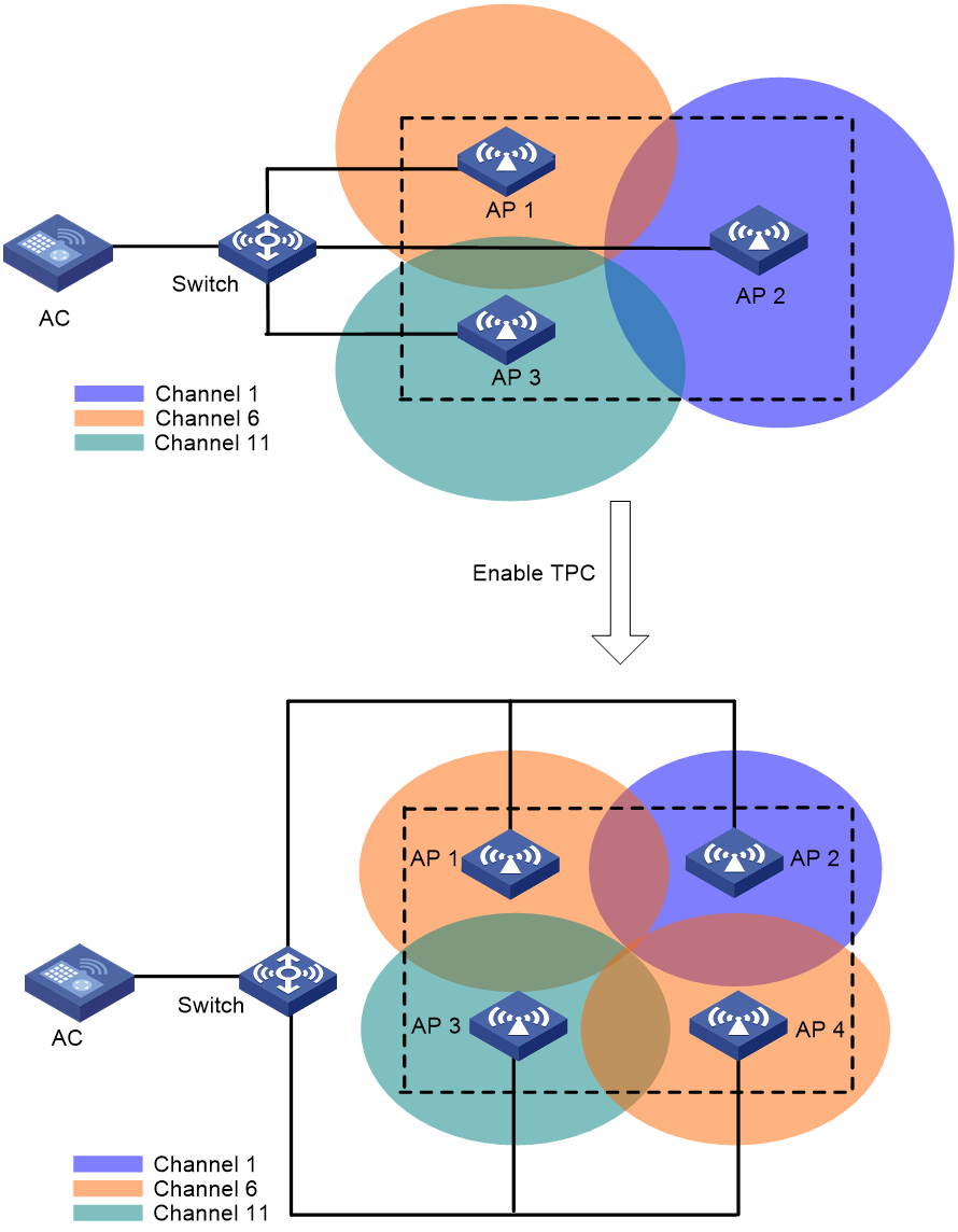
As shown in Figure 4, each AP has only one radio enabled. Before AP 4 joins, the number of manageable radios detected by each radio does not reach the adjacency factor 3. The radios use the maximum transmit power. After AP 4 joins, the number of manageable radios detected by each radio reaches the adjacency factor 3. The AC uses TPC to adjust the transmit powers for all radios.
Figure 4 Transmit power control
Transmit power adjustment through RSSI packets
When APs are not properly deployed, adjusting transmit power through only neighbor reports might not ensure a good RSSI. Typical scenarios are as follows:
· APs are installed at a high location.
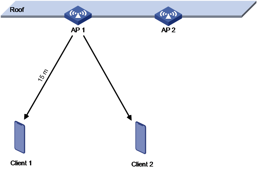
As shown in Figure 5, AP 1 and AP 2 are installed at a high location and strong transmit power can be detected between the APs. In this case, the AC reduces the AP transmit power to reduce radio interference. However, reducing the transmit power decreases the RSSI because the APs are installed far from the clients. This leads to a poor user experience such as weak RSSI and low negotiation rate.
Figure 5 AP high location installation scenario
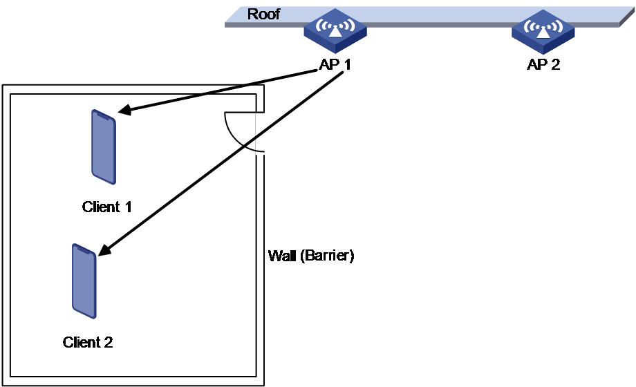
· Obstacles exist between APs and clients.
As shown in Figure 6 and Figure 7, the APs are installed at a high location and a ceiling exists between the APs and the clients. Strong transmit power can be detected between the APs, so the AC reduces the AP transmit power to reduce radio interference. However, reducing the transmit power decreases the RSSI because the ceiling causes severe signal attenuation.
Figure 6 Obstacle scenario (1)
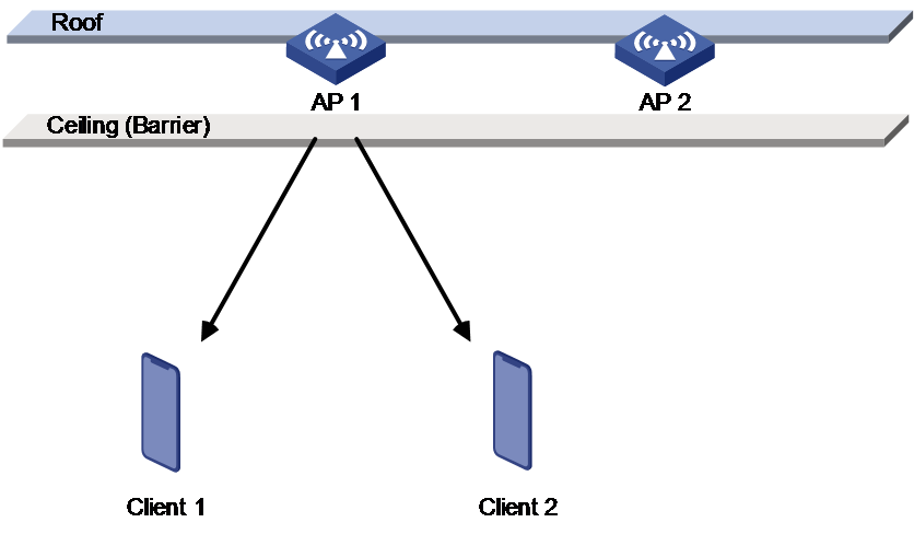
Figure 7 Obstacle scenario (2)
In the above scenarios, the AC supports coverage blind spot detection through the RSSI packets sent from the clients. The AC operates as follows:
1. Identify whether the packets from clients are weak signal packets. If the RSSI is lower than the configured RSSI threshold, the packets are weak signal packets.
2. Identify whether the clients are weak signal clients. A client is a weak signal client when the following conditions are met:
¡ The number of weak signal packets from the client exceeds the configured threshold.
¡ The weak signal packet ratio from the client exceeds the configured threshold.
3. Identify whether radio coverage blind spots exist. Radio coverage blind spots exist when the following conditions are met:
¡ The number of associated weak signal clients on the radio exceeds the configured threshold.
¡ The ratio of associated weak signal clients on the radio exceeds the configured threshold.
If coverage holes are detected, the AC will increase the AP transmit power automatically to ensure user experience.
Bandwidth adjustment
802.11n and 802.11ac allow combination of adjacent channels to increase the data transmisstion rate. However, this practice can decrease data transmission stability, because signal interference is easy to occur.
Automatic bandwidth adjustment enables the AC to start channel quality detection when the automatic bandwidth adjustment interval is reached, and determines whether to perform bandwidth adjustment. It decreases the bandwidth for a radio to reduce interference if the number of neighbor radios for that radio is large, and increase the bandwidth to increase transmission rate if the number is small.
Auto bandwidth adjustment uses the following rules:
· Decreases radio bandwidth to reduce interference when APs are densely deployed.
· Increases radio bandwidth to increase the data transmission speed when APs are sparsely deployed.
· Reduces overlapping channels for adjacent APs as much as possible to minimize co-channel interference.
· Ensures that APs and clients can negotiate appropriate rates, ensuring the access rate of clients and increasing the capacity of the entire network.
The AC evaluates the channel quality when each auto bandwidth adjustment period is reached and determines whether to adjust the bandwidth based on the evaluation result.
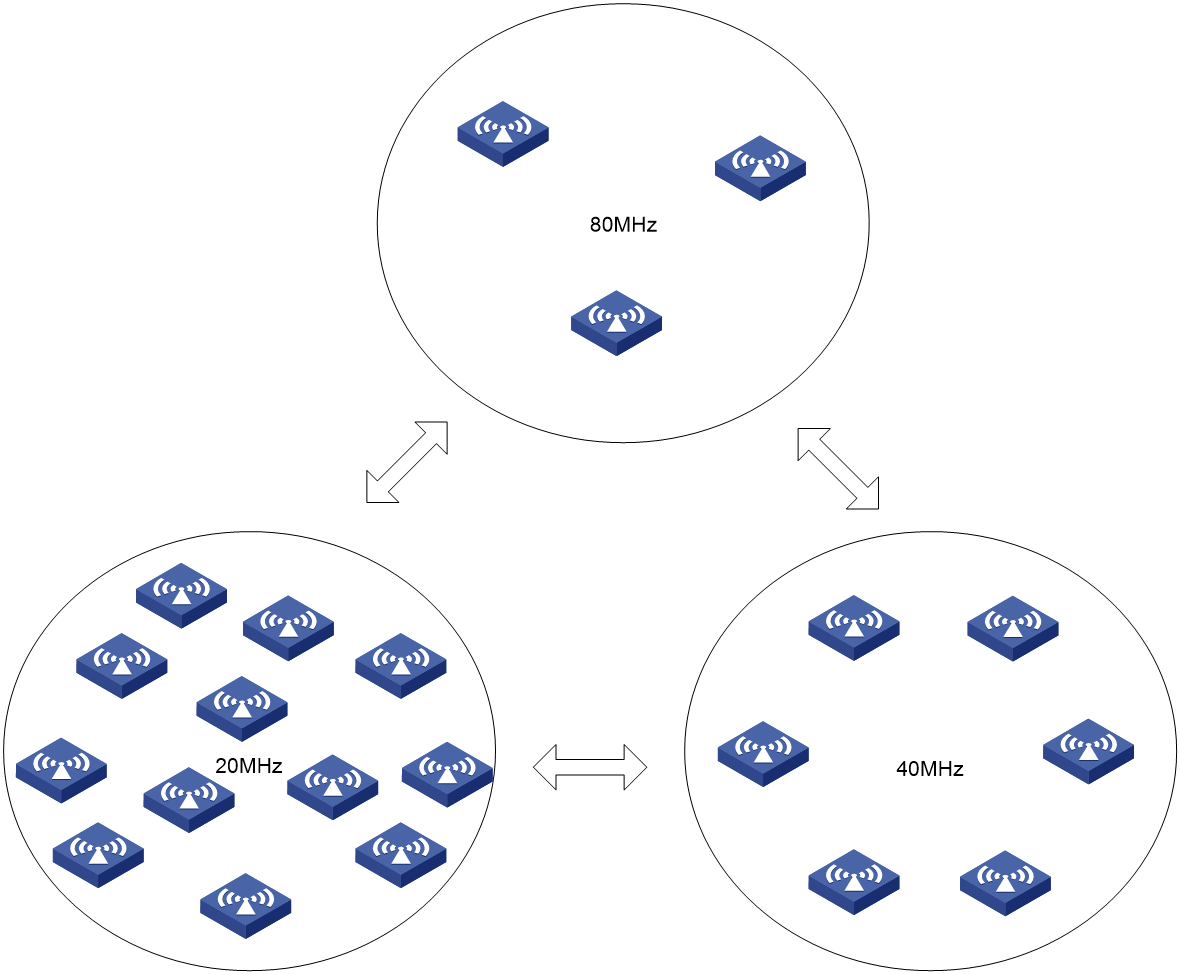
As shown in Figure 8, when the AC detects that too many neighbor APs and clients exist for an AP, it decreases the radio bandwidth to reduce interference. When the AC detects that only a few neighbor APs and clients exist for an AP, it increases the radio bandwidth to increase the transmission speed and network capacity.
Figure 8 Automatic bandwidth adjustment
High-density deployment optimization
Public places such as stadiums and large conference centers usually have high density and high concurrency requirements on wireless services. As a result, a large number of APs are usually deployed in such places. Spectrum resources are limited, so interference among APs is particularly severe when the APs are deployed densely. To resolve this issue, configure high-density deployment optimization to automatically calculate and identify redundant APs. You can view the redundant APs and disable their radios to reduce interference.
As shown in Figure 9, only one radio is enabled on each AP, and a radio is represented by its AP. Before channel optimization, APs 1, 6, and 7 all operate in channel 11, resulting in severe interference. After channel optimization, APs 6 and 7 are disabled to reduce interference while ensuring wireless service coverage.
Figure 9 High-density deployment optimization
Restrictions and guidelines: WLAN RRM configuration
You can configure APs by using the following methods:
· Configure APs one by one in AP view.
· Assign APs to an AP group and configure the AP group in AP group view.
· Configure all APs in global configuration view.
For an AP, the settings made in these views for the same parameter take effect in descending order of AP view, AP group view, and global configuration view.
WLAN RRM tasks at a glance
To configure RRM, perform the following tasks:
· Configuring automatic bandwidth adjustment
· Configuring a radio baseline
· Enabling SNMP notifications for WLAN RRM
· Setting the trap thresholds for adjacent-channel and co-channel interference
· Filtering out APs that can be shut down in high-density scenarios
Configuring DFS
About DFS
The AC supports the following DFS methods:
· Periodic auto-DFS—The AC automatically performs DFS for a radio at the channel calibration interval.
· Scheduled auto-DFS—The AC performs DFS at the specified time in a time range. Use this method when interference is severe to avoid affecting ongoing wireless services.
· On-demand DFS—The AC waits for a channel calibration interval and then performs DFS for all radios. You must perform this task every time you want the AC to perform DFS for radios.
Tasks at a glance
To configure DFS, perform the following tasks:
2. Choose the following tasks as needed:
¡ Configuring periodic auto-DFS
¡ Configuring scheduled auto-DFS
You cannot configure periodic auto-DFS and scheduled auto-DFS at the same time.
3. (Optional.) Setting the DFS sensitivity mode
4. (Optional.) Configuring DFS trigger parameters
You can configure DFS trigger parameters only when the DFS sensitivity mode is custom.
5. (Optional.) Configuring an RRM holddown group
6. (Optional.) Enabling WSA collaboration
7. (Optional.) Configuring orthogonal channel optimization for 2.4 GHz radios
Configuration prerequisites
For DFS to work, configure the AC to automatically select a channel for a radio and not lock the channel by using the channel auto unlock command. For more information about the channel { channel-number | auto { lock | unlock } } command, see radio management in Radio Resources Management Command Reference.
Enabling auto-DFS
Restrictions and guidelines
To use periodic or scheduled auto-DFS, you must enable the auto-DFS feature.
You can enable auto-DFS in RRM view, an AP group's RRM view, or global configuration view. The priorities for configurations in RRM view, an AP group's RRM view, or global configuration view are in descending order.
Enabling auto-DFS globally
1. Enter system view.
system-view
2. Enter global configuration view.
wlan global-configuration
3. Enable auto-DFS.
calibrate-channel self-decisive enable { 2.4g | 5g | 6g | all }
By default, auto-DFS is enabled.
You can enable auto-DFS for the 2.4 GHz band, 5 GHz band, 6 GHz band, or all bands.
Enabling auto-DFS in RRM view or an AP group's RRM view
1. Enter system view.
system-view
2. Enter AP view or an AP group's AP model view.
¡ Enter AP view.
wlan ap ap-name
¡ Execute the following commands in sequence to enter an AP group's AP model view:
wlan ap-group group-name
ap-model ap-model
3. Enter radio view.
radio radio-id
4. Enter RRM view.
rrm
5. Enable auto-DFS.
calibrate-channel self-decisive enable
By default:
¡ In radio view, the configuration in an AP group's RRM view is used. If auto-DFS is not configured in AP group view, the AP uses the configuration in global configuration view.
¡ In an AP group's radio view, the configuration in global configuration view is used.
Configuring periodic auto-DFS
Restrictions and guidelines
For wireless service stability, you can configure DFS suppression to suppress periodic auto-DFS when the online client quantity reaches the specified threshold.
Procedure
1. Enter system view.
system-view
2. (Optional.) Set the channel calibration interval.
wlan rrm calibration-channel interval minutes
By default, the channel calibration interval is 23 minutes.
3. Enter AP view or an AP group's AP model view.
¡ Enter AP view.
wlan ap ap-name
¡ Execute the following commands in sequence to enter an AP group's AP model view:
wlan ap-group group-name
ap-model ap-model
4. Enter radio view.
radio radio-id
5. Enter RRM view.
rrm
6. Set the auto-DFS mode to periodic.
calibrate-channel mode periodic
By default:
¡ In RRM view, the configuration in an AP group's RRM view is used.
¡ In an AP group's RRM view, the auto-DFS mode is periodic.
7. (Optional.) Configure DFS suppression.
calibrate-channel suppression { disable | enable [ client-number number ] }
By default:
¡ In RRM view, the configuration in an AP group's RRM view is used.
¡ In an AP group's RRM view, DFS suppression is disabled.
Configuring scheduled auto-DFS
About this task
Scheduled auto-DFS enables the AC to collect statistics to generate channel reports and neighbor reports within the specified time range and perform DFS based on the reports.
Creating a time range
1. Enter system view.
system-view
2. Create a time range.
time-range time-range-name { start-time to end-time days [ from time1 date1 ] [ to time2 date2 ] | from time1 date1 [ to time2 date2 ] | to time2 date2 }
3. Enter AP view or an AP group's AP model view.
¡ Enter AP view.
wlan ap ap-name
¡ Execute the following commands in sequence to enter an AP group's AP model view:
wlan ap-group group-name
ap-model ap-model
4. Enter radio view.
radio radio-id
5. Enter RRM view.
rrm
6. Specify a time range for channel monitoring.
calibrate-channel monitoring time-range time-range-name
By default:
¡ In RRM view, the configuration in an AP group's RRM view is used.
¡ In an AP group's RRM view, no time range is specified for channel monitoring.
Configuring a job and schedule
1. Enter system view.
system-view
2. Create a job and enter its view.
scheduler job job-name
3. Execute the following commands in sequence to assign commands to the job:
command 1 system-view
command 2 wlan ap ap-name [ model model-name ]
command 3 radio radio-id
command 4 rrm
command 5 calibrate-channel pronto
By default, no command is assigned to a job.
4. Return to system view.
quit
5. Create a schedule and enter its view.
scheduler schedule schedule-name
6. Assign a job to the schedule.
job job-name
By default, no job is assigned to a schedule.
7. Assign a user role to the schedule.
user-role role-name
By default, the user role of the schedule creator is assigned to the schedule.
8. Choose one of the following tasks:
¡ Specify an execution date and time for the schedule.
time at time date
¡ Specify one or more execution days and the execution time for the schedule.
time once at time [ month-date month-day | week-day week-day&<1-7> ]
¡ Specify the delay time for executing the schedule.
time once delay time
By default, no execution time is specified for a schedule.
Enabling auto-DFS
1. Enter system view.
system-view
2. Enter AP view or an AP group's AP model view.
¡ Enter AP view.
wlan ap ap-name
¡ Execute the following commands in sequence to enter an AP group's AP model view:
wlan ap-group group-name
ap-model ap-model
3. Enter radio view.
radio radio-id
4. Enter RRM view.
rrm
5. Set the auto-DFS mode to scheduled.
calibrate-channel mode scheduled
By default:
¡ In RRM view, the configuration in an AP group's RRM view is used.
¡ In an AP group's RRM view, the auto-DFS mode is periodic.
Configuring on-demand DFS
About this task
You can perform on-demand DFS for all APs or for the specified AP.
For an all-AP or AP group-specific DFS, the AC determines whether to perform a DFS based on the condition of the current working channel.
For an AP-specific DFS, you can specify the force keyword for the AC to change the working channel of the AP directly without considering the condition of the current working channel. If you do not specify the keyword, the AC determines whether to perform a DFS based on the condition of the current working channel.
Restrictions and guidelines
|
|
CAUTION: On-demand DFS for all APs consumes a lot of system resources on the AC and might affect service operation. Please use this feature with caution. |
AP-specific DFS does not take effect in an AC hierarchy network or on inside APs.
Performing on-demand DFS for all APs or APs in the specified AP group
1. Enter system view.
system-view
2. Enable on-demand DFS for radios of all APs or APs in the specified AP group.
wlan calibrate-channel pronto ap { all | ap-group group-name } { 2.4g | 5g | 6g | all }
3. (Optional.) Set the channel calibration interval.
wlan rrm calibration-channel interval minutes
By default, the channel calibration interval is 23 minutes.
Performing on-demand DFS for the specified AP
1. Enter system view.
system-view
2. Perform on-demand DFS for the specified AP.
wlan rrm calibration-channel ap name ap-name [ radio radio-id ] [ force ]
The system will take a few minutes to scan channels and collect channel data. This might cause packet loss. During the calibration process, do not disable the radios or change channel scanning or WLAN RRM settings.
Setting the DFS sensitivity mode
About this task
DFS supports the following sensitivity modes: low, medium, high, and custom. DFS configured with a higher sensitivity can be triggered more easily.
Restrictions and guidelines
When the system switches between custom mode and high/mid/low sensitivity mode, auto DFS trigger parameters (including interference ratio threshold, CRC error threshold, and tolerance level) will be restored to default values (which vary by mode) and cannot be manually modified. If needed, record auto DFS trigger parameters in custom mode.
Auto DFS trigger parameters (including interference ratio threshold, CRC error threshold, and tolerance level) can only be manually configured in custom sensitivity mode.
Procedure
1. Enter system view.
system-view
2. Enter AP view or an AP group's AP model view.
¡ Enter AP view.
wlan ap ap-name
¡ Execute the following commands in sequence to enter an AP group's AP model view:
wlan ap-group group-name
ap-model ap-model
3. Enter radio view.
radio radio-id
4. Enter RRM view.
rrm
5. Set the DFS sensitivity mode.
calibrate-channel self-decisive sensitivity { custom | high | low | medium }
By default:
¡ In RRM view, the configuration in an AP group's RRM view is used.
¡ In an AP group's RRM view, the DFS sensitivity mode is custom.
Configuring DFS trigger parameters
Restrictions and guidelines
As a best practice for accurate channel adjustment, configure the same DFS trigger parameters for all radios enabled with DFS.
You can configure DFS trigger parameters only when the DFS sensitivity mode is custom.
Configuring global auto DFS parameters
1. Enter system view.
system-view
2. Enter global configuration view.
wlan global-configuration
3. Set the CRC error threshold for 2.4 GHz, 5 GHz, and 6 GHz radios.
¡ For 2.4 GHz radios:
calibrate-channel 2.4g crc-error-threshold percent
By default, the CRC error threshold is 0 for 2.4 GHz radios.
¡ For 5 GHz radios:
calibrate-channel 5g crc-error-threshold percent
By default, the CRC error threshold is 0 for 5 GHz radios.
¡ For 6 GHz radios:
calibrate-channel 6g crc-error-threshold percent
By default, the CRC error threshold is 0 for 6 GHz radios.
4. Set the channel usage threshold for 2.4 GHz, 5 GHz, and 6 GHz radios.
¡ For 2.4 GHz radios:
calibrate-channel 2.4g channel-usage-threshold percent percent
By default, the channel usage threshold is 60 for 2.4 GHz radios.
¡ For 5 GHz radios:
calibrate-channel 5g channel-usage-threshold percent percent
By default, the channel usage threshold is 60 for 5 GHz radios.
¡ For 6 GHz radios:
calibrate-channel 6g channel-usage-threshold percent percent
By default, the channel usage threshold is 60 for 6 GHz radios.
5. Set the interference threshold for 2.4 GHz, 5 GHz, and 6 GHz radios.
¡ For 2.4 GHz radios:
calibrate-channel 2.4g interference-threshold percent percent
By default, the interference threshold is 70 for 2.4 GHz radios.
¡ For 5 GHz radios:
calibrate-channel 5g interference-threshold percent percent
By default, the interference threshold is 70 for 5 GHz radios.
¡ For 6 GHz radios:
calibrate-channel 6g interference-threshold percent percent
By default, the interference threshold is 70 for 6 GHz radios.
6. Set the received service traffic threshold for 2.4 GHz, 5 GHz, and 6 GHz radios.
¡ For 2.4 GHz radios:
calibrate-channel 2.4g receive-service-traffic threshold value
By default, the received service traffic threshold is 10 Mbps for 2.4 GHz radios.
¡ For 5 GHz radios:
calibrate-channel 5g receive-service-traffic threshold value
By default, the received service traffic threshold is 10 Mbps for 5 GHz radios.
¡ For 6 GHz radios:
calibrate-channel 6g receive-service-traffic threshold value
By default, the received service traffic threshold is 10 Mbps for 6 GHz radios.
7. Set the tolerance level for 2.4 GHz, 5 GHz, and 6 GHz radios.
¡ For 2.4 GHz radios:
calibrate-channel 2.4g tolerance-level percent
By default, the tolerance level is 1 for 2.4 GHz radios.
¡ For 5 GHz radios:
calibrate-channel 5g tolerance-level percent
By default, the tolerance level is 0 for 5 GHz radios.
¡ For 6 GHz radios:
calibrate-channel 6g tolerance-level percent
By default, the tolerance level is 0 for 6 GHz radios.
8. Set the noise threshold for 2.4 GHz, 5 GHz, and 6 GHz radios.
¡ For 2.4 GHz radios:
calibrate-channel 2.4g noise-threshold value
By default, the noise threshold is 0 for 2.4 GHz radios.
¡ For 5 GHz radios:
calibrate-channel 2.4g noise-threshold value
By default, the noise threshold is 0 for 5 GHz radios.
¡ For 6 GHz radios:
calibrate-channel 6g noise-threshold value
By default, the noise threshold is 0 for 6 GHz radios.
9. Set the retransmission threshold for 2.4 GHz, 5 GHz, and 6 GHz radios.
¡ For 2.4 GHz radios:
calibrate-channel 2.4g retransmission-threshold value
By default, the retransmission threshold is 0 for 2.4 GHz radios.
¡ For 5 GHz radios:
calibrate-channel 5g retransmission-threshold value
By default, the retransmission threshold is 0 for 5 GHz radios.
¡ For 6 GHz radios:
calibrate-channel 6g retransmission-threshold value
By default, the retransmission threshold is 0 for 6 GHz radios.
Configuring auto DFS parameters in RRM view or an AP group's RRM view
1. Enter system view.
system-view
2. Enter AP view or an AP group's AP model view.
¡ Enter AP view.
wlan ap ap-name
¡ Execute the following commands in sequence to enter an AP group's AP model view:
wlan ap-group group-name
ap-model ap-model
3. Enter radio view.
radio radio-id
4. Enter RRM view.
rrm
5. Set the CRC error threshold.
crc-error-threshold percent
By default:
¡ In RRM view, the configuration in an AP group's RRM view is used.
¡ In an AP group's RRM view, the configuration in global configuration view is used.
6. Set the interference threshold.
interference-threshold percent
By default:
¡ In RRM view, the configuration in an AP group's RRM view is used.
¡ In an AP group's RRM view, the interference threshold is 0.
7. Set the channel usage threshold.
channel-usage-threshold percent percent
By default:
¡ In RRM view, the configuration in an AP group's RRM view is used.
¡ In an AP group's RRM view, the configuration in global configuration view is used.
8. Set the interference ratio threshold.
calibrate-channel interference-threshold percent percent
By default:
¡ In RRM view, the configuration in an AP group's RRM view is used.
¡ In an AP group's RRM view, the configuration in global configuration view is used.
9. Set the received service traffic threshold.
calibrate-channel receive-service-traffic threshold value
By default:
¡ In RRM view, the configuration in an AP group's RRM view is used.
¡ In an AP group's RRM view, the configuration in global configuration view is used.
10. Set the tolerance level.
tolerance-level percent
By default:
¡ In RRM view, the configuration in an AP group's RRM view is used.
¡ In an AP group's RRM view, the configuration in global configuration view is used.
Configuring an RRM holddown group
About this task
To prevent frequent channel adjustments from affecting wireless services, you can add the specified radios to an RRM holddown group. Each time the channel of a radio in the RRM holddown group changes, the system starts a channel holddown timer for the radio. The channel for the radio does not change until the channel holddown timer expires.
If you execute on-demand DFS, the system performs DFS when the calibration interval expires regardless of whether the channel holddown time expires.
Procedure
1. Enter system view.
system-view
2. Create an RRM holddown group and enter its view.
wlan rrm-calibration-group group-id
3. (Optional.) Set a description for the RRM holddown group.
description text
By default, no description is set for the RRM holddown group.
4. Add a radio to the RRM holddown group.
ap ap-name radio radio-id
5. (Optional.) Set the channel holddown time.
channel holddown-time minutes
By default, the channel holddown time is 720 minutes.
Enabling WSA collaboration
About this task
When you enable WLAN Spectrum Analysis (WSA) collaboration, the system performs DFS when WSA detects that the channel quality is lower than the value of the specified quality level.
Procedure
1. Enter system view.
system-view
2. Enter AP view or an AP group's AP model view.
¡ Enter AP view.
wlan ap ap-name
¡ Execute the following commands in sequence to enter an AP group's AP model view:
wlan ap-group group-name
ap-model ap-model
3. Enter radio view.
radio radio-id
4. Enter RRM view.
rrm
5. Enable WSA collaboration.
calibrate-channel track spectrum-analysis enable
By default:
¡ In RRM view, the configuration in an AP group's RRM view is used.
¡ In an AP group's RRM view, WSA collaboration is disabled.
Configuring orthogonal channel optimization for 2.4 GHz radios
About this task
In high-density deployment with APs of different vendors, severe interference might occur for 2.4 GHz radios because these APs cannot be managed in a unified manner and might use different orthogonal channel groups. This greatly affects the user experience.
This feature enables the AC to adopt the orthogonal channel group most used by neighbor radios on third-party APs in auto DFS. This operation can reduce the inter-channel interference between APs of different vendors to the maximum degree.
The device supports detecting the (1, 6, 11), (1, 7, 13), (2, 7, 12), (3, 8, 13), and (4, 9, 14) orthogonal channel groups.
Neighbor radio includes the following types:
· Managed neighbor—Detected AP radios managed by the same AC.
· Unmanaged neighbor—Detected AP radios managed by another AC.
With this feature enabled, the device performs orthogonal channel optimization for 2.4 GHz radios during auto-DFS when all the following conditions are met:
· The total number of neighbors reaches or exceeds the configured threshold.
· The unmanaged neighbor ratio (unmanaged neighbors/total neighbors) reaches or exceeds the configured threshold.
· The unmanaged neighbor ratio for a single orthogonal channel group (unmanaged neighbors/total neighbors) reaches or exceeds the configured threshold.
Procedure (global configuration view)
1. Enter system view.
system-view
2. Enter global configuration view.
wlan global-configuration
3. Enable orthogonal channel optimization for 2.4 GHz radios.
calibrate-channel 2.4g channel-set-optimization enable
By default, orthogonal channel optimization for 2.4 GHz radios is enabled.
4. (Optional.) Set the neighbor quantity threshold.
calibrate-channel 2.4g channel-set-optimization neighbor-threshold count
By default, the neighbor quantity threshold is 10.
5. (Optional.) Set the unmanaged neighbor ratio threshold.
calibrate-channel 2.4g channel-set-optimization neighbor-unmanaged-threshold percent percent
By default, the unmanaged neighbor ratio threshold is 50%.
6. (Optional.) Set the unmanaged neighbor ratio threshold for a single orthogonal channel group.
calibrate-channel 2.4g channel-set-optimization neighbor-unmanaged-threshold percent-per-set percent
By default, the unmanaged neighbor ratio threshold is 10% for a single orthogonal channel group.
Procedure (RRM view or AP group's RRM view)
1. Enter system view.
system-view
2. Enter AP view or an AP group's AP model view.
¡ Enter AP view.
wlan ap ap-name
¡ Enter an AP group's AP model view.
wlan ap-group group-name
ap-model ap-model
3. Enter radio view.
radio radio-id
4. Enter RRM view.
rrm
5. Enable orthogonal channel optimization for 2.4 GHz radios.
calibrate-channel channel-set-optimization { disable | enable }
By default:
¡ In RRM view, the configuration in an AP group's RRM view is used.
¡ In an AP group's RRM view, the configuration in global configuration view is used.
6. (Optional.) Set the neighbor quantity threshold.
calibrate-channel channel-set-optimization neighbor-threshold count
By default:
¡ In RRM view, the configuration in an AP group's RRM view is used.
¡ In an AP group's RRM view, the configuration in global view is used.
7. (Optional.) Set the unmanaged neighbor ratio threshold.
calibrate-channel channel-set-optimization neighbor-unmanaged-threshold percent percent
By default:
¡ In RRM view, the configuration in an AP group's RRM view is used.
¡ In an AP group's RRM view, the configuration in global view is used.
8. (Optional.) Set the unmanaged neighbor ratio threshold for a single orthogonal channel group.
calibrate-channel channel-set-optimization neighbor-unmanaged-threshold percent-per-set percent
By default:
¡ In RRM view, the configuration in an AP group's RRM view is used.
¡ In an AP group's RRM view, the configuration in global view is used.
Configuring TPC
About TPC
The AC supports the following TPC methods:
· Auto-TPC—The AC automatically performs TPC for a radio at the power calibration interval.
· On-demand TPC—The AC waits for a power calibration interval and then performs TPC for all radios. You must perform this task every time you want the AC to perform TPC for radios.
Tasks at a glance
To configure TPC, perform the following tasks:
3. (Optional.) Setting the power calibration interval for auto-TPC
4. (Optional.) Setting the TPC mode
5. (Optional.) Configuring TPC trigger parameters
6. (Optional.) Setting the minimum transmit power
7. (Optional.) Setting the maximum transmit power
8. (Optional.) Configuring an RRM holddown group
9. (Optional.) Configuring blind spot detection
Configuration prerequisites
Make sure the power lock feature is disabled before configuring TPC. For more information about power lock, see radio management in Radio Resources Management Command Reference.
Enabling auto-TPC
Restrictions and guidelines
You can enable auto-TPC in RRM view, an AP group's RRM view, or global configuration view. The priorities for configurations in RRM view, an AP group's RRM view, or global configuration view are in descending order.
Enabling auto-TPC globally
1. Enter system view.
system-view
2. Enter global configuration view.
wlan global-configuration
3. Enable auto-TPC.
calibrate-power self-decisive enable { 2.4g | 5g | 6g | all }
By default, auto-TPC is enabled.
You can enable auto-TPC for the 2.4 GHz band, 5 GHz band, 6 GHz band, or all bands.
Enabling auto-TPC in RRM view or an AP group's RRM view
1. Enter system view.
system-view
2. Enter AP view or an AP group's AP model view.
¡ Enter AP view.
wlan ap ap-name
¡ Execute the following commands in sequence to enter an AP group's AP model view:
wlan ap-group group-name
ap-model ap-model
3. Enter radio view.
radio radio-id
4. Enter RRM view.
rrm
5. Enable auto-TPC.
calibrate-power self-decisive enable
By default:
¡ In radio view, the configuration in an AP group's RRM view is used. If auto TPC is not configured in AP group view, the AP uses the configuration in global configuration view.
¡ In an AP group's radio view, the configuration in global configuration view is used.
Configuring on-demand TPC
Restrictions and guidelines
This feature consumes system resources. Use it with caution.
The AC waits for a power calibration interval after you enable on-demand TPC and then performs TPC for all radios.
Procedure
1. Enter system view.
system-view
2. Enable on-demand TPC for radios of all APs or APs in the specified AP group.
wlan calibrate-power pronto ap { all | ap-group group-name } { 2.4g | 5g | 6g | all }
Setting the power calibration interval for auto-TPC
1. Enter system view.
system-view
2. Set the power calibration interval for auto-TPC.
wlan rrm calibration-power interval minutes
By default, the power calibration interval is 11 minutes for auto-TPC.
Setting the TPC mode
About this task
The AC supports the density, coverage, and custom TPC modes. To avoid interference among APs, use the density mode. To increase signal coverage performance, use the coverage mode. If these two modes cannot meet your network requirements, use the custom mode to customize power adjustment settings.
Restrictions and guidelines
In either density or coverage mode, power adjustment settings are defined by the system and cannot be changed.
Procedure
1. Enter system view.
system-view
2. Enter AP view or an AP group's AP model view.
¡ Enter AP view.
wlan ap ap-name
¡ Execute the following commands in sequence to enter an AP group's AP model view:
wlan ap-group group-name
ap-model ap-model
3. Enter radio view.
radio radio-id
4. Enter RRM view.
rrm
5. Set the TPC mode.
calibrate-power mode { coverage | custom | density }
By default:
¡ In RRM view, the configuration in an AP group's RRM view is used.
¡ In an AP group's RRM view, the TPC mode is custom.
Configuring TPC trigger parameters
Restrictions and guidelines
The adjacency factor and power adjustment threshold determine TPC for a radio. The adjacency factor defines the quantity of manageable detected radios that trigger TPC and the ranking of the RSSI used for comparison with the power adjustment threshold. Set an appropriate adjacency factor as needed.
As a best practice for accurate power adjustment, configure the same TPC trigger parameters for all radios enabled with TPC.
Configuring global auto TPC parameters
1. Enter system view.
system-view
2. Enter global configuration view.
wlan global-configuration
3. Set the adjacency factor for 2.4 GHz, 5 GHz, and 6 GHz radios.
¡ For 2.4 GHz radios:
calibrate-power 2.4g adjacency-factor neighbor
By default, the adjacency factor is 1 for 2.4 GHz radios.
¡ For 5 GHz radios:
calibrate-power 5g adjacency-factor neighbor
By default, the adjacency factor is 1 for 5 GHz radios.
¡ For 6 GHz radios:
calibrate-power 6g adjacency-factor neighbor
By default, the adjacency factor is 1 for 6 GHz radios.
4. Set the power adjustment threshold for 2.4 GHz, 5 GHz, and 6 GHz radios.
¡ For 2.4 GHz radios:
calibrate-power 2.4g threshold value
By default, the power adjustment threshold is 65 for 2.4 GHz radios.
¡ For 5 GHz radios:
calibrate-power 5g threshold value
By default, the power adjustment threshold is 65 for 5 GHz radios.
¡ For 6 GHz radios:
calibrate-power 6g threshold value
By default, the power adjustment threshold is 65 for 6 GHz radios.
Configuring auto TPC parameters in RRM view or an AP group's RRM view
1. Enter system view.
system-view
2. Enter AP view or an AP group's AP model view.
¡ Enter AP view.
wlan ap ap-name
¡ Execute the following commands in sequence to enter an AP group's AP model view:
wlan ap-group group-name
ap-model ap-model
3. Enter radio view.
radio radio-id
4. Enter RRM view.
rrm
5. Set the adjacency factor.
adjacency-factor neighbor
By default:
¡ In RRM view, the configuration in an AP group's RRM view is used.
¡ In an AP group's RRM view, the configuration in global configuration view is used.
6. Set the power adjustment threshold.
calibrate-power threshold value
By default:
¡ In RRM view, the configuration in an AP group's RRM view is used.
¡ In an AP group's RRM view, the configuration in global configuration view is used.
7. Specify the type of radios to participate in TPC calculation.
adjacency-factor radio-selection { all-channel | overlapping-channel }
By default:
¡ In RRM view, the configuration in an AP group's RRM view is used.
¡ In an AP group's RRM view, all-channel radios participate in TPC calculation.
Setting the minimum transmit power
About this task
This feature ensures that a radio can still be detected after TPC is performed.
Specifying the global minimum transmit power
1. Enter system view.
system-view
2. Enter global configuration view.
wlan global-configuration
3. Specify the minimum transmit power for 2.4 GHz, 5 GHz, and 6 GHz radios.
¡ For 2.4 GHz radios:
calibrate-power 2.4g min tx-power
By default, the minimum transmit power is 6 dBm for 2.4 GHz radios.
¡ For 5 GHz radios:
calibrate-power 5g min tx-power
By default, the minimum transmit power is 11 dBm for 5 GHz radios.
¡ For 6 GHz radios:
calibrate-power 6g min tx-power
By default, the minimum transmit power is 11 dBm for 6 GHz radios.
Specifying the minimum transmit power in RRM view or an AP group's RRM view
1. Enter system view.
system-view
2. Enter AP view or an AP group's AP model view.
¡ Enter AP view.
wlan ap ap-name
¡ Execute the following commands in sequence to enter an AP group's AP model view:
wlan ap-group group-name
ap-model ap-model
3. Enter radio view.
radio radio-id
4. Enter RRM view.
rrm
5. Set the minimum transmit power.
calibrate-power min tx-power
By default:
¡ In RRM view, the configuration in an AP group's RRM view is used.
¡ In an AP group's RRM view, the configuration in global configuration view is used.
Setting the maximum transmit power
About this task
This feature limits the maximum transmit power of a radio.
Restrictions and guidelines
Make sure the maximum transmit power is equal to or higher than the minimum transmit power.
Procedure
1. Enter system view.
system-view
2. Enter global configuration view.
wlan global-configuration
3. Specify the maximum transmit power for 2.4 GHz, 5 GHz, and 6 GHz radios.
¡ For 2.4 GHz radios:
calibrate-power 2.4g max tx-power
By default, the maximum transmit power is the same as the maximum supported transmit power.
¡ For 5 GHz radios:
calibrate-power 5g max tx-power
By default, the maximum transmit power is the same as the maximum supported transmit power.
¡ For 6 GHz radios:
calibrate-power 6g max tx-power
By default, the maximum transmit power is the same as the maximum supported transmit power.
Configuring an RRM holddown group
About this task
To prevent frequent power adjustments from affecting wireless services, you can add the specified radios to an RRM holddown group. Each time the power of a radio in the RRM holddown group changes, the system starts a power holddown timer for the radio. The power for the radio does not change until the power holddown timer expires.
If you execute on-demand DFS, the system performs DFS when the calibration interval expires regardless of whether the power holddown time expires.
Procedure
1. Enter system view.
system-view
2. Create an RRM holddown group and enter its view.
wlan rrm-calibration-group group-id
3. (Optional.) Set a description for the RRM holddown group.
description text
By default, no description is set for the RRM holddown group.
4. Add a radio to the RRM holddown group.
ap ap-name radio radio-id
5. (Optional.) Set the power holddown time.
power holddown-time minutes
By default, the power holddown time is 60 minutes.
Configuring blind spot detection
About this task
With blind spot detection enabled, the AC determines whether a blind spot (or weak signal coverage area) exists based on the signal strength of wireless clients. If a blind spot exists, the AC increases the transmit power of the corresponding AP during auto TPC.
The AC determines that a blind spot exists when the following conditions are met:
· The number of weak-signal clients associated with a radio has reached or exceeded the configured threshold.
· The proportion of weak-signal clients associated with a radio has reached or exceeded the configured threshold.
The AC determines that a client is a weak-signal client when the following conditions are met:
· The number of weak-signal packets received by the client has reached or exceeded the configured threshold.
· The proportion of weak-signal packets received by the client has reached or exceeded the configured threshold.
When the RSSI strength of a client packet is lower than the configured RSSI threshold, the AC determines that the packet is a weak-signal packet.
Configuring blind spot detection globally
1. Enter system view.
system-view
2. Enter global configuration view.
wlan global-configuration
3. Enable blind spot detection.
calibrate-power coverage enable { 2.4g | 5g | 6g | all }
4. (Optional.) Configure the weak-signal client quantity threshold for the 2.4 GHz, 5 GHz, or 6 GHz band.
¡ For the 2.4 GHz frequency band:
calibrate-power 2.4g coverage weak-signal-client threshold counts
By default, the weak-signal client quantity threshold for the 2.4 GHz frequency band is 3.
¡ For the 5 GHz frequency band:
calibrate-power 5g coverage weak-signal-client threshold counts
By default, the weak-signal client quantity threshold for the 5 GHz frequency band is 3.
¡ For the 6 GHz frequency band:
calibrate-power 6g coverage weak-signal-client threshold counts
By default, the weak-signal client quantity threshold for the 6 GHz frequency band is 3.
5. (Optional.) Configure the weak-signal client proportion threshold for the 2.4 GHz, 5 GHz, or 6 GHz band.
¡ For the 2.4 GHz frequency band:
calibrate-power 2.4g coverage weak-signal-client ratio percent
By default, the weak-signal client proportion threshold for the 2.4 GHz frequency band is 25.
¡ For the 5 GHz frequency band:
calibrate-power 5g coverage weak-signal-client ratio percent
By default, the weak-signal client proportion threshold for the 5 GHz frequency band is 25.
¡ For the 6 GHz frequency band:
calibrate-power 6g coverage weak-signal-client ratio percent
By default, the weak-signal client proportion threshold for the 6 GHz frequency band is 25.
6. (Optional.) Configure the weak-signal packet quantity threshold for the 2.4 GHz, 5 GHz, or 6 GHz band.
¡ For the 2.4 GHz frequency band:
calibrate-power 2.4g coverage weak-signal-packet threshold packets
By default, the weak-signal packet quantity threshold for the 2.4 GHz frequency band is 5.
¡ For the 5 GHz frequency band:
calibrate-power 5g coverage weak-signal-packet threshold packets
By default, the weak-signal packet quantity threshold for the 5 GHz frequency band is 5.
¡ For the 6 GHz frequency band:
calibrate-power 6g coverage weak-signal-packet threshold packets
By default, the weak-signal packet quantity threshold for the 6 GHz frequency band is 5.
7. (Optional.) Configure the weak-signal packet proportion threshold for the 2.4 GHz, 5 GHz, or 6 GHz band.
¡ For the 2.4 GHz frequency band:
calibrate-power 2.4g coverage weak-signal-packet ratio percent
By default, the weak-signal packet proportion threshold for the 2.4 GHz frequency band is 20.
¡ For the 5 GHz frequency band:
calibrate-power 5g coverage weak-signal-packet ratio percent
By default, the weak-signal packet proportion threshold for the 5 GHz frequency band is 20.
¡ For the 6 GHz frequency band:
calibrate-power 6g coverage weak-signal-packet ratio percent
By default, the weak-signal packet proportion threshold for the 6 GHz frequency band is 20.
8. (Optional.) Configure the client packet RSSI threshold for the 2.4 GHz, 5 GHz, or 6 GHz band.
¡ For the 2.4 GHz frequency band:
calibrate-power 2.4g coverage rssi-threshold rssi
By default, the client packet RSSI threshold for the 2.4 GHz frequency band is 20.
¡ For the 5 GHz frequency band:
calibrate-power 5g coverage rssi-threshold rssi
By default, the client packet RSSI threshold for the 5 GHz frequency band is 25.
¡ For the 6 GHz frequency band:
calibrate-power 6g coverage rssi-threshold rssi
By default, the client packet RSSI threshold for the 6 GHz frequency band is 25.
Configuring blind spot detection in radio view or an AP group's radio view
1. Enter system view.
system-view
2. Enter AP view or an AP group's AP model view.
¡ Enter AP view.
wlan ap ap-name
¡ Execute the following commands in sequence to enter an AP group's AP model view:
wlan ap-group group-name
ap-model ap-model
3. Enter radio view.
radio radio-id
4. Enable or disable blind spot detection.
calibrate-power coverage { disable | enable }
By default:
¡ In radio view, the configuration in an AP group's RRM view is used.
¡ In an AP group's radio view, the configuration in global configuration view is used.
Configuring automatic bandwidth adjustment
Tasks at a glance
To configure auto bandwidth adjustment, perform the following tasks:
1. Enabling automatic bandwidth adjustment
2. (Optional.) Setting the interval for automatic bandwidth adjustment
Enabling automatic bandwidth adjustment
About this task
With automatic bandwidth adjustment enabled, the AC starts channel quality detection when the automatic bandwidth adjustment interval is reached, and determines whether to perform bandwidth adjustment. It decreases the bandwidth for a radio to reduce interference if the number of neighbor radios for that radio is large, and increase the bandwidth to increase transmission rate if the number is small.
Restrictions and guidelines
This feature takes effect only on 5 GHz and 6 GHz radios.
Enabling automatic bandwidth adjustment globally
1. Enter system view.
system-view
2. Enter global configuration view.
wlan global-configuration
3. Enable automatic bandwidth adjustment.
calibrate-bandwidth self-decisive enable { 5g | 6g | all }
By default, automatic bandwidth adjustment is disabled.
Enabling automatic bandwidth adjustment in RRM view or an AP group's RRM view
1. Enter system view.
system-view
2. Enter AP view or an AP group's AP model view.
¡ Enter AP view.
wlan ap ap-name
¡ Execute the following commands in sequence to enter an AP group's AP model view:
wlan ap-group group-name
ap-model ap-model
3. Enter radio view.
radio radio-id
4. Enter RRM view.
rrm
5. Enable automatic bandwidth adjustment.
calibrate-bandwidth self-decisive enable
By default:
¡ In RRM view, the configuration in an AP group's RRM view is used.
¡ In an AP group's RRM view, the AP uses the configuration in global configuration view.
Setting the interval for automatic bandwidth adjustment
1. Enter system view.
system-view
2. Set the interval for automatic bandwidth adjustment.
wlan rrm calibration-bandwidth interval minutes
By default, the interval for automatic bandwidth adjustment is 13 minutes.
Configuring a radio baseline
About this task
A radio baseline saves the working channel, transmit rate, and other radio attributes for radios. You can create a radio baseline by saving the current radio settings and apply the baseline to use these settings as needed.
A radio baseline is saved in a .csv file in the file system on the AC.
A radio baseline cannot be applied to a radio when one of the following conditions is met:
· The radio is down.
· No service template is bound to the radio or the bound service template is disabled.
· The channel in the baseline is illegal.
· The radio uses a manually specified channel.
· The working channel or the transmit power of the radio is locked.
· The channel or power holddown timer for the radio has not expired.
· The channel in the baseline does not match the specified channel gap.
· The transmit power in the baseline is lower than the specified minimum transmit power for the radio.
· The transmit power in the baseline is higher than the specified maximum transmit power for the radio.
· The radio mode, location identifier, or bandwidth in the baseline does not match the radio mode, location identifier, or bandwidth of the radio.
Procedure
1. Enter system view.
system-view
2. Create a radio baseline by saving the current radio settings.
wlan rrm baseline save name baseline-name { ap ap-name [ radio radio-id ] | ap-group group-name [ ap-model ap-model ] [ radio radio-id ] | global }
3. Apply the baseline.
wlan rrm baseline apply name baseline-name
4. (Optional.) Delete a radio baseline.
wlan rrm baseline remove name baseline-name
Enabling radio scanning
About this task
This feature enables APs to scan the WLAN environment and report collected statistics to the AC at the specified interval. The AC uses the statistics to generate channel reports and neighbor reports.
To view the channel reports and neighbor reports, use the display wlan rrm-status ap command.
Restrictions and guidelines
This feature will be automatically enabled if you have configured periodic auto-DFS, scheduled auto-DFS, or auto-TPC.
Procedure
1. Enter system view.
system-view
2. Enter AP view or an AP group's AP model view.
¡ Enter AP view.
wlan ap ap-name
¡ Execute the following commands in sequence to enter an AP group's AP model view:
wlan ap-group group-name
ap-model ap-model
3. Enter radio view.
radio radio-id
4. Enter RRM view.
rrm
5. Enable radio scanning.
scan-only enable
By default:
¡ In RRM view, the configuration in an AP group's RRM view is used.
¡ In an AP group's RRM view, radio scanning is disabled.
Enabling SNMP notifications for WLAN RRM
About this task
To report critical WLAN RRM events to an NMS, enable SNMP notifications for WLAN RRM. For WLAN RRM event notifications to be sent correctly, you must also configure SNMP as described in Network Management and Monitoring Configuration Guide.
Procedure
1. Enter system view.
system-view
2. Enable SNMP notifications for WLAN RRM.
snmp-agent trap enable wlan rrm
By default, SNMP notifications are disabled for WLAN RRM.
Setting the trap thresholds for adjacent-channel and co-channel interference
About this task
This feature enables the device to generate an SNMP notification when the adjacent-channel or co-channel interference exceeds the specified trap threshold.
Procedure
1. Enter system view.
system-view
2. Enter AP view or an AP group's AP model view.
¡ Enter AP view.
wlan ap ap-name
¡ Execute the following commands in sequence to enter an AP group's AP model view:
wlan ap-group group-name
ap-model ap-model
3. Enter radio view.
radio radio-id
4. Enter RRM view.
rrm
5. Set the trap threshold for adjacent-channel interference.
adjacent-channel interference trap threshold threshold
By default:
¡ In RRM view, the configuration in an AP group's RRM view is used.
¡ In an AP group's RRM view, the trap threshold for adjacent-channel interference is 60 dBm.
6. Set the trap threshold for co-channel interference.
co-channel interference trap threshold threshold
By default:
¡ In RRM view, the configuration in an AP group's RRM view is used.
¡ In an AP group's RRM view, the trap threshold for co-channel interference is 60 dBm.
Filtering out APs that can be shut down in high-density scenarios
About this task
In high-density scenarios, inter-AP interference might be unavoidable between adjacent APs because of limited channel resources. The higher the density, the greater the interference.
If the interference cannot be reduced by channel adjustment in a high-density scenario, you can perform this task to filter out APs that can be shut down. After the filtering, execute the display wlan rrm high-density filter history command to view the filtered out APs and disable the APs manually.
Procedure
1. Enter system view.
system-view
2. Filter out APs that can be shut down in a high-density scenario.
wlan rrm high-density filter { all | ap-group group-name } { 2.4g | 5g | 6g | all }
Verifying and maintaining WLAN RRM
Perform display tasks in any view.
· Display radio baseline information.
display wlan rrm baseline { all | name baseline-name } [ verbose ]
· Display the history records of radio baseline application.
display wlan rrm baseline apply-history [ verbose ]
· Display the filter history about APs that can be shut down in high-density scenarios.
display wlan rrm high-density filter history
· Display RRM holddown group information.
display wlan rrm-calibration-group { all | group-id }
· Display RRM history.
display wlan rrm-history ap { all | name ap-name }
· Display WLAN RRM information.
display wlan rrm-status ap { all | name ap-name } [ neighbor-type { managed | unmanaged } ]
WLAN RRM configuration examples
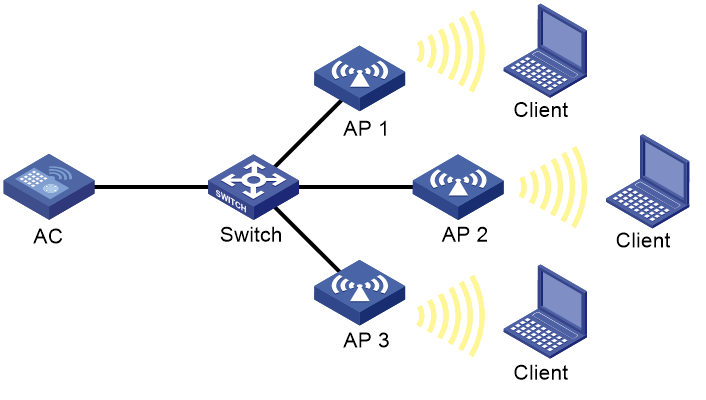
Example: Configuring periodic auto-DFS
Network configuration
As shown in Figure 10, configure periodic auto-DFS to adjust channels for radios of the APs when a channel adjustment trigger condition is met. Add radio 1 of AP 1 to an RRM holddown group to avoid frequent channel adjustments.

Procedure
# Establish a CAPWAP tunnel between the AC and each AP. For more information, see AP Management Configuration Guide. (Details not shown.)
# Enable auto-DFS for AP ap1 and set the auto-DFS mode to periodic.
<AC> system-view
[AC] wlan ap ap1 model WA6320
[AC-wlan-ap-ap1] radio 1
[AC-wlan-ap-ap1-radio-1] rrm
[AC-wlan-ap-ap1-radio-1-rrm] calibrate-channel self-decisive enable
[AC-wlan-ap-ap1-radio-1-rrm] calibrate-channel mode periodic
# Configure DFS trigger parameters.
[AC-wlan-ap-ap1-radio-1-rrm] crc-error-threshold 20
[AC-wlan-ap-ap1-radio-1-rrm] channel-usage-threshold percent 70
[AC-wlan-ap-ap1-radio-1-rrm] calibrate-channel interference-threshold percent 75
[AC-wlan-ap-ap1-radio-1-rrm] tolerance-level 20
[AC-wlan-ap-ap1-radio-1-rrm] quit
[AC-wlan-ap-ap1-radio-1] quit
[AC-wlan-ap-ap1] quit
# Create RRM holddown group 10.
[AC] wlan rrm-calibration-group 10
# Add radio 1 of AP ap1 to RRM holddown group 10.
[AC-wlan-rc-group-10] ap name ap1 radio 1
# Set the channel holddown time to 600 minutes.
[AC-wlan-rc-group-10] channel holddown-time 600
# Configure auto-DFS for AP 2 and AP 3 in the same way auto-DFS is configured for AP 1. (Details not shown.)
Verifying the configuration
# Execute the display wlan rrm-status ap all command. Verify that the working channels for radios of the APs change when a channel adjustment trigger condition is met and the calibration interval is reached. (Details not shown.)
Use the display wlan rrm-history ap all command to view the channel adjustment reason. (Details not shown.)
# Verify that the channel for radio 1 on AP 1 remains unchanged within 600 minutes after the first DFS. (Details not shown.)
Example: Configuring scheduled auto-DFS
Network configuration
As shown in Figure 11, configure scheduled auto-DFS to adjust channels for radios of the APs when a channel adjustment trigger condition is met.
Procedure
# Establish a CAPWAP tunnel between the AC and each AP. For more information, see AP Management Configuration Guide. (Details not shown.)
# Create a time range.
<AC> system-view
[AC] time-range time1 from 15:20 2015/04/17 to 18:20 2015/04/17
# Create a job and assign commands to the job.
[AC] scheduler job calibratechannel
[AC-job-calibratechannel] command 1 system-view
[AC-job-calibratechannel] command 2 wlan ap ap1
[AC-job-calibratechannel] command 3 radio 1
[AC-job-calibratechannel] command 4 rrm
[AC-job-calibratechannel] command 5 calibrate-channel pronto
[AC-job-calibratechannel] quit
# Create a schedule and assign the job to the schedule.
[AC] scheduler schedule schedule1
[AC-schedule-schedule1] job calibratechannel
# Specify an execution date and time for the schedule.
[AC-schedule-schedule1] time at 20:20 2015/04/17
[AC-schedule-schedule1] quit
# Enable auto-DFS on AP ap1 and set the auto-DFS mode to scheduled.
[AC] wlan ap ap1
[AC-wlan-ap-ap1] radio 1
[AC-wlan-ap-ap1-radio-1] rrm
[AC-wlan-ap-ap1-radio-1-rrm] calibrate-channel self-decisive enable
[AC-wlan-ap-ap1-radio-1-rrm] calibrate-channel mode scheduled
# Configure AP ap1 to perform channel monitoring during time range time1.
[AC-wlan-ap-ap1-radio-1-rrm] calibrate-channel monitoring time-range time1
# Configure auto-DFS attributes.
[AC-wlan-ap-ap1-radio-1-rrm] crc-error-threshold 10
[AC-wlan-ap-ap1-radio-1-rrm] channel-usage-threshold percent 70
[AC-wlan-ap-ap1-radio-1-rrm] calibrate-channel interference-threshold percent 75
[AC-wlan-ap-ap1-radio-1-rrm] tolerance-level 15
[AC-wlan-ap-ap1-radio-1-rrm] quit
# Configure auto-DFS for AP 2 and AP 3 in the same way auto-DFS is configured for AP 1. (Details not shown.)
Verifying the configuration
# Execute the display wlan rrm-status ap all command. Verify that the working channels for radios of the APs change when a channel adjustment trigger condition is met and the calibration interval is reached. (Details not shown.)
Use the display wlan rrm-history ap all command to view the channel adjustment reason. (Details not shown.)
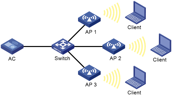
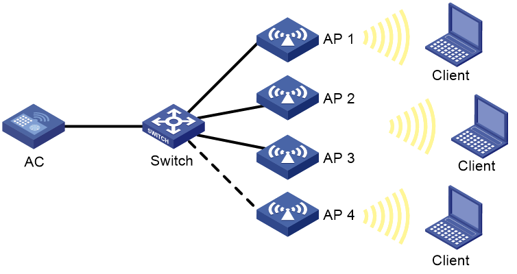
Example: Configuring auto-TPC
Network configuration
As shown in Figure 12, configure auto-TPC and set the adjacency factor to 3 to enable the AC to perform auto-TPC when AP 4 joins. Add radio 1 of AP 1 to an RRM holddown group to avoid frequent power adjustments.
Procedure
# Establish a CAPWAP tunnel between the AC and each AP. For more information, see AP Management Configuration Guide. (Details not shown.)
# Enable auto-TPC for AP ap1.
<AC> system-view
[AC] wlan ap ap1 model WA6320
[AC-wlan-ap-ap1] radio 1
[AC-wlan-ap-ap1-radio-1] rrm
[AC-wlan-ap-ap1-radio-1-rrm] calibrate-power self-decisive enable
# Configure TPC trigger parameters.
[AC-wlan-ap-ap1-radio-1-rrm] adjacency-factor 3
[AC-wlan-ap-ap1-radio-1-rrm] calibrate-power threshold 80
[AC-wlan-ap-ap1-radio-1-rrm] calibrate-power min 1
[AC-wlan-ap-ap1-radio-1-rrm] quit
[AC-wlan-ap-ap1-radio-1] quit
[AC-wlan-ap-ap1] quit
# Create RRM holddown group 10.
[AC] wlan rrm-calibration-group 10
# Add radio 1 of AP ap1 to RRM holddown group 10.
[AC-wlan-rc-group-10] ap name ap1 radio 1
# Set the power holddown time to 100 minutes.
[AC-wlan-rc-group-10] power holddown-time 100
# Configure auto-TPC for AP 2, AP 3, and AP 4 in the same way auto-TPC is configured for AP 1. (Details not shown.)
Verifying the configuration
# Use the display wlan rrm-status ap all command to verify the following information:
· AP 1 increases its transmit power when AP 4 detects that the power of AP 1 is lower than the power adjustment threshold.
· AP 1 decreases its transmit power when AP 4 detects that the power of AP 1 is higher than the power adjustment threshold.
· The adjusted power of AP 1 is not lower than the minimum transmit power (1 dBm in this example).
# Verify that the power of radio 1 on AP 1 remains unchanged within 100 minutes after the first TPC. (Details not shown.)
Example: Configuring automatic bandwidth adjustment
Network configuration
As shown in Figure 13, configure automatic bandwidth adjustment for the AC to automatically adjust the bandwidth of a radio when the number of neighbor radios of that radio reaches the threshold for triggering automatic bandwidth adjustement.
Procedure
# Establish a CAPWAP tunnel between the AC and each AP. For more information, see AP Management Configuration Guide.(Details not shown.)
# Enable automatic bandwidth adjustment for all 5 GHZ radios on all APs.
<AC> system-view
[AC] wlan global-configuration
[AC-wlan-global-configuration] calibrate-bandwidth self-decisive enable
[AC-wlan-global-configuration] quit
# Set the interval for automatic bandwidth adjustment.
[AC] wlan rrm calibration-bandwidth interval 10
Verifying the configuration
# Use the display wlan rrm-history ap all command to verify that the AC adjusts the bandwidth of all 5 GHz radios automatically.
