- Table of Contents
-
- H3C G3&G5 Servers Storage Controller User Guide-6W109
- 00-Preface
- 01-Storage controller overview
- 02-Storage controller features
- 03-Configuring an embedded RSTe RAID controller
- 04-Configuring an NVMe VROC module
- 05-Configuring a P430 storage controller
- 06-Configuring a 1000 storage controller
- 07-Configuring a 9361, 9440, 9460, L460, P5408, or H5408 storage controller
- 08-Configuring an H460, P460, P2404 or P4408 storage controller
- 09-Configuring a 9300 storage controller
- 10-Configuring a 9311 storage controller
- 11-Configuring an LSI 9400 or 9500 series storage controller
- 12-Configuring a RAID-MARVELL-SANTACRUZ-LP-2i storage controller
- 13-Appendix A Troubleshooting storage controllers
- 14-Appendix B RAID arrays and fault tolerance
- Related Documents
-
| Title | Size | Download |
|---|---|---|
| 05-Configuring a P430 storage controller | 5.55 MB |
Configuring a RAID-P430-M1 or RAID-P430-M2 storage controller
|
|
NOTE: The BIOS screens might vary by the BIOS version. The screenshots in this chapter are for illustration only. |
About RAID-P430-M1 and RAID-P430-M2 storage controllers
The RAID-P430-M1 and RAID-P430-M2 storage controllers support 6-Gbps and 12-Gbps SAS/SATA data channels and caching, which greatly increases performance and data security. For more information about storage controller details and the supported cache, access http://www.h3c.com/en/home/qr/default.htm?id=66.
Features
Operating modes
The storage controller supports the following operating modes:
· RAID: expose raw mode—This is the default mode. In this mode, the system can identify and assign drive letters to both raw drives and member drives of RAID arrays.
· RAID: hide raw mode—In this mode, the system can identify and assign drive letters only to member drives of RAID arrays. Raw drives cannot be identified or used by the operating system.
· HBA mode—In this mode, physical drives are exposed as raw drives and RAID functions are disabled.
· Auto Volume mode—In this mode, physical drives with system partitions are exposed as raw drives. Physical drives without system partitions are configured as simple volumes.
· Simple Volume mode—In this mode, only non-redundant RAID arrays with the simple volume level (each contains only one drive) can be created. RAID arrays with other RAID levels cannot be created.
|
|
NOTE: Raw drives refer to drives that do not have RAID configuration. |
Before you configure RAID in RAID: expose raw or RAID: hide raw mode or set the controller operating mode to auto volume or simple volume mode, you must initialize target drives.
Before you configure the controller to operate in RAID: expose raw mode without RAID configuration or in HBA mode, you must uninitialize target drives.
For the new mode to take effect, restart the server after an operating mode change.
The operating system might fail to start up after the operating mode of the storage controller is changed. To resolve the issue, you can re-install the operating system. If the issue persists, contact Technical Support.
RAID levels
The supported RAID levels vary by storage controller model. For more information about the supported RAID levels of each storage controller, contact Technical Support.
Table 1 shows the minimum number of drives required by each RAID level and the maximum number of failed drives supported by each RAID level. For more information about RAID levels, see "Appendix B RAID arrays and fault tolerance."
Table 1 RAID levels and the numbers of drives for each RAID level
|
RAID level |
Min. drives required |
Max. failed drives |
|
RAID 0 |
2 |
0 |
|
RAID 1 |
2 |
1 |
|
RAID 1E |
3 |
1 |
|
RAID 5 |
3 |
1 |
|
RAID 6 |
4 |
2 |
|
RAID 10 |
4 |
n, where n is the number of RAID 1 arrays in the RAID 10 array. |
|
RAID 50 |
6 |
n, where n is the number of RAID 5 arrays in the RAID 50 array. |
|
RAID 60 |
8 |
2n, where n is the number of RAID 6 arrays in the RAID 60 array. |
|
Simple Volume |
1 |
0 |
Hot spare drives
You can configure hot spare drives to improve data security. A hot spare drive is a standby drive that does not store any data. When one or multiple drives in a redundant RAID fails, spare drives automatically replace the failed drives and rebuild the data of the failed drives.
The storage controller supports the following types of hot spare drives. For more information about hot spare drive types, see "Storage controller features."
· Global spare drive.
· Dedicated spare drive.
· Pooled spare drive.
Restrictions and guidelines for configuring RAID
· As a best practice, configure RAID with drives that do not contain RAID information.
· To build a RAID successfully and ensure RAID performance, make sure all drives in the RAID are the same type (HDDs or SSDs) and have the same connector type (SAS or SATA).
· For efficient use of storage, use drives that have the same capacity to build a RAID. If the drives have different capacities, the lowest capacity is used across all drives in the RAID.
· If you use one physical drive to create multiple RAIDs, RAID performance might decrease in addition to increased maintenance complexities.
High speed read/write cache
For the RAID-P430-M1 and RAID-P430-M2 storage controllers, you can enable caching on the storage controller by using ARCCONF commands. For more information, see "xxx."
Configuring RAID arrays in UEFI mode
This section describes how to configure RAID arrays through a storage controller in UEFI mode. For more information about how to enter the BIOS and set the boot mode to UEFI, see the BIOS user guide for the server.
RAID array configuration tasks at a glance
To configure RAID arrays in UEFI mode, perform the following tasks:
· Accessing the storage controller configuration screen
· Switching the storage controller operating mode
· (Optional.) Configuring hot spare drives
· (Optional.) Deleting RAID arrays
· (Optional.) Uninitializing drives
· (Optional.) Locating drives
· (Optional.) Erasing drives
· (Optional.) Restoring the default configuration for a storage controller
· (Optional.) Upgrading the storage controller firmware online
· (Optional.) Enabling RAID rebuilding
· (Optional.) Migrating RAID levels
· (Optional.) Expanding RAID capacity
Accessing the storage controller configuration screen
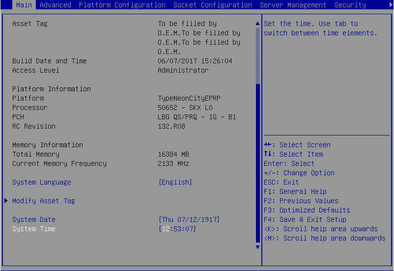
1. During server POST, press Delete, Esc, or F2 as prompted to open the BIOS setup screen as shown in Figure 1.
For how to navigate screens and modify settings, see the operation instructions at the lower right corner.
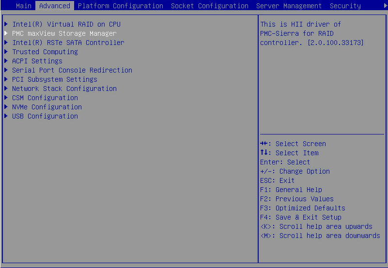
2. Select Advanced > Dynamic Device Configuration > PMC maxView Storage Manager or select Advanced > PMC maxView Storage Manager, and press Enter. Whether the Dynamic Device Configuration is displayed depends on the BIOS version.
3. On the screen as shown in Figure 3, select Scan For Controllers, and press Enter.
Figure 3 Selecting Scan For Controllers

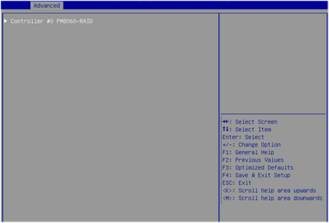
4. On the screen as shown in Figure 4, select Controller #0 PM8060-RAID, and press Enter.
Figure 4 Selecting Controller #0 PM8060-RAID
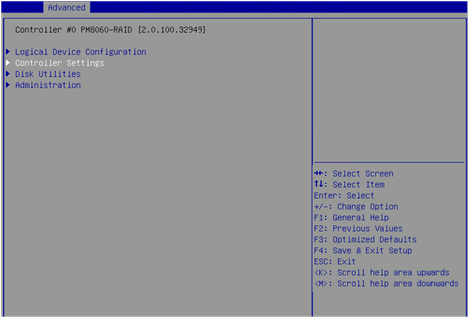
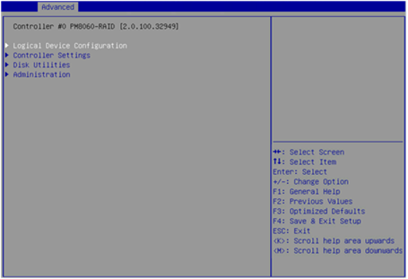
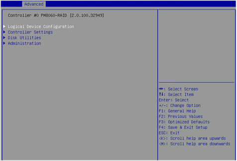
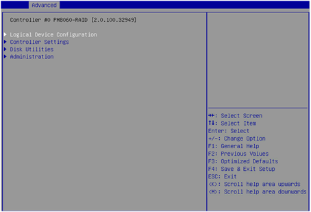
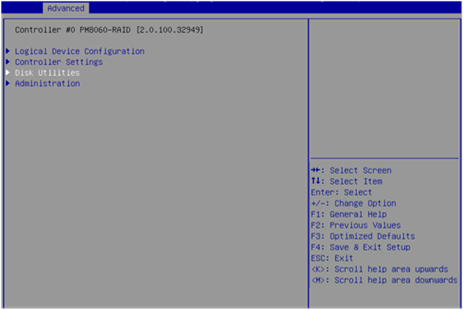
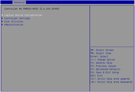
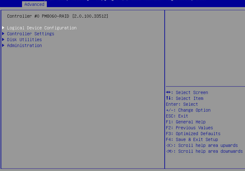
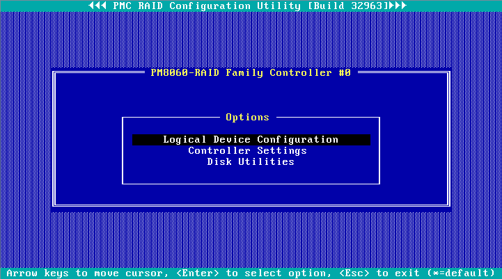
5. The storage controller configuration screen as shown in Figure 5 opens. This screen contains tasks as described in Table 2.
Figure 5 Storage controller configuration screen
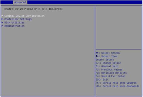
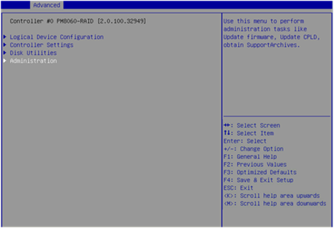
Table 2 Storage controller configuration tasks
|
Option |
Description |
|
Logical Device Configuration |
Select Logical Device Configuration to perform the following tasks: · Manage RAID arrays. · Create RAID arrays. · Initialize drives. · Erase drives. · Configure global hot spare drives. |
|
Controller Settings |
Select Controller Settings to perform the following tasks: · Modify the storage controller operating mode. · View the storage controller configuration information. · Restore the default configuration for a storage controller. |
|
Disk Utilities |
Select Disk Utilities to perform the following tasks: · View physical drive information. · Locate physical drives. · Format drives. |
|
Administration |
Select Administration to update the storage controller firmware. |
Switching the storage controller operating mode
1. On the storage controller configuration screen as shown in Figure 6, select Controller Settings, and press Enter.
Figure 6 Storage controller configuration screen
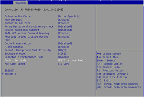
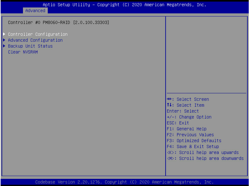
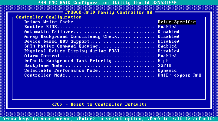
2. On the screen as shown in Figure 7, select Controller Configuration, and press Enter.
Figure 7 Controller Settings screen

3. On the screen as shown in Figure 8, select Controller Mode, and press Enter.
Figure 8 Controller Configuration screen
4. On the screen as shown in Figure 9, select a storage controller operating mode, and press Enter.
Table 3 describes the storage controller operating modes.
Figure 9 Selecting a storage controller operating mode
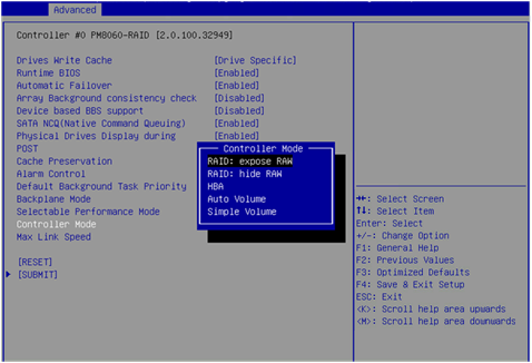
Table 3 Storage controller operating modes
|
Operating mode |
Description |
|
RAID: expose RAW |
All RAID functions can be used. Raw physical drives are exposed to the system. |
|
RAID: hide RAW |
All RAID functions can be used. Raw physical drives are not exposed to the system. |
|
HBA |
RAID functions are disabled. Raw physical drives are exposed to the system. Before setting this mode, you must delete all RAID arrays and hot spare drives, and perform the Uninitializing drives operation for all drives. |
|
Auto Volume |
In this mode, raw physical drives with system partitions are exposed to the system, and physical drives without system partitions are configured as simple volumes. Before setting this mode, you must delete all RAID arrays and hot spare drives in the system. |
|
Simple Volume |
In this mode, only non-redundant RAID arrays with the simple volume level (each contains only one drive) can be created. RAID arrays with other RAID levels cannot be created. Before setting this mode, you must delete all RAID arrays and hot spare drives in the system. |
Scanning drives
The storage controller might fail to timely recognize drives after the drives are hot swapped. To solve this problem, you can scan drives.
To scan drives:
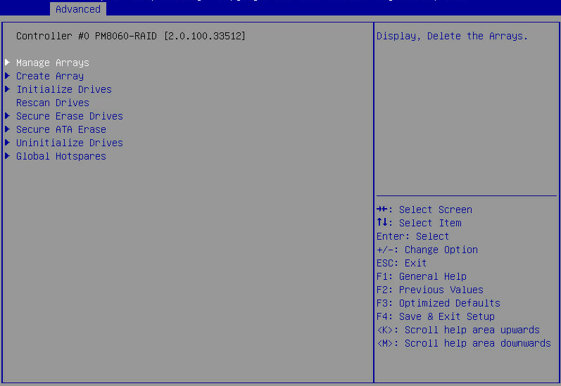
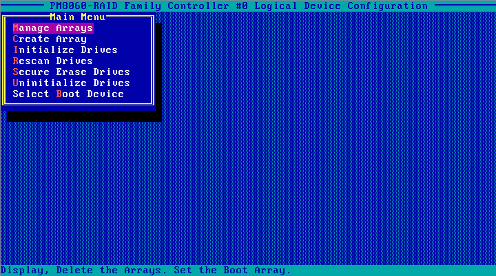
1. On the storage controller configuration screen as shown in Figure 10, select Logical Device Configuration, and press Enter.
Figure 10 Storage controller configuration screen
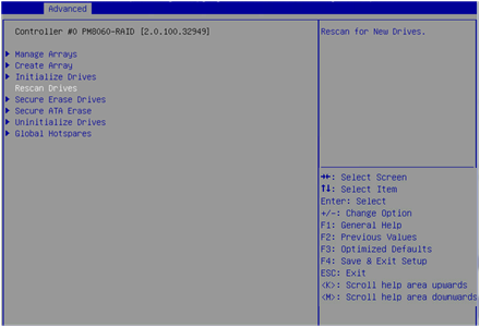
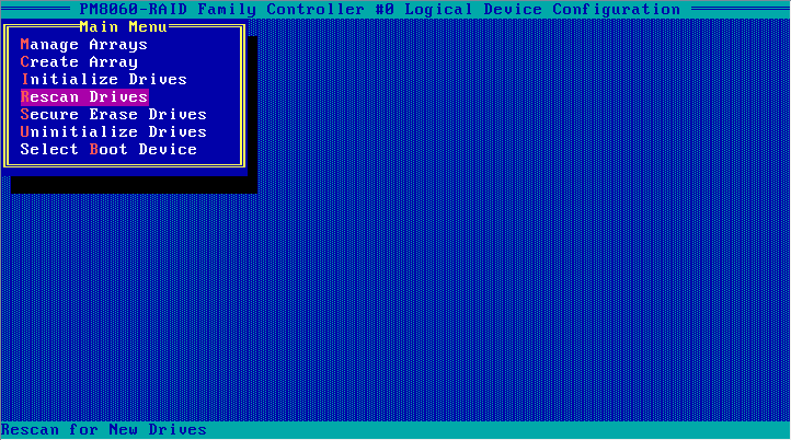
2. On the screen as shown in Figure 11, select Rescan Drives, and press Enter to scan drives.
Figure 11 Logical Device Configuration screen
Initializing drives
Initializing a drive is to divide a small partition from the drive for saving the RAID information. A raw drive must be initialized before it can be used for creating a RAID array or configured as a hot spare drive.
To initialize drives:
1. On the storage controller configuration screen as shown in Figure 12, select Logical Device Configuration, and press Enter.
Figure 12 Storage controller configuration screen

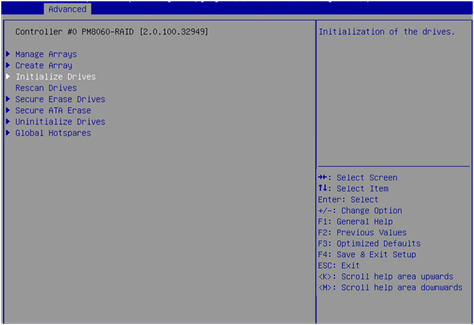
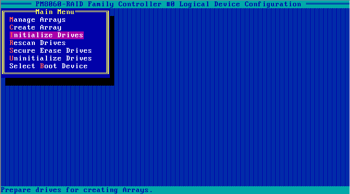
2. On the screen as shown in Figure 13, select Initialize Drives, and press Enter.
Figure 13 Logical Device Configuration screen
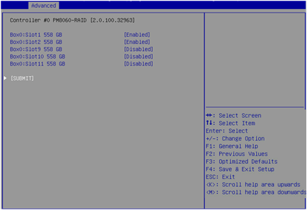
3. On the screen as shown in Figure 14, select the drives to be initialized. ([Enabled] following a drive means that the drive has been selected.) Then, select SUBMIT and press Enter.
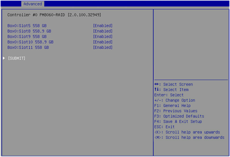
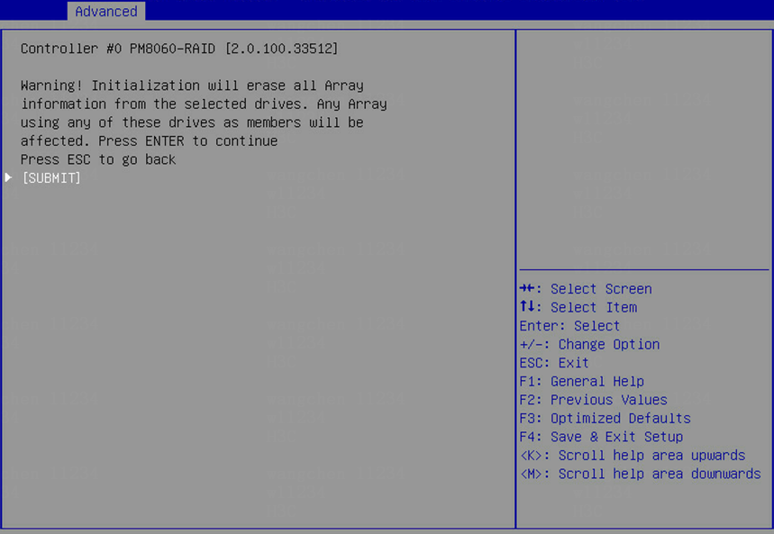
4. If the system prompts that the initiation will erase all array information from the selected drives and affect RAID arrays using these selected drives, perform one of the following tasks:
¡ To verify if the drives are correctly selected, press ESC to go back to the previous step.
¡ If you have selected correct drives, select SUBMIT and then press Enter.
Figure 15 Drive initiation risk warning screen
Configuring RAID arrays
1. On the storage controller configuration screen as shown in Figure 16, select Logical Device Configuration, and press Enter.
Figure 16 Storage controller configuration screen
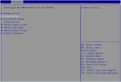
2. On the screen as shown in Figure 17, select Create Array, and press Enter.
Figure 17 Logical Device Configuration screen
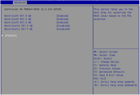
3. On the screen as shown in Figure 18, select the drives to be configured as a RAID array. ([Enabled] following a drive means that the drive has been selected.) Then, select PROCEED and press Enter.
A raw drive cannot be selected. To configure a RAID array for the drive, you must first initialize the drive. For more information about initializing drives, see "Initializing drives."
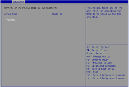
4. On the screen as shown in Figure 19, select Array type to set a RAID level, select PROCEED, and press Enter.
Figure 19 Selecting a RAID level
5. On the screen as shown in Figure 20, set the Array Label, Stripe Size, Array Size, Array Size Selection, Read Cache, Write Cache, and Create RAID via parameters, select SUBMIT, and press Enter to create the array.
Table 4 describes the configuration parameters.
Figure 20 Setting RAID parameters
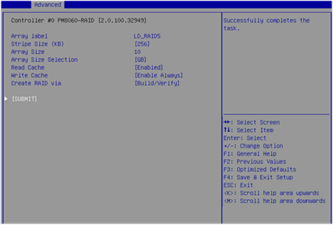
Table 4 Configuration parameters
|
Parameter |
Description |
|
Array Label |
RAID array name. The default is DefaultValue0. |
|
Stripe Size |
Strip size, which determines the data block size of a stripe on each drive. |
|
Array Size Selection |
RAID array capacity. |
|
Read Cache |
Read cache policy status. Options are Enabled and Disabled. |
|
Write Cache |
Write cache policy status: · Enable Always—Always enables the write cache. Without a supercapacitor installed, this status might cause data loss if power supply fails. · Enable With Backup Unit—Disables the write cache when the supercapacitor is absent or not ready. · Disabled—Disables the write cache. |
|
Create RAID via |
Operation after the RAID array is created. Options are as follows: · Quick Init—Performs initialization only when the corresponding stripe is accessed after the RAID array is created. · Skip Init—Establishes the RAID relationship immediately after the RAID array is created without clearing the data. · Build/Verify—Verifies the data for the drives after the RAID array is created to make the drives comply with the RAID level. · Clear—Clears the data of drives after the RAID array is created, which takes a long time. |
|
|
NOTE: If Build/Verify is selected, the read/write performance of a drive is low when the data of the drive is being verified. Do not perform any other tasks until the drive status becomes Optimal. |
6. On the storage controller configuration screen, select Logical Device Configuration > Manage Arrays, and press Enter, as shown in Figure 21.
Figure 21 Logical Device Configuration screen

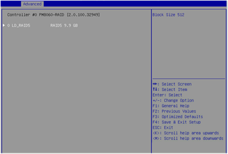
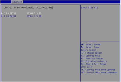
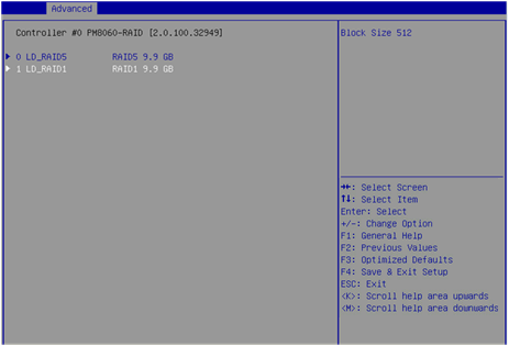
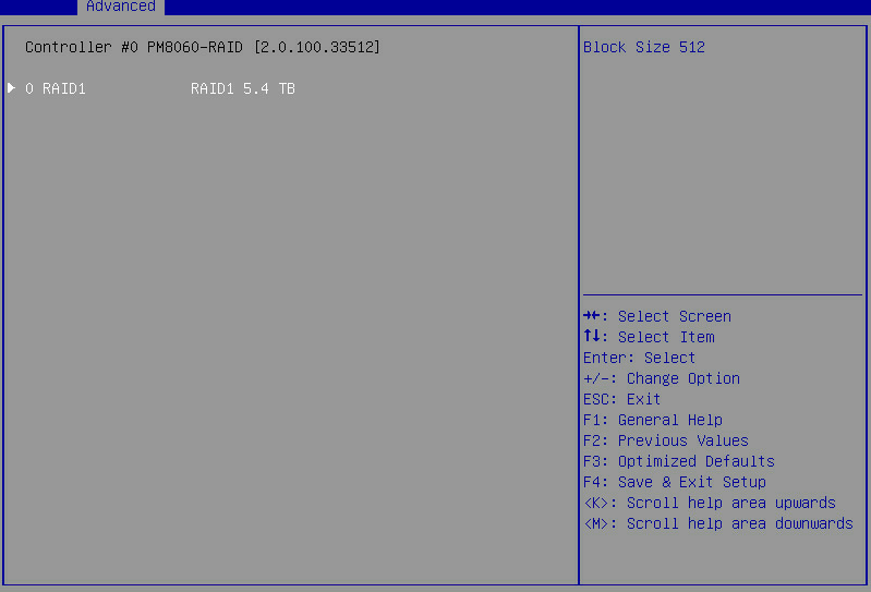
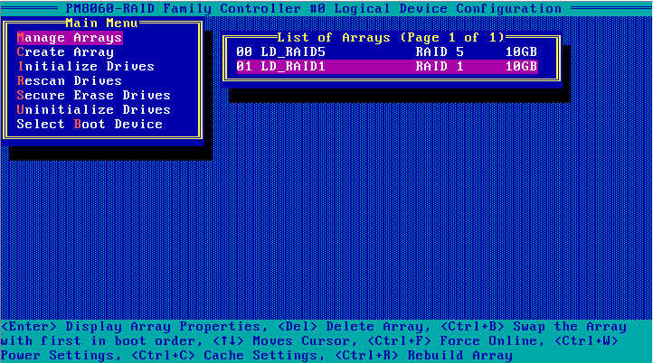
7. On the screen as shown in Figure 22, the created RAID array is displayed. Select the RAID array, and press Enter.
Figure 22 Manage Arrays screen
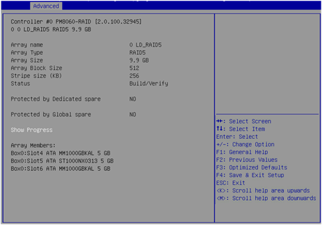
8. On the RAID management screen that opens, select Array Properties, and press Enter to view detailed information about the RAID array (including the RAID array name, RAID level, and member drives), as shown in Figure 23.
Figure 23 RAID array information screen
Configuring hot spare drives
After configuring a RAID array, you can configure hot spare drives for the RAID array to improve the data security. You can configure global or dedicated hot spare drives as needed.
Configuring global hot spare drives
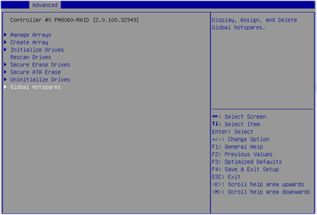
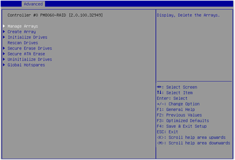
1. On the storage controller configuration screen as shown in Figure 24, select Logical Device Configuration, and press Enter.
Figure 24 Storage controller configuration screen
2. On the screen as shown in Figure 25, select Global Hotspares, and press Enter.
Figure 25 Logical Device Configuration screen
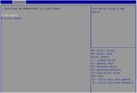
3. On the screen as shown in Figure 26, select Add Spares, and press Enter.
Figure 26 Global Hotspares configuration screen
|
|
NOTE: To delete a host spare drive, select Delete Spares on the screen as shown in Figure 26. |
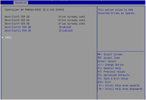
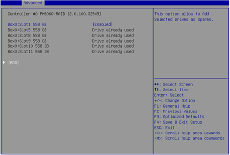
4. On the screen as shown in Figure 27, select the drives to be configured as global hot spare drives. ([Enabled] following a drive means that the drive has been selected.) Then, select ADD, and press Enter to configure the global hot spare drives.
|
|
NOTE: To configure a raw drive as a hot spare drive, you must first initialize the drive. For how to initialize drives, see "Initializing drives." |
Configuring dedicated hot spare drives
1. On the storage controller configuration screen, select Logical Device Configuration > Manage Arrays, and press Enter.
2. On the screen as shown in Figure 28, select the RAID array for which you want to configure dedicated hot spare drives, and press Enter.
Figure 28 Selecting a RAID array
3. On the screen as shown in Figure 29, select Failover Assignments, and press Enter.
Figure 29 Selecting Failover Assignments
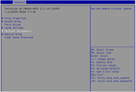
4. On the screen as shown in Figure 30, select Add Spares, and press Enter.
Figure 30 Failover Assignments

5. On the screen as shown in Figure 31, select the drives to be configured as dedicated hot spare drives. ([Enabled] following a drive means that the drive has been selected.) Then, select ADD, and press Enter to configure the dedicated hot spare drives.
Deleting RAID arrays
1. On the storage controller configuration screen as shown in Figure 32, select Logical Device Configuration, and press Enter.
Figure 32 Storage controller configuration screen

2. On the screen as shown in Figure 33, select Manage Arrays, and press Enter.
Figure 33 Logical Device Configuration screen
3. On the screen as shown in Figure 34, select the RAID array to be deleted, and press Enter.
Figure 34 Selecting the RAID array to be deleted
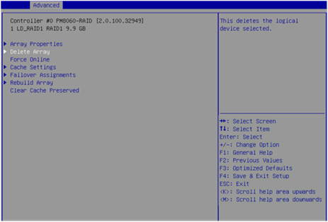
4. On the screen as shown in Figure 35, select Delete Array, and press Enter.
Figure 35 Selecting Delete Array
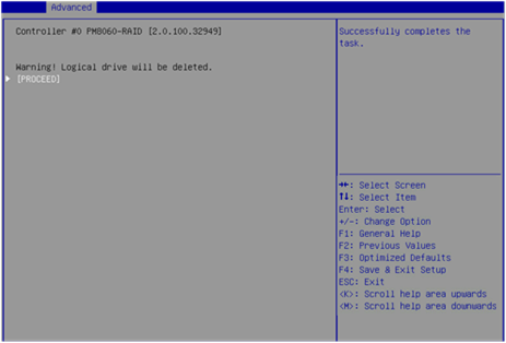
5. On the screen as shown in Figure 36, select PROCEED or SUBMIT, and press Enter to delete the selected RAID array.
Figure 36 Deleting a RAID array
Uninitializing drives
Perform this task to clear data, Adaptec metadata, and reserved space on drives, and remove the system partitions. After a drive in Ready state is uninitialized, it returns to the raw state.
To uninitialize drives:
1. On the storage controller configuration screen as shown in Figure 37, select Logical Device Configuration, and press Enter.
Figure 37 Storage controller configuration screen

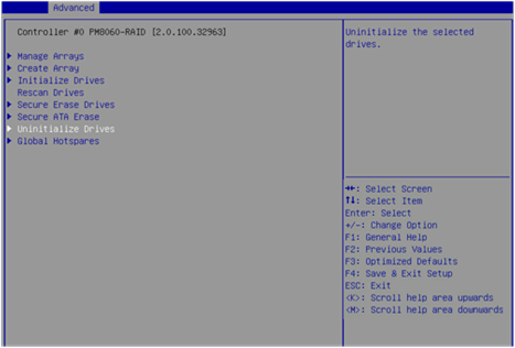
2. On the screen as shown in Figure 38, select Uninitialize Drives, and press Enter.
Figure 38 Logical Device Configuration screen
3. On the screen as shown in Figure 39, select the drives to be uninitialized. ([Enabled] following a drive means the drive has been selected.) Then, select SUBMIT, and press Enter to uninitialize the drives.
Locating drives
1. On the storage controller configuration screen as shown in Figure 40, select Disk Utilities, and press Enter.
Figure 40 Storage controller configuration screen
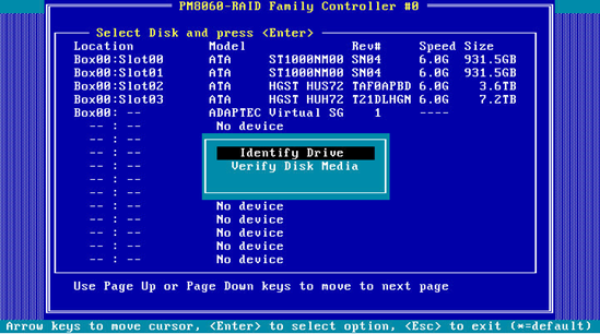
2. On the screen as shown in Figure 41, select the drive to be operated, and press Enter.
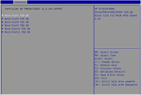
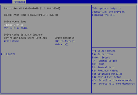
3. On the screen as shown in Figure 42, select an operation (Identify Drive in this example), and press Enter.
Table 5 describes the operation options.
Figure 42 Drive information display/operation screen
|
Option |
Description |
|
Verify Disk Media |
Verify the media of the drive. |
|
Identify Drive |
Locate the drive. With this operation performed for a drive, the Fault/UID LED on the drive backplane turns steady blue. |
|
Write Cache |
Set the write cache for the drive. |
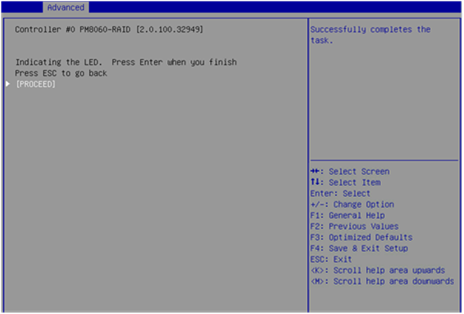
4. On the screen as shown in Figure 43, select PROCEED, and press Enter.
Then, the Fault/UID LED on the drive turns steady blue.
Erasing drives
|
|
WARNING! · To avoid data loss, do not enter the operating system and read or write the drives during the drive erasing process. · To avoid drive failure, do not perform any other operations during the drive erasing process. |
To erase drives:
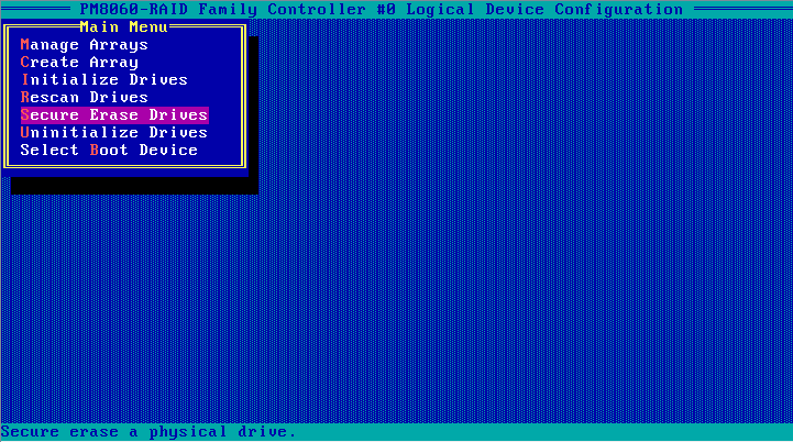
1. On the storage controller configuration screen as shown in Figure 44, select Logical Device Configuration, and press Enter.
Figure 44 Storage controller configuration screen
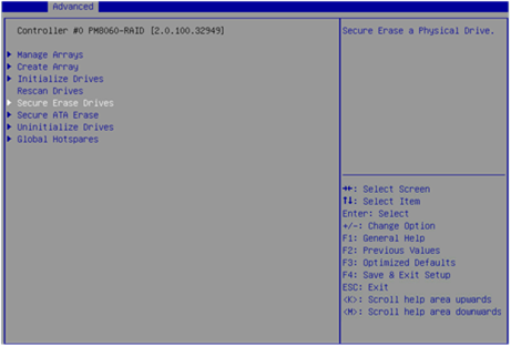
2. On the screen as shown in Figure 45, select Secure Erase Drives, and press Enter.
Figure 45 Selecting Secure Erase Drives
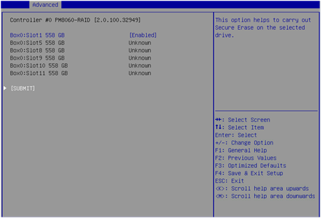
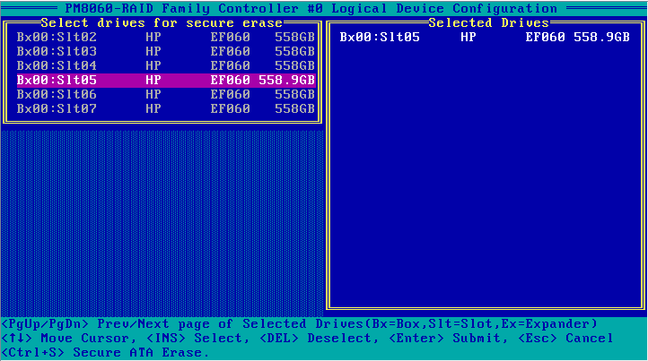
3. On the screen as shown in Figure 46, select the drives to be erased. ([Enabled] following a drive means that the drive has been selected.) Then, select SUBMIT, and press Enter.
Figure 46 Selecting the drives to be erased
4. On the screen as shown in Figure 47, select PROCEED or SUBMIT, and press Enter to erase the drives.
Restoring the default configuration for a storage controller
1. On the storage controller configuration screen as shown in Figure 48, select Controller Settings, and press Enter.
Figure 48 Storage controller configuration screen

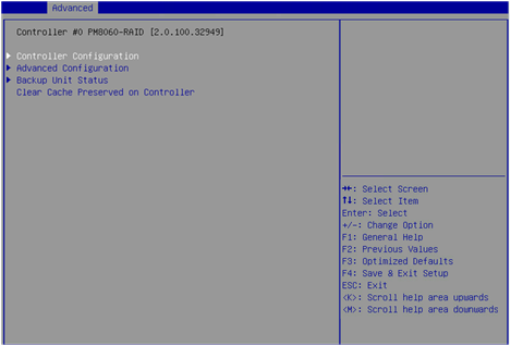
2. On the screen as shown in Figure 49, select Controller Configuration, and press Enter.
Figure 49 Controller Settings screen
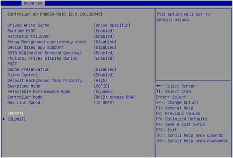
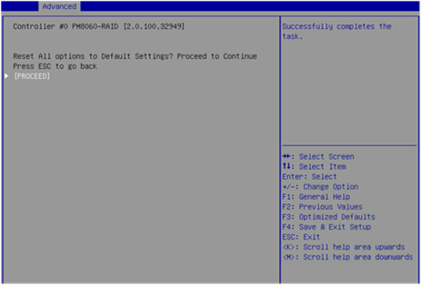
3. On the screen as shown in Figure 50, you can view the basic configuration of the storage controller. Select RESET, and press Enter.
|
|
IMPORTANT: The backplane mode sets the LED lighting policy. After the storage controller configuration is restored to the default, the LED lighting policy becomes IBPI, which causes the LED to operate abnormally. You must set the LED lighting policy to SGPIO. |
Figure 50 Controller Configuration screen
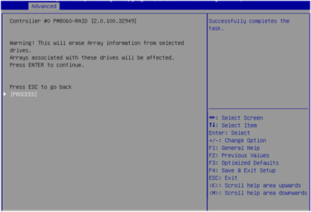
4. On the screen as shown in Figure 51, select PROCEED or SUBMIT, and press Enter to restore the storage controller configuration to the default.
Figure 51 Restoring the storage controller configuration to the default
Upgrading the storage controller firmware online
1. On the storage controller configuration screen as shown in Figure 52, select Administration, and press Enter.
Figure 52 Storage controller configuration screen
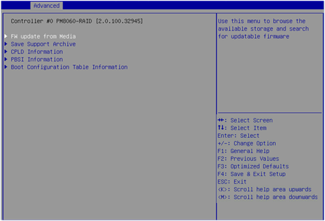
2. On the screen as shown in Figure 53, select FW update from Media, and press Enter.
Figure 53 Administration screen
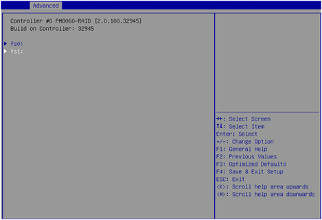
3. On the screen as shown in Figure 54, select the device where the update file resides (fs1 in this example), and press Enter.
Figure 54 Selecting the device where the update file resides
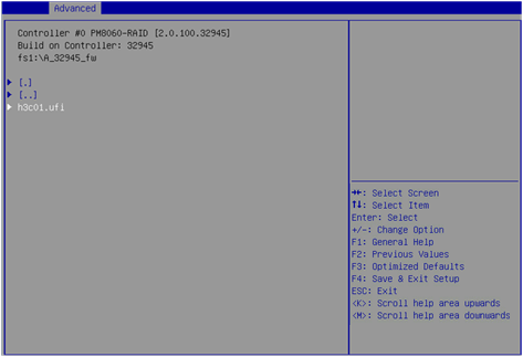
4. On the screen as shown in Figure 55, select the .ufi file and press Enter.
Figure 55 Selecting the update file
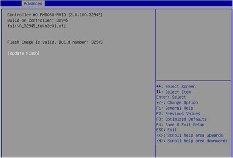
5. On the screen as shown in Figure 56, select Update Flash, and press Enter to start the update process. Wait until the update process is complete.
Figure 56 Selecting Update Flash
6. After the update is complete, press F4. On the dialog box that opens, select Yes to reboot the device and make the update take effect.
Enabling RAID rebuilding
If hot spare drives are not configured, you can perform this task to enable RAID rebuilding manually. If hot spare drives are configured, the system performs RAID rebuilding as required after a drive replacement, which is not affected by the status of the RAID rebuilding feature.
To enable RAID rebuilding:
1. On the storage controller configuration screen as shown in Figure 57, select Controller Settings, and press Enter.
Figure 57 Storage controller configuration screen

2. On the screen as shown in Figure 58, select Controller Configuration, and press Enter.
Figure 58 Controller Settings screen
3. On the screen as shown in Figure 59, set Automatic Failover to Enabled.
Figure 59 Controller Configuration screen
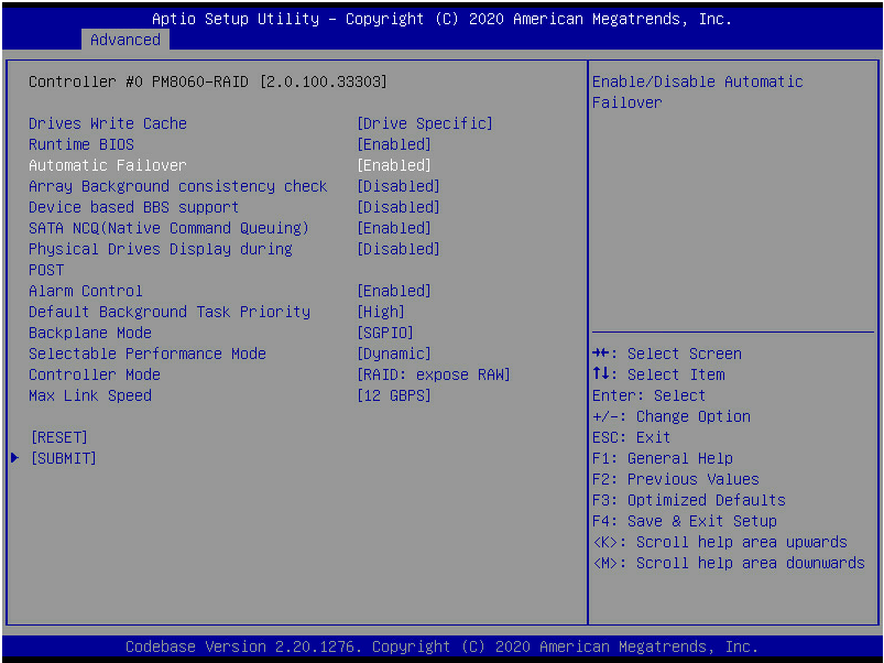
4. Select SUBMIT and then press Enter.
Migrating RAID levels
You can perform RAID level migration for the RAID-P430-M1 and RAID-P430-M2 storage controllers only by using ARCCONF commands. For more information, see "xxx."
Expanding RAID capacity
You can perform RAID capacity expansion for the RAID-P430-M1 and RAID-P430-M2 storage controllers only by using ARCCONF commands. For more information, see "xxx" and "xxx."
Forcing logical drives to come online
If the number of offline drives exceeds the tolerance range of the logical drive fault-tolerant method, the management tool interface will display the logical disk state as Failed. In this case, you can use the Force Online function to force the logical drives to come online.
|
|
CAUTION: The Force Online operation sets all available drives to the Optimal state without considering data consistency among member drives of a logical drive. Even if the Force Online operation is successful, if one or more drives contain outdated data, all data on this logical device may be changed or lost. |
To force logical drives to come online:
1. On the storage controller screen, select Logical Device Configuration and then press Enter.
Figure 60 Storage controller screen
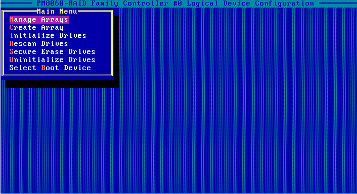
2. Select Manage Arrays and then press Enter.
Figure 61 Logical Device Configuration screen
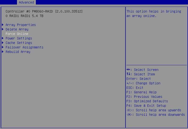
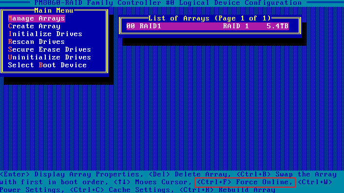
3. Select a RAID array in Failed state, and then press Enter.
Figure 62 Manage Arrays screen
4. Select Force Online and then press Enter.
Figure 63 Force Online
Configuring RAID arrays in legacy mode
This section describes how to configure RAID arrays through a storage controller in legacy mode. For more information about how to enter the BIOS and set the boot mode to legacy, see the BIOS user guide for the server.
RAID array configuration tasks at a glance
To configure RAID arrays in legacy mode, perform the following tasks:
· Accessing the storage controller configuration screen
· Switching the storage controller operating mode
· (Optional.) Configuring boot options
· (Optional.) Deleting RAID arrays
· (Optional.) Uninitializing drives
· (Optional.) Erasing drives
· (Optional.) Locating drives
· (Optional.) Modifying storage controller settings
Accessing the PMC RAID management screen
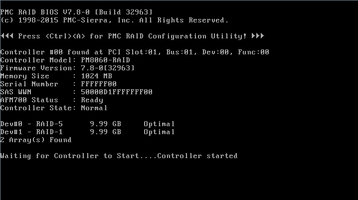
1. During server POST, press Ctrl+A when the screen as shown in Figure 64 opens.
Figure 64 Pressing Ctrl+A as prompted during server POST
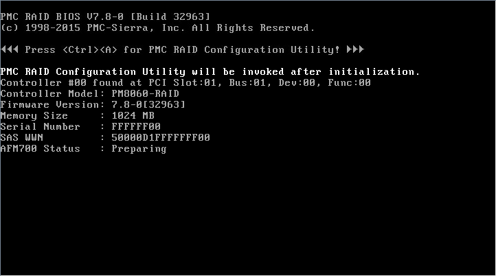
2. The screen as shown in Figure 65 opens, which displays the storage controller version and status information.
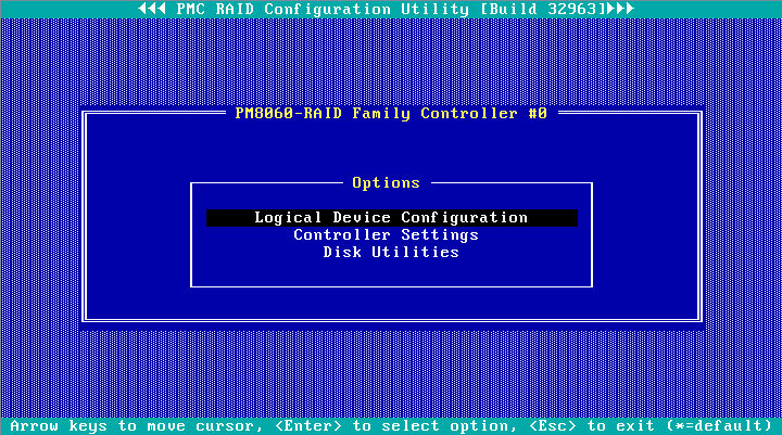
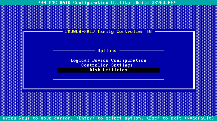
3. The PMC RAID management screen as shown in Figure 66 opens.
Table 6 describes the configuration options. For how to navigate screens and modify settings, see the operation instructions at the bottom.
Figure 66 PMC RAID management screen
|
Option |
Description |
|
Logical Device Configuration |
Select Logical Device Configuration to perform the following tasks: · Manage RAID arrays. · Create RAID arrays. · Initialize or uninitialize drives. · Erase drives. · Configure boot options. |
|
Controller Settings |
Select Controller Settings to perform the following tasks: · Modify the storage controller operating mode. · Restore the default configuration for a storage controller. |
|
Disk Utilities |
Select Disk Utilities to perform the following tasks: · Format drives. · Locate physical drives. |
Switching the storage controller operating mode
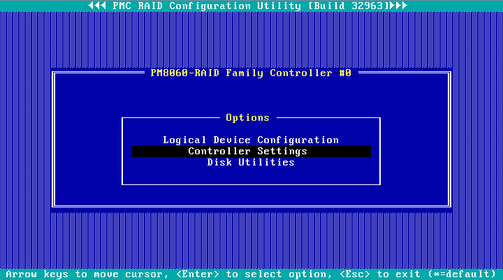
1. On the PMC RAID management screen as shown in Figure 67, select Controller Settings, and press Enter.
Figure 67 PMC RAID management screen
2. On the screen as shown in Figure 68, select Controller Configuration, and press Enter.
Figure 68 Controller Settings screen

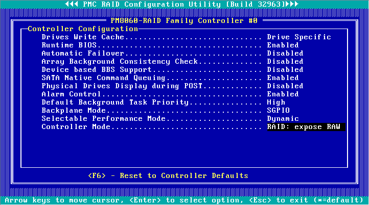
3. On the screen as shown in Figure 69, select Controller Mode, and press Enter.
Figure 69 Controller Configuration screen
4. On the screen as shown in Figure 70, select a storage controller operating mode (Table 7 describes the storage controller operating modes), and press Enter.
Figure 70 Selecting a storage controller operating mode
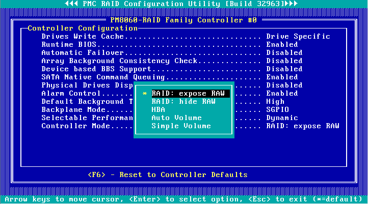
Table 7 Storage controller operating modes
|
Operating mode |
Description |
|
RAID: expose RAW |
All RAID functions can be used. Raw physical drives are exposed to the system. |
|
RAID: hide RAW |
All RAID functions can be used. Raw physical drives are not exposed to the system. |
|
HBA |
RAID functions are disabled. Raw physical drives are exposed to the system. Before setting this mode, you must delete all RAID arrays and hot spare drives, and perform the Uninitializing drives operation for all drives. |
|
Auto Volume |
In this mode, raw physical drives with system partitions are exposed to the system, and physical drives without system partitions are configured as simple volumes. Before setting this mode, you must delete all RAID arrays and hot spare drives in the system. |
|
Simple Volume |
In this mode, only non-redundant RAID arrays with the simple volume level (each contains only one drive) can be created. RAID arrays with other RAID levels cannot be created. Before setting this mode, you must delete all RAID arrays and hot spare drives in the system. |
5. Reboot the operating system to make the storage controller operating mode configuration take effect.
Scanning drives
The storage controller might fail to timely recognize drives after the drives are hot swapped. To solve this problem, you can scan drives.
To scan drives:
1. On the PMC RAID management screen as shown in Figure 71, select Logical Device Configuration, and press Enter.
Figure 71 PMC RAID management screen
2. On the screen as shown in Figure 72, select Rescan Drives, and press Enter.
Figure 72 Logical Device Configuration screen
Initializing drives
Initializing a drive is to divide a small partition in the drive for saving the RAID information. A raw drive must be initialized before it is used for creating a RAID array or configured as a hot spare drive.
To initialize drives:
1. On the PMC RAID management screen as shown in Figure 73, select Logical Device Configuration, and press Enter.
Figure 73 PMC RAID management screen

2. On the screen as shown in Figure 74, select Initialize Drives, and press Enter.
Figure 74 Logical Device Configuration screen
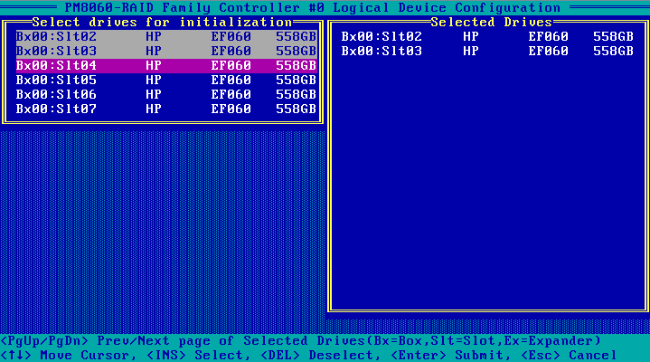
3. On the screen as shown in Figure 75, navigate to the drive that you want to initialize, and press Insert to select the drive. Repeat this step to select more drives. Then, press Enter.
Figure 75 Selecting and initializing drives
Configuring RAID arrays
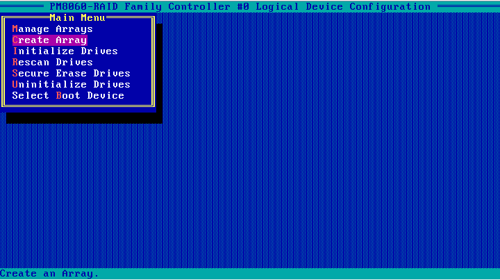
1. On the PMC RAID management screen as shown in Figure 76, select Logical Device Configuration, and press Enter.
Figure 76 PMC RAID management screen

2. On the screen as shown in Figure 77, select Create Array, and press Enter.
Figure 77 Logical Device Configuration screen
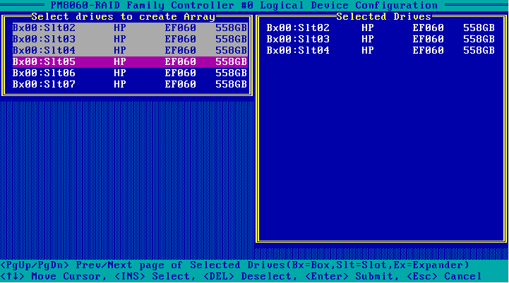
3. On the screen as shown in Figure 78, navigate to the drive to be configured for a RAID array, and press Insert to select the drive. Repeat this step to select more drives. Then, press Enter.
4. On the screen as shown in Figure 79, set the Array Type, Array Label, Array Size, Stripe Size, Read Caching, Write Caching, and Create RAID via parameters, select Done, and press Enter.
Table 8 describes the parameters.
Figure 79 Setting RAID parameters
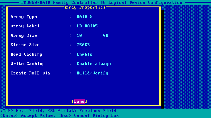
Table 8 Configuration parameters
|
Parameter |
Description |
|
Array Type |
Select a RAID level, which determines the performance, fault tolerance capability, and capacity of the logical drive. |
|
Array Label |
RAID array name, which must be manually entered. |
|
Array Size |
RAID array capacity. |
|
Stripe Size |
Strip size, which determines the data block size of a stripe on each drive. |
|
Read Caching |
Read cache. |
|
Write Caching |
Write cache. |
|
Create RAID via |
Select a method for initializing the RAID array. |
5. After the RAID array is created, select Manage Arrays, and press Enter on the screen as shown in Figure 80.
Figure 80 Selecting Manage Arrays
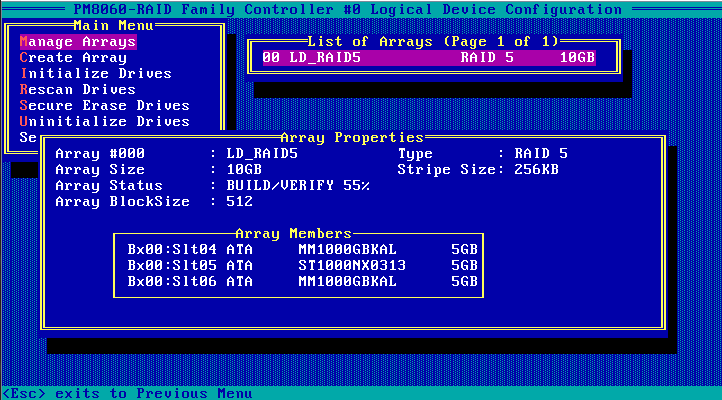
6. On the screen as shown in Figure 81, select the RAID array that you want to view, and press Enter to view the RAID array details (including the RAID array name, RAID level, and member drives).
Figure 81 Viewing RAID array information
Configuring boot options
This section describes how to configure boot options. You can configure a logical drive or physical drive as the first boot option.
Configuring a logical drive as the first boot option
Only a logical drive in Optimal state can be configured as the first boot option.
To configure a logical drive as the first boot option:
1. On the PMC RAID management screen as shown in Figure 82, select Logical Device Configuration, and press Enter.
Figure 82 PMC RAID management screen

2. On the screen as shown in Figure 83, select Manage Arrays, and press Enter.
Figure 83 Logical Device Configuration screen

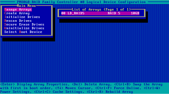
3. On the screen as shown in Figure 84, select a RAID array, and press Ctrl+B to configure it as the first boot option.
Figure 84 Selecting the RAID array to be configured as the first boot option

Configuring a physical drive as the first boot option
Only a raw physical drive can be configured as the first boot option. To configure a physical drive in any other state as the first boot option, you must first perform the Uninitializing drives operation for the drive.
In legacy mode, after you configure the storage controller to operate in HBA mode, you must configure a raw drive as the first boot option. Otherwise, the operating system cannot be installed or started.
To configure a physical drive as the first boot option:
1. On the PMC RAID management screen, select Logical Device Configuration, and press Enter.
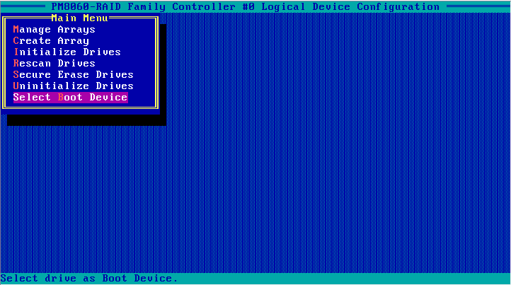
2. On the screen as shown in Figure 85, select Select Boot Device, and press Enter.
Figure 85 Logical Device Configuration screen
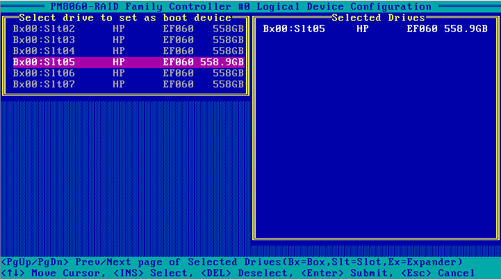
3. On the screen as shown in Figure 86, navigate to the drive to be used as the boot device, press Insert to select the drive, and press Enter.
Deleting RAID arrays
1. On the PMC RAID management screen as shown in Figure 87, select Logical Device Configuration, and press Enter.
Figure 87 PMC RAID management screen

2. On the screen as shown in Figure 88, select Manage Arrays, and press Enter.
Figure 88 Logical Device Configuration screen
3. On the screen as shown in Figure 89, select the RAID array to be deleted, and press Delete to delete it.
Figure 89 Deleting a RAID array
Uninitializing drives
|
|
IMPORTANT: When the storage controller operating mode is HBA, you cannot uninitialize drives. To uninitialize these drives, you must first set the storage controller operating mode to RAID: hide RAW, RAID: expose RAW, Auto Volume, or Simple Volume. |
Perform this task to clear data, Adaptec metadata, and reserved space on drives, and remove the system partitions. After a drive in Ready state is uninitialized, it returns to the raw state.
To uninitialize drives:
1. On the PMC RAID management screen, select Logical Device Configuration, and press Enter.
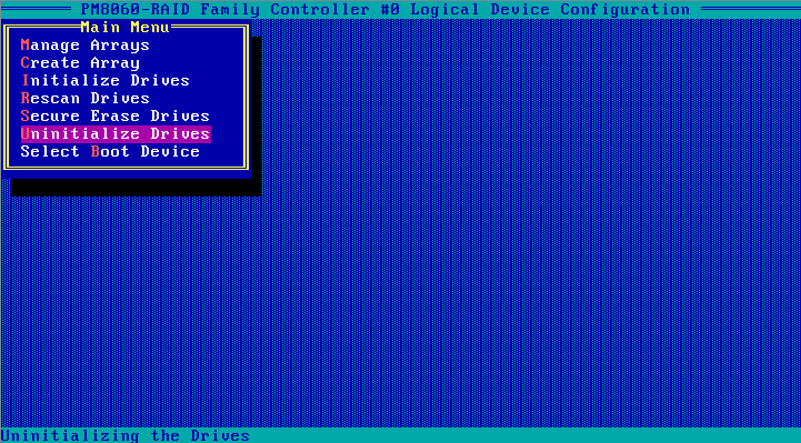
2. On the screen as shown in Figure 90, select Uninitialize Drives, and press Enter.
Figure 90 Logical Device Configuration screen
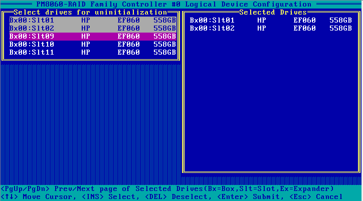
3. On the screen as shown in Figure 91, navigate to the drive that you want to uninitialize, and press Insert to select the drive. Repeat this step to select more drives. Then, press Enter to uninitialize the selected drives.
Figure 91 Selecting and uninitializing drives
Erasing drives
|
|
CAUTION: · To avoid data loss, do not enter the operating system and read or write the drives during the drive erasing process. · To avoid drive failure, do not perform any other operating during the drive erasing process. |
To erase drives:
1. On the PMC RAID management screen as shown in Figure 92, select Logical Device Configuration, and press Enter.
Figure 92 PMC RAID management screen

2. On the screen as shown in Figure 93, select Secure Erase Drives, and press Enter.
Figure 93 Logical Device Configuration screen
3. On the screen as shown in Figure 94, navigate to the drive that you want to erase, and press Insert to select the drive. Repeat this step to select more drives. Then, press Enter.
Locating drives
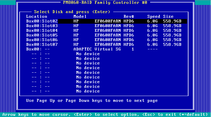
1. On the PMC RAID management screen as shown in Figure 95, select Disk Utilities, and press Enter.
Figure 95 PMC RAID management screen
2. On the screen as shown in Figure 96, you can view the drive information. Select the drive to be operated, and press Enter.
Figure 96 Disk Utilities screen
3. On the screen as shown in Figure 97, select Identify Drive and press Enter. The Fault/UID LED on the drive turns steady blue.
Modifying storage controller settings
Perform this task to view the storage controller configuration information, restore the default configuration for the storage controller, and modify the storage controller settings.
To modify storage controller settings:
1. On the PMC RAID management screen as shown in Figure 98, select Controller Settings, and press Enter.
Figure 98 PMC RAID management screen

2. On the screen as shown in Figure 99, select Controller Configuration, and press Enter.
Figure 99 Controller Settings screen

3. On the screen as shown in Figure 100, you can view or modify the basic configuration information for the storage controller. Press F6 to restore the default configuration for the storage controller.
You can set the storage controller operating mode, backplane mode, whether to display physical drives during POST, and RAID rebuilding status.
|
|
NOTE: Backplane Mode is used to set the LED lighting policy. After restoring the default configuration of the storage controller, the LED lighting policy changes to IBPI, which may cause the LED status display to not comply with the specification. You must set the LED lighting policy to SGPIO. |
Figure 100 Controller Configuration screen
Forcing logical drives to come online
If the number of offline drives exceeds the tolerance range of the logical drive fault-tolerant method, the management tool interface will display the logical disk state as Failed. In this case, you can use the Force Online function to force the logical drives to come online.
|
|
CAUTION: The Force Online operation sets all available drives to the Optimal state without considering data consistency among member drives of a logical drive. Even if the Force Online operation is successful, if one or more drives contain outdated data, all data on this logical device may be changed or lost. |
To force logical drives to come online:
1. On the storage controller screen, select Logical Device Configuration and then press Enter.
Figure 101 Storage controller screen

2. Select Manage Arrays and then press Enter.
Figure 102 Logical Device Configuration screen
3. Select a RAID array in Failed state, press Enter, and then press Ctrl+F.
Figure 103 Manage Arrays screen
Downloading and installing ARCCONF
This section introduces the download and installation steps of the OS command line tool. You can use the OS command line tool to manage storage controllers during normal server operation without restarting the server.
Downloading ARCCONF
1. Access https://www.h3c.com/cn/BizPortal/DownLoadAccessory/DownLoadAccessoryFilt.aspx.
2. Download the installation package and release notes for the corresponding storage controller firmware as instructed.
3. Decompress the installation package to obtain the ARCCONF tool package for different operating systems.
Installing ARCCONF
See the release notes to install ARCCONF for the corresponding operating system.
Commonly-used commands in ARCCONF
This section describes the usage and examples of commonly used commands in ARCCONF. You can use ARCCONF commands to manage storage controllers during normal server operation without restarting the server.
Upgrading the storage controller firmware
Perform this task to upgrade the storage controller firmware.
Syntax
arcconf romupdate controller_id fwfile
Parameters
controller_id: Specifies the ID of the storage controller.
fwfile: Specifies the name of the firmware file.
Examples
# Upgrade the storage controller firmware.
[root@localhost 007]# arcconf romupdate 1 REDWOODZ_2G01.ufi
Controllers found: 1
Are you sure you want to continue?
Press y, then ENTER to continue or press ENTER to abort: y
Updating controller 1 firmware...
Succeeded
You must restart the system for firmware updates to take effect.
Command completed successfully.
Viewing basic information about a storage controller
Perform this task to view basic information about a storage controller.
Syntax
arcconf list controller_id
Parameters
controller_id: Specifies the ID of the storage controller.
Examples
# View attributes of storage controller 1.
[root@localhost ~]# arcconf list 1
Controllers found: 1
----------------------------------------------------------------------
Controller information
----------------------------------------------------------------------
Controller ID : Status, Slot, Mode, Name, SerialNumber, WWN
----------------------------------------------------------------------
Controller 1: : Optimal, Slot Unknown, RAID (Expose RAW), PM8060-RAID , FADC8000, 5600B036FADC8000
----------------------------------------------------------------------
Logical device information
----------------------------------------------------------------------
Logical ID : Status (RAID, Interface, Size MB) Name
----------------------------------------------------------------------
No logical devices configured
----------------------------------------------------------------------
maxCache 3.0 information
----------------------------------------------------------------------
maxCache Logical ID : Status (RAID, Interface, Size MB) Name
----------------------------------------------------------------------
No maxCache 3.0 found
----------------------------------------------------------------------
Physical Device information
----------------------------------------------------------------------
Physical ID : State (Interface, BlockSize, SizeMB, Vendor, Model, Type) WWN, [Location]
----------------------------------------------------------------------
Physical 0,33 : Raw (Pass Through) (SATA, 512 Bytes, 5723166MB, ATA, ST6000NM0115-1YZ11 , Hard Drive) 5000C50ctor 0, Connector 1)]
Physical 0,34 : Raw (Pass Through) (SATA, 512 Bytes, 7630885MB, ATA, ST8000NM000A-2KE10 , Hard Drive) 5000C50ctor 0, Connector 1)]
Physical 0,35 : Raw (Pass Through) (SATA, 512 Bytes, 15259648MB, ATA, ST16000NM000G-2KH13, Hard Drive) 5000C5ector 0, Connector 1)]
Physical 0,36 : Raw (Pass Through) (SATA, 512 Bytes, 15259648MB, ATA, ST16000NM000G-2KH13, Hard Drive) 5000C5ector 0, Connector 1)]
Physical 0,37 : Raw (Pass Through) (SATA, 512 Bytes, 15259648MB, ATA, ST16000NM000G-2KH13, Hard Drive) 5000C5ector 0, Connector 1)]
Physical 2,0 : Ready (SES2, Not Applicable, Not Applicable, LSI, Cub, Enclosure Services Device) 500605B0000
Physical 2,1 : Ready (SES2, Not Applicable, Not Applicable, LSI, Cub, Enclosure Services Device) 500605B0000
Command completed successfully.
Viewing physical drive, array, LD, and storage controller information
Perform this task to view basic information about a storage controller.
Syntax
Table 9 View storage controller information
|
Command |
Function |
|
arcconf getconfig controller_id AD |
View storage controller information. |
|
arcconf getconfig controller_id LD |
View information about all the LD for a storage controller. |
|
arcconf getconfig controller_id LD LD_id |
View information about the specified LD. |
|
arcconf getconfig controller_id PD |
View information about all physical drives for a storage controller. |
|
arcconf getconfig controller_id PD channel_id device_id |
View information about the specified physical drive. |
|
arcconf getconfig controller_id AR |
View information about all arrays for a storage controller. |
|
arcconf getconfig controller_id AR AR_id |
View information about the specified array. |
Parameters
controller_id: Specifies the ID of the storage controller.
LD_id: Specifies the ID of a logical drive.
channel_id: Specifies the channel ID of a drive.
device_id: Specifies the device ID of a drive.
AR_id: Specifies the ID of an array.
Examples
# View information about all arrays.
[root@localhost ~]# ./arcconf getconfig 1 ar
Controllers found: 1
----------------------------------------------------------------------
Array Information
----------------------------------------------------------------------
Array Number 0
Name : A
Status : Ok
Interface : SATA SSD
Total Size : 305152 MB
Unused Size : 204800 MB
Block Size : 512 Bytes
Array Utilization : 32.77% Used, 67.23% Unused
Type : Data
Transformation Status : Not Applicable
Spare Rebuild Mode : Dedicated
SSD I/O Bypass : Disabled
--------------------------------------------------------
Array Logical Device Information
--------------------------------------------------------
Logical 0 : Optimal (1, Data, 49999 MB) LogicalDrv 0
--------------------------------------------------------
Array Physical Device Information
--------------------------------------------------------
Device 0 : Present (915715MB, SATA, SSD, Channel:0, Device:0) 18031A983BCA
Device 1 : Present (152627MB, SATA, SSD, Channel:0, Device:1) CVPR1461036N160DGN
--------------------------------------------------------
Array Hotspare Information
--------------------------------------------------------
Device 3 : Dedicated Hot-Spare (457862MB, SATA, SSD, Channel:0, Device:3) 2029E247 +
Command completed successfully.
[root@localhost ~]#
# View basic information about all LDs.
[root@localhost home]# arcconf getconfig 1 ld
Controllers found: 1
----------------------------------------------------------------------
Logical device information
----------------------------------------------------------------------
Logical Device number 0
Logical Device name : LogicalDrv 0
Disk Name : /dev/sdg
Block Size of member drives : 512 Bytes
Array : 0
RAID level : 1
Status of Logical Device : Optimal
Size : 457830 MB
Stripe-unit size : 256 KB
Full Stripe Size : 256 KB
Interface Type : SATA SSD
Device Type : Data
Boot Type : None
Heads : 255
Sectors Per Track : 32
Cylinders : 65535
Caching : Enabled
Mount Points : Not Mounted
LD Acceleration Method : Controller Cache
Volume Unique Identifier : 600508B1001C3F40059B7A4BF459DD3C
--------------------------------------------------------
Array Physical Device Information
--------------------------------------------------------
Device 8 : Present (457862MB, SATA, SSD, Connector:CN0, Enclosure:1, Slot:0) BTYF8316086G480BGN
Device 9 : Present (457862MB, SATA, SSD, Connector:CN0, Enclosure:1, Slot:1) BTYF95230EMQ480BGN
Command completed successfully.
# View basic information about all PDs.
[root@localhost home]# arcconf getconfig 1 pd
Controllers found: 1
----------------------------------------------------------------------
Physical Device information
----------------------------------------------------------------------
Device #0
Device is a Hard drive
State : Raw (Pass Through)
Block Size : 512 Bytes
Supported : Yes
Programmed Max Speed : SAS 12.0 Gb/s
Transfer Speed : SAS 12.0 Gb/s
Reported Channel,Device(T:L) : 0,0(0:0)
Reported Location : Enclosure 0, Slot 0(Connector 0)
Reported ESD(T:L) : 2,0(0:0)
Vendor : SEAGATE
Model : ST300MP0006
Firmware : N002
Serial number : WAE02RZM0000E74049PF
World-wide name : 5000C5009F4A36B0
Reserved Size : 0 KB
Total Size : 286102 MB
Write Cache : Disabled (write-through)
FRU : None
S.M.A.R.T. : No
S.M.A.R.T. warnings : 0
Power State : Full rpm
Supported Power States : Full rpm,Powered off
SSD : No
Temperature : 37 C/ 98 F
----------------------------------------------------------------
Device Phy Information
----------------------------------------------------------------
Phy #0
PHY Identifier : 0
SAS Address : 5000C5009F4A36B1
Attached PHY Identifier : 3
Attached SAS Address : 588DF9E365D39000
Phy #1
PHY Identifier : 1
SAS Address : 5000C5009F4A36B2
----------------------------------------------------------------
Runtime Error Counters
----------------------------------------------------------------
Hardware Error Count : 0
Medium Error Count : 0
Parity Error Count : 0
Link Failure Count : 0
Aborted Command Count : 0
SMART Warning Count : 0
Device #1
Device is a Hard drive
State : Raw (Pass Through)
Block Size : 512 Bytes
Supported : Yes
Programmed Max Speed : SAS 12.0 Gb/s
Transfer Speed : SAS 12.0 Gb/s
Reported Channel,Device(T:L) : 0,1(1:0)
Reported Location : Enclosure 0, Slot 1(Connector 0)
Reported ESD(T:L) : 2,0(0:0)
Vendor : HGST
Model : HUC101890CS4200
Firmware : AD02
Serial number : 04GAEYHA
World-wide name : 5000CCA02E130057
Reserved Size : 0 KB
Total Size : 858483 MB
Write Cache : Disabled (write-through)
FRU : None
S.M.A.R.T. : No
S.M.A.R.T. warnings : 0
Power State : Full rpm
Supported Power States : Full rpm,Powered off
SSD : No
Temperature : 39 C/ 102 F
----------------------------------------------------------------
Device Phy Information
----------------------------------------------------------------
Phy #0
PHY Identifier : 0
SAS Address : 5000CCA02E130055
Attached PHY Identifier : 2
Attached SAS Address : 588DF9E365D39000
Phy #1
PHY Identifier : 1
SAS Address : 5000CCA02E130056
----------------------------------------------------------------
Runtime Error Counters
----------------------------------------------------------------
Hardware Error Count : 0
Medium Error Count : 0
Parity Error Count : 0
Link Failure Count : 0
Aborted Command Count : 0
SMART Warning Count : 0
Device #2
Device is a Hard drive
State : Raw (Pass Through)
Block Size : 512 Bytes
Supported : Yes
Programmed Max Speed : SAS 12.0 Gb/s
Transfer Speed : SAS 12.0 Gb/s
Reported Channel,Device(T:L) : 0,2(2:0)
Reported Location : Enclosure 0, Slot 2(Connector 0)
Reported ESD(T:L) : 2,0(0:0)
Vendor : SEAGATE
Model : ST600MM0208
Firmware : N001
Serial number : W0M0C0470000K743K271
World-wide name : 5000C5009FC2A428
Reserved Size : 0 KB
Total Size : 572325 MB
Write Cache : Enabled (write-back)
FRU : None
S.M.A.R.T. : No
S.M.A.R.T. warnings : 0
Power State : Full rpm
Supported Power States : Full rpm,Powered off
SSD : No
Temperature : 34 C/ 93 F
----------------------------------------------------------------
Device Phy Information
----------------------------------------------------------------
Phy #0
PHY Identifier : 0
SAS Address : 5000C5009FC2A429
Attached PHY Identifier : 0
Attached SAS Address : 588DF9E365D39000
Phy #1
PHY Identifier : 1
SAS Address : 5000C5009FC2A42A
----------------------------------------------------------------
Runtime Error Counters
----------------------------------------------------------------
Hardware Error Count : 0
Medium Error Count : 0
Parity Error Count : 0
Link Failure Count : 0
Aborted Command Count : 0
SMART Warning Count : 0
Device #3
Device is a Hard drive
State : Raw (Pass Through)
Block Size : 512 Bytes
Supported : Yes
Programmed Max Speed : SAS 12.0 Gb/s
Transfer Speed : SAS 12.0 Gb/s
Reported Channel,Device(T:L) : 0,3(3:0)
Reported Location : Enclosure 0, Slot 3(Connector 0)
Reported ESD(T:L) : 2,0(0:0)
Vendor : SEAGATE
Model : ST300MP0006
Firmware : N002
Serial number : WAE00HDS0000E7289DJX
World-wide name : 5000C5009E900F20
Reserved Size : 0 KB
Total Size : 286102 MB
Write Cache : Disabled (write-through)
FRU : None
S.M.A.R.T. : No
S.M.A.R.T. warnings : 0
Power State : Full rpm
Supported Power States : Full rpm,Powered off
SSD : No
Temperature : 36 C/ 96 F
----------------------------------------------------------------
Device Phy Information
----------------------------------------------------------------
Phy #0
PHY Identifier : 0
SAS Address : 5000C5009E900F21
Attached PHY Identifier : 1
Attached SAS Address : 588DF9E365D39000
Phy #1
PHY Identifier : 1
SAS Address : 5000C5009E900F22
----------------------------------------------------------------
Runtime Error Counters
----------------------------------------------------------------
Hardware Error Count : 0
Medium Error Count : 0
Parity Error Count : 0
Link Failure Count : 0
Aborted Command Count : 0
SMART Warning Count : 0
Device #4
Device is a Hard drive
State : Raw (Pass Through)
Block Size : 512 Bytes
Supported : Yes
Programmed Max Speed : SAS 12.0 Gb/s
Transfer Speed : SAS 12.0 Gb/s
Reported Channel,Device(T:L) : 0,4(4:0)
Reported Location : Enclosure 0, Slot 4(Connector 1)
Reported ESD(T:L) : 2,0(0:0)
Vendor : HGST
Model : HUC101812CS4200
Firmware : AD02
Serial number : 06HXELAZ
World-wide name : 5000CCA02D6C13AB
Reserved Size : 0 KB
Total Size : 1144641 MB
Write Cache : Disabled (write-through)
FRU : None
S.M.A.R.T. : No
S.M.A.R.T. warnings : 0
Power State : Full rpm
Supported Power States : Full rpm,Powered off
SSD : No
Temperature : 37 C/ 98 F
----------------------------------------------------------------
Device Phy Information
----------------------------------------------------------------
Phy #0
PHY Identifier : 0
SAS Address : 5000CCA02D6C13A9
Attached PHY Identifier : 5
Attached SAS Address : 588DF9E365D39000
Phy #1
PHY Identifier : 1
SAS Address : 5000CCA02D6C13AA
----------------------------------------------------------------
Runtime Error Counters
----------------------------------------------------------------
Hardware Error Count : 0
Medium Error Count : 0
Parity Error Count : 0
Link Failure Count : 0
Aborted Command Count : 0
SMART Warning Count : 0
Device #5
Device is an Enclosure Services Device
Reported Channel,Device(T:L) : 2,0(0:0)
Enclosure ID : 0
Type : SES2
Vendor : ADAPTEC
Model : Virtual SGPIO
Firmware : 1
Status of Enclosure Services Device
Speaker status : Not Available
Command completed successfully. : Not Available
# View basic information about all ADs.
[root@localhost home]# arcconf getconfig 1 ad
Controllers found: 1
----------------------------------------------------------------------
Controller information
----------------------------------------------------------------------
Controller Status : Optimal
Controller Mode : RAID (Expose RAW)
Channel description : SAS/SATA
Controller Model : PM8060-RAID
Controller Serial Number : 65D39000
Controller World Wide Name : 588DF9E365D39000
Controller Alarm : Enabled
Temperature : 37 C/ 98 F (Normal)
Installed memory : 2048 MB
Host bus type : PCIe
Host bus speed : 8000 MHz
Host bus link width : 8 bit(s)/link(s)
Global task priority : High
Performance Mode : Default/Dynamic
PCI Device ID : 653
Stayawake period : Disabled
Spinup limit internal drives : 0
Spinup limit external drives : 0
Defunct disk drive count : 0
NCQ status : Enabled
Statistics data collection mode : Disabled
Monitor Log Severity Level : Informational
Global Max SAS Phy Link Rate : 12 Gbps
Verify Write Setting : Not Applicable
Save Custom Defaults Setting : Unknown
Smart Poll : Enabled
Error Tunable Profile : Normal
Metadead Supported : Supported
Metadead : False
--------------------------------------------------------
Cache Properties
--------------------------------------------------------
Global Physical Device Write Cache Policy : Enabled
--------------------------------------------------------
RAID Properties
--------------------------------------------------------
Logical devices/Failed/Degraded : 0/0/0
Copyback : Enabled
Automatic Failover : Enabled
Background consistency check : Disabled
Background consistency check period : 0
--------------------------------------------------------
Controller BIOS Setting Information
--------------------------------------------------------
Runtime BIOS : Enabled
Array BBS Support : Disabled
Physical Drives Displayed during POST : Enabled
Backplane Mode : SGPIO
BIOS Halt on Missing Drive Count : 255
--------------------------------------------------------
Controller Version Information
--------------------------------------------------------
BIOS : 7.17-0 (33512)
Firmware : 7.17-0 (33512)
Driver : 1.2-1 (50877)
Boot Flash : 7.17-0 (33512)
CPLD (Load version/ Flash version) : 8/ 8
SEEPROM (Load version/ Flash version) : 1/ 1
FCT Custom Init String Version : 0x3
--------------------------------------------------------
Controller Cache Backup Unit Information
--------------------------------------------------------
Overall Backup Unit Status : Ready
Backup Unit Type : AFM-700/700LP
Non-Volatile Storage Status : Ready
Supercap Status : Ready
-------------------------------------
Supercap Information
-------------------------------------
Current Temperature : 25 deg C
Threshold Temperature : 55 deg C
Life-time Temperature Recorded
(Min/Max) : -59 deg C/ 55 deg C
Voltage(Present/Max) : 5370 mV/ 5302 mV
Life-time Max Voltage Recorded : 5412 mV
Current Drawn(Present/Max) : 0 mA/ 560 mA
Health : 100 percent
Charge Level : 100 percent
Serial Number : 0123456789AB
Learn Status : Active, Scheduled
Present Capacitance : 300 farads
--------------------------------------------------------
Connector information
--------------------------------------------------------
Connector #0
Connector Name : CN0
----------------------------------------
Lane Information
----------------------------------------
Lane #0
Channel ID : 0
Device ID : 0
SAS Address : 588DF9E365D39000
PHY Identifier : 3
-------------------------------------
Lane SAS Phy Information
-------------------------------------
SAS Address : 588DF9E365D39000
Lane #1
Channel ID : 0
Device ID : 1
SAS Address : 588DF9E365D39000
PHY Identifier : 2
-------------------------------------
Lane SAS Phy Information
-------------------------------------
SAS Address : 588DF9E365D39000
Lane #2
Channel ID : 0
Device ID : 2
SAS Address : 588DF9E365D39000
PHY Identifier : 0
-------------------------------------
Lane SAS Phy Information
-------------------------------------
SAS Address : 588DF9E365D39000
Lane #3
Channel ID : 0
Device ID : 3
SAS Address : 588DF9E365D39000
PHY Identifier : 1
-------------------------------------
Lane SAS Phy Information
-------------------------------------
SAS Address : 588DF9E365D39000
Connector #1
Connector Name : CN1
----------------------------------------
Lane Information
----------------------------------------
Lane #0
Channel ID : 0
Device ID : 4
SAS Address : 588DF9E365D39000
PHY Identifier : 5
-------------------------------------
Lane SAS Phy Information
-------------------------------------
SAS Address : 588DF9E365D39000
Attached PHY Identifier : 0
Attached SAS Address : 5000CCA02D6C13A9
Negotiated Logical Link Rate : PHY enabled - 12 Gbps
Lane #1
Channel ID : 0
Device ID : 5
SAS Address : 588DF9E365D39000
PHY Identifier : 6
-------------------------------------
Lane SAS Phy Information
-------------------------------------
SAS Address : 588DF9E365D39000
Lane #2
Channel ID : 0
Device ID : 6
SAS Address : 588DF9E365D39000
PHY Identifier : 4
-------------------------------------
Lane SAS Phy Information
-------------------------------------
SAS Address : 588DF9E365D39000
Lane #3
Channel ID : 0
Device ID : 7
SAS Address : 588DF9E365D39000
PHY Identifier : 7
-------------------------------------
Lane SAS Phy Information
-------------------------------------
SAS Address : 588DF9E365D39000
Connector #2
Connector Name : CN2
----------------------------------------
Lane Information
----------------------------------------
Lane #0
Channel ID : 0
Device ID : 8
SAS Address : 588DF9E365D39000
PHY Identifier : 10
-------------------------------------
Lane SAS Phy Information
-------------------------------------
No SAS Phy information available for lane #0
Lane #1
Channel ID : 0
Device ID : 9
SAS Address : 588DF9E365D39000
PHY Identifier : 11
-------------------------------------
Lane SAS Phy Information
-------------------------------------
No SAS Phy information available for lane #1
Lane #2
Channel ID : 0
Device ID : 10
SAS Address : 588DF9E365D39000
PHY Identifier : 9
-------------------------------------
Lane SAS Phy Information
-------------------------------------
No SAS Phy information available for lane #2
Lane #3
Channel ID : 0
Device ID : 11
SAS Address : 588DF9E365D39000
PHY Identifier : 8
-------------------------------------
Lane SAS Phy Information
-------------------------------------
No SAS Phy information available for lane #3
Connector #3
Connector Name : CN3
----------------------------------------
Lane Information
----------------------------------------
Lane #0
Channel ID : 0
Device ID : 12
SAS Address : 588DF9E365D39000
PHY Identifier : 13
-------------------------------------
Lane SAS Phy Information
-------------------------------------
No SAS Phy information available for lane #0
Lane #1
Channel ID : 0
Device ID : 13
SAS Address : 588DF9E365D39000
PHY Identifier : 12
-------------------------------------
Lane SAS Phy Information
-------------------------------------
No SAS Phy information available for lane #1
Lane #2
Channel ID : 0
Device ID : 14
SAS Address : 588DF9E365D39000
PHY Identifier : 14
-------------------------------------
Lane SAS Phy Information
-------------------------------------
No SAS Phy information available for lane #2
Lane #3
Channel ID : 0
Device ID : 15
SAS Address : 588DF9E365D39000
PHY Identifier : 15
-------------------------------------
Lane SAS Phy Information
-------------------------------------
No SAS Phy information available for lane #3
Command completed successfully.
Setting the drive UID LED
Perform this task to turn on or turn off the UID LEDs for physical drives, logical drives, or all the drives.
Syntax
Table 10 UID management-related commands
|
Command |
Function |
|
arcconf identify controller_id device channel_id device_id time time |
Turn on the UID LED for the specified drive for a specific length of time. |
|
arcconf identify controller_id device channel_id device_id |
Turn on the UID LED for the specified drive. You can press any key to turn off the LED. |
|
arcconf identify controller_id all time time |
Turn on the UID LEDs for all physical drives for a specific length of time. |
|
arcconf identify controller_id all stop |
Turn off the UID LEDs for all physical drives. |
|
arcconf identify controller_id logicaldrive LD_id time time |
Turn on the UID LED for the specified LD for a specific length of time. |
|
arcconf identify controller_id logicaldrive LD_id |
Turn on the UID LED for the specified LD. You can press any key to turn off the LED. |
|
arcconf identify controller_id array array_id time time |
Turn on the UID LED for the specified array for a specific length of time. |
|
arcconf identify controller_id array array_id |
Turn on the UID LED for the specified array. You can press any key to turn off the LED. |
Parameters
controller_id: Specifies the ID of the storage controller.
LD_id: Specifies the ID of a logical drive.
channel_id: Specifies the channel ID of a drive.
device_id: Specifies the device ID of a drive.
time: Specifies the time during which the LED is on, in seconds.
array_id: Specifies the ID of an array.
Examples
# Turn on the UID LED for the drive with device ID 8.
[root@localhost home]# arcconf identify 1 device 0 8
Controllers found: 1
Only devices managed by an enclosure processor may be identified
The specified device(s) is/are blinking.
Press any key to stop the blinking.
# Turn on the UID LEDs for all drives for 60 seconds.
[root@localhost home]# arcconf identify 1 all time 60
Controllers found: 1
Only devices managed by an enclosure processor may be identified
Command completed successfully.
# Turn off the UID LEDs for all drives.
[root@localhost home]# arcconf identify 1 all stop
Controllers found: 1
Command completed successfully.
# Turn on the UID LED for logical drive 0.
[root@localhost home]# arcconf identify 1 logicaldrive 0
Controllers found: 1
Only devices managed by an enclosure processor may be identified
The specified device(s) is/are blinking.
Press any key to stop the blinking.
Setting the operating mode of a storage controller
Perform this task to set the operating mode of a storage controller.
Syntax
arcconf setcontrollermode controller_id mode
Parameters
controller_id: Specifies the ID of the storage controller.
mode: Specifies the operating mode of a storage controller. Options include:
· 0: RAID, EXPOSE RAW
· 1: AUTO VOLUME MODE
· 2: HBA MODE
· 3: RAID, HIDE RAW
· 4: SIMPLE VOLUME MODE
Examples
# Set the storage controller mode to RAID:HIDE EXPOSE RAW.
[root@localhost home]# arcconf setcontrollermode 1 0
Controllers found: 1
Command completed successfully.
# View the storage controller mode.
[root@localhost home]# arcconf getconfig 1 ad
Controllers found: 1
----------------------------------------------------------------------
Controller information
----------------------------------------------------------------------
Controller Status : Optimal
Controller Mode : RAID (Expose RAW)
Channel description : SAS/SATA
Controller Model : PM8060-RAID
Controller Serial Number : 65D39000
Controller World Wide Name : 588DF9E365D39000
Controller Alarm : Enabled
Temperature : 37 C/ 98 F (Normal)
Installed memory : 2048 MB
Host bus type : PCIe
Host bus speed : 8000 MHz
Host bus link width : 8 bit(s)/link(s)
Global task priority : High
Performance Mode : Default/Dynamic
PCI Device ID : 653
Stayawake period : Disabled
Spinup limit internal drives : 0
Spinup limit external drives : 0
Defunct disk drive count : 0
NCQ status : Enabled
Statistics data collection mode : Disabled
Monitor Log Severity Level : Informational
Global Max SAS Phy Link Rate : 12 Gbps
Verify Write Setting : Not Applicable
Save Custom Defaults Setting : Unknown
Smart Poll : Enabled
Error Tunable Profile : Normal
Metadead Supported : Supported
Metadead : False
--------------------------------------------------------
Cache Properties
--------------------------------------------------------
Global Physical Device Write Cache Policy : Enabled
--------------------------------------------------------
RAID Properties
--------------------------------------------------------
Logical devices/Failed/Degraded : 0/0/0
Copyback : Enabled
Automatic Failover : Enabled
Background consistency check : Disabled
Background consistency check period : 0
--------------------------------------------------------
Controller BIOS Setting Information
--------------------------------------------------------
Runtime BIOS : Enabled
Array BBS Support : Disabled
Physical Drives Displayed during POST : Enabled
Backplane Mode : SGPIO
BIOS Halt on Missing Drive Count : 255
--------------------------------------------------------
Controller Version Information
--------------------------------------------------------
BIOS : 7.17-0 (33512)
Firmware : 7.17-0 (33512)
Driver : 1.2-1 (50877)
Boot Flash : 7.17-0 (33512)
CPLD (Load version/ Flash version) : 8/ 8
SEEPROM (Load version/ Flash version) : 1/ 1
FCT Custom Init String Version : 0x3
--------------------------------------------------------
Controller Cache Backup Unit Information
--------------------------------------------------------
Overall Backup Unit Status : Ready
Backup Unit Type : AFM-700/700LP
Non-Volatile Storage Status : Ready
Supercap Status : Ready
-------------------------------------
Supercap Information
-------------------------------------
Current Temperature : 25 deg C
Threshold Temperature : 55 deg C
Life-time Temperature Recorded
(Min/Max) : -59 deg C/ 55 deg C
Voltage(Present/Max) : 5370 mV/ 5302 mV
Life-time Max Voltage Recorded : 5412 mV
Current Drawn(Present/Max) : 0 mA/ 560 mA
Health : 100 percent
Charge Level : 100 percent
Serial Number : 0123456789AB
Learn Status : Active, Scheduled
Present Capacitance : 300 farads
--------------------------------------------------------
Connector information
--------------------------------------------------------
Connector #0
Connector Name : CN0
----------------------------------------
Lane Information
----------------------------------------
Lane #0
Channel ID : 0
Device ID : 0
SAS Address : 588DF9E365D39000
PHY Identifier : 3
-------------------------------------
Lane SAS Phy Information
-------------------------------------
SAS Address : 588DF9E365D39000
Lane #1
Channel ID : 0
Device ID : 1
SAS Address : 588DF9E365D39000
PHY Identifier : 2
-------------------------------------
Lane SAS Phy Information
-------------------------------------
SAS Address : 588DF9E365D39000
Lane #2
Channel ID : 0
Device ID : 2
SAS Address : 588DF9E365D39000
PHY Identifier : 0
-------------------------------------
Lane SAS Phy Information
-------------------------------------
SAS Address : 588DF9E365D39000
Lane #3
Channel ID : 0
Device ID : 3
SAS Address : 588DF9E365D39000
PHY Identifier : 1
-------------------------------------
Lane SAS Phy Information
-------------------------------------
SAS Address : 588DF9E365D39000
Connector #1
Connector Name : CN1
----------------------------------------
Lane Information
----------------------------------------
Lane #0
Channel ID : 0
Device ID : 4
SAS Address : 588DF9E365D39000
PHY Identifier : 5
-------------------------------------
Lane SAS Phy Information
-------------------------------------
SAS Address : 588DF9E365D39000
Attached PHY Identifier : 0
Attached SAS Address : 5000CCA02D6C13A9
Negotiated Logical Link Rate : PHY enabled - 12 Gbps
Lane #1
Channel ID : 0
Device ID : 5
SAS Address : 588DF9E365D39000
PHY Identifier : 6
-------------------------------------
Lane SAS Phy Information
-------------------------------------
SAS Address : 588DF9E365D39000
Lane #2
Channel ID : 0
Device ID : 6
SAS Address : 588DF9E365D39000
PHY Identifier : 4
-------------------------------------
Lane SAS Phy Information
-------------------------------------
SAS Address : 588DF9E365D39000
Lane #3
Channel ID : 0
Device ID : 7
SAS Address : 588DF9E365D39000
PHY Identifier : 7
-------------------------------------
Lane SAS Phy Information
-------------------------------------
SAS Address : 588DF9E365D39000
Connector #2
Connector Name : CN2
----------------------------------------
Lane Information
----------------------------------------
Lane #0
Channel ID : 0
Device ID : 8
SAS Address : 588DF9E365D39000
PHY Identifier : 10
-------------------------------------
Lane SAS Phy Information
-------------------------------------
No SAS Phy information available for lane #0
Lane #1
Channel ID : 0
Device ID : 9
SAS Address : 588DF9E365D39000
PHY Identifier : 11
-------------------------------------
Lane SAS Phy Information
-------------------------------------
No SAS Phy information available for lane #1
Lane #2
Channel ID : 0
Device ID : 10
SAS Address : 588DF9E365D39000
PHY Identifier : 9
-------------------------------------
Lane SAS Phy Information
-------------------------------------
No SAS Phy information available for lane #2
Lane #3
Channel ID : 0
Device ID : 11
SAS Address : 588DF9E365D39000
PHY Identifier : 8
-------------------------------------
Lane SAS Phy Information
-------------------------------------
No SAS Phy information available for lane #3
Connector #3
Connector Name : CN3
----------------------------------------
Lane Information
----------------------------------------
Lane #0
Channel ID : 0
Device ID : 12
SAS Address : 588DF9E365D39000
PHY Identifier : 13
-------------------------------------
Lane SAS Phy Information
-------------------------------------
No SAS Phy information available for lane #0
Lane #1
Channel ID : 0
Device ID : 13
SAS Address : 588DF9E365D39000
PHY Identifier : 12
-------------------------------------
Lane SAS Phy Information
-------------------------------------
No SAS Phy information available for lane #1
Lane #2
Channel ID : 0
Device ID : 14
SAS Address : 588DF9E365D39000
PHY Identifier : 14
-------------------------------------
Lane SAS Phy Information
-------------------------------------
No SAS Phy information available for lane #2
Lane #3
Channel ID : 0
Device ID : 15
SAS Address : 588DF9E365D39000
PHY Identifier : 15
-------------------------------------
Lane SAS Phy Information
-------------------------------------
No SAS Phy information available for lane #3
Command completed successfully.
Creating and deleting RAID arrays
Perform this task to create and delete RAID arrays.
Syntax
arcconf create controller_id logicaldrive option size level channel_id device_id channel_id device_id……
arcconf delete controller_id logicaldrive ld_id noprompt
Parameters
controller_id: Specifies the ID of the storage controller.
option: Specifies the LD attributes. Attributes include:
· Stripesize: Strip size of the LD.
· Legs: NPG of the LD. This attribute is available only for RAID 50 and RAID 60.
· Name: Name of the LD.
· Method: Initialization method of the LD. Options include build and default.
size: Capacity of the LD. The unit is MB. Enter only the number here. For example, if you set the value to 1024, it indicates that the driver capacity is 1024 MB. If you set the value to MAX, it indicates that all the capacity of the physical drive is used to create the logical drive.
level: Level of the LD.
channel_id: Specifies the channel ID of a drive.
device_id: Specifies the device ID of a drive.
# Create RAID 50.
[root@localhost home]# arcconf create 1 logicaldrive stripesize 512 legs 2 name VR1 method default max 50 0 8 0 9 0 10 0 11 0 12 0 13
Controllers found: 1
Do you want to add a logical device to the configuration?
Press y, then ENTER to continue or press ENTER to abort: y
Creating logical device: VR1
Command completed successfully.
# Delete the logical drive with ID 0.
[root@localhost home]# arcconf delete 1 logicaldrive 0 noprompt
Controllers found: 1
WARNING: Deleting this logical device will automatically delete array 0 because it is the only logical device present on that array.
All data in logical device 0 will be lost.
Deleting: logical device 0 ("LogicalDrv 0")
Command completed successfully.
Scaling up a logical drive
Perform this task to scale up a logical drive when physical drives have capacity not used by logical drives.
Syntax
arcconf modify controller_id from LD_id to LD_size LD_level channel_id device_id channel_id device_id
Parameters
controller_id: Specifies the ID of the storage controller.
LD_id: Specifies the ID of a logical drive.
LD_size: Specifies the new LD capacity, in MB.
LD_level: Specifies the RAID level.
channel_id: Specifies the channel ID of a drive.
device_id: Specifies the device ID of a drive.
Usage guidelines
· To ensure a successful scale-up, make sure you have obtained the correct RAID level, channel ID, and device ID of member drives.
· Make sure the added capacity does not exceed the remaining capacity of the array in which the logical drive resides.
Examples
# Scale up the LD capacity to 204800 MB.
[root@localhost ~]# arcconf modify 1 from 0 to 204800 1 0 0 0 1
Controllers found: 1
Reconfiguration of a logical device is a long process. Are you sure you want
to continue?
Press y, then ENTER to continue or press ENTER to abort: y
Reconfiguring logical device: LogicalDrv 0
Command completed successfully.
Adding new drives to a RAID array
Perform this task to add new drives to an existing RAID array.
Syntax
arcconf modify controller_id array array_id expand channel_id device_id channel_id device_id......
Parameters
controller_id: Specifies the ID of the storage controller.
array_id: Specifies the ID of an array.
channel_id: Specifies the channel ID of a drive.
device_id: Specifies the device ID of a drive.
Description
After adding a drive, see "Scale up a logical drive" to scale up logical drives.
Examples
# Add new drives to the array.
[root@localhost ~]# arcconf modify 1 array 0 expand 0 10
Controllers found: 1
This will modify the array 0.
Are you sure you want to continue?
Press y, then ENTER to continue or press ENTER to abort: y
Modifying array: 0
Command completed successfully.
Migrating the RAID level
Perform this task to migrate the RAID level.
Syntax
arcconf modify controller_id from LD_id to LD_size LD_level channel_id device_id channel_id device_id......
Parameters
controller_id: Specifies the ID of the storage controller.
LD_id: Specifies the ID of a logical drive.
LD_size: Specifies the capacity of the LD before migration.
LD_level: Specifies the LD level after migration.
channel_id: Specifies the channel ID of a drive.
device_id: Specifies the device ID of a drive.
Usage guidelines
· If the number of drives required for the target level of migration is more than the original level, you must first add drives to the LD and then perform migration.
· To migrate RAID 1 to RAID 5, you cannot add drives directly to RAID 1. First migrate RAID 1 to RAID 0, add drives, and then migrate RAID 0 to RAID 5.
Examples
# Migrate RAID 0 to RAID 5.
[root@localhost ~]# arcconf modify 1 from 0 to 305190 5 0 0 0 1 0 6 0 7
Controllers found: 1
Reconfiguration of a logical device is a long process. Are you sure you want
to continue?
Press y, then ENTER to continue or press ENTER to abort: y
Reconfiguring logical device: LogicalDrv 0
Command completed successfully.
# View the migration process.
[root@localhost ~]# arcconf getconfig 1 ld
Controllers found: 1
----------------------------------------------------------------------
Logical device information
----------------------------------------------------------------------
Logical Device number 0
Logical Device name : LogicalDrv 0
Disk Name : /dev/sda
Block Size of member drives : 512 Bytes
Array : 0
RAID level : 5
Status of Logical Device : Optimal(Background Parity
Initialization : 51 %)
Parity Initialization Status : In Progress
Size : 305190 MB
Stripe-unit size : 256 KB
Full Stripe Size : 768 KB
Interface Type : SATA SSD
Device Type : Data
Boot Type : None
Heads : 255
Sectors Per Track : 32
Cylinders : 65535
Caching : Enabled
Mount Points : Not Applicable
LD Acceleration Method : Controller Cache
Volume Unique Identifier : 600508B1001C7B7C4BBF3ACB01F885BC
--------------------------------------------------------
Array Physical Device Information
--------------------------------------------------------
Device 0 : Present (152627MB, SATA, SSD,
Channel:0, Device:0) CVPR1461036N160DGN
Device 1 : Present (1526185MB, SATA, SSD,
Channel:0, Device:1) PHDV624000FL1P6EGN
Device 6 : Present (457862MB, SATA, SSD,
Channel:0, Device:6) 17501B83246B
Device 7 : Present (915715MB, SATA, SSD,
Channel:0, Device:7) 18031A983BCA
Command completed successfully.
Setting the drive initialization or uninitialization state
Perform this task to set the drive initialization or uninitialization state.
Syntax
arcconf task start controller_id device channel_id device_id type
Parameters
controller_id: Specifies the ID of the storage controller.
channel_id: Specifies the channel ID of the drive. To obtain the channel ID, use the arcconf getconfig controller_id pd command. The Reported Channel and Device (T:L) fields in the output represent the channel and ID.
device_id: Specifies the drive ID. To obtain the drive ID, use the arcconf getconfig controller_id pd command. The Reported Channel and Device (T:L) fields in the output represent the channel and ID.
type: Specifies the task type. Options include initialize and uninitialize.
Usage guidelines
If you specify all as the channel_id device_id, the command initializes or uninitializes all drives managed by the storage controller.
Examples
# Set the drive with device ID 9 for storage controller 1 to initialized state.
[root@localhost ~]# arcconf task start 1 device 0 9 initialize
Controllers found: 1
Initializing Channel 0, Device 9 will erase its metadata, the section
where all the logical device definition data is stored
Are you sure you want to continue?
Press y, then ENTER to continue or press ENTER to abort: y
Initializing Channel 0, Device 9.
Command completed successfully.
Viewing the rebuild function state of hot spare drives
Perform this task to view the rebuild function state of hot spare drives.
Syntax
arcconf getconfig controller_id AL |grep -i failover
Parameters
controller_id: Specifies the ID of the storage controller.
Examples
# View the rebuild function state of hot spare drives of storage controller 1.
[root@localhost ~]# arcconf getconfig 1 AL |grep -i failover
Automatic Failover : Enabled
Enabling or disabling the rebuild function of hot spare drives
Perform this task to enable or disable the rebuild function of hot spare drives.
Syntax
arcconf failover controller_id status
Parameters
controller_id: Specifies the ID of the storage controller.
status: Specifies the action. Options include on and off.
Examples
# Disable the rebuild function of hot spare drives for storage controller 1.
[root@localhost ~]# arcconf failover 1 off
Controllers found: 1
Command completed successfully.
Configuring hot spare drives
Perform this task to configure global hot spare drives, dedicated hot spare drives, and pooled hot spare drives.
Syntax
arcconf setstate controller_id device channel_id device_id hsp
arcconf setstate controller_id device channel_id device_id hsp logicaldrive ld_id
Parameters
controller_id: Specifies the ID of the storage controller.
channel_id: Specifies the channel ID of the drive. To obtain the channel ID, use the arcconf getconfig controller_id pd command. The Reported Channel and Device (T:L) fields in the output represent the channel and ID.
device_id: Specifies the drive ID. To obtain the drive ID, use the arcconf getconfig controller_id pd command. The Reported Channel and Device (T:L) fields in the output represent the channel and ID.
ld_id: Specifies the ID of the logical drive. To obtain the ID, use the arcconf getconfig controller_id pd command. The Logical Device number field in the output represents the logical drive ID.
Examples
# Specify the drive with device ID 33 as a global hot spare drive.
[root@localhost ~]# arcconf setstate 1 device 0 33 hsp
Controllers found: 1
This global hot spare will only protect logicals whose member block size is 512 Bytes.
Command completed successfully.
# Specify the drive with device ID 34 as the dedicated hot spare drive of the logical drive with ID 0.
[root@localhost ~]# arcconf setstate 1 device 0 34 hsp logicaldrive 0
Controllers found: 1
Command completed successfully.
# Specify the drive with device ID 36 as a pooled hot spare drive of logical drives with ID 0 and 1.
[root@localhost ~]# arcconf setstate 1 device 0 36 hsp logicaldrive 0 1
Controllers found: 1
Command completed successfully.
Deleting a hot spare drive
Perform this task to delete a hot spare drive.
Syntax
arcconf setstate controller_id device channel_id device_id rdy
Parameters
controller_id: Specifies the ID of the storage controller.
channel_id: Specifies the channel ID of the drive. To obtain the channel ID, use the arcconf getconfig controller_id pd command. The Reported Channel and Device (T:L) fields in the output represent the channel and ID.
device_id: Specifies the drive ID. To obtain the drive ID, use the arcconf getconfig controller_id pd command. The Reported Channel and Device (T:L) fields in the output represent the channel and ID.
Examples
# Delete the hot spare drive with ID 47.
[root@localhost ~]# arcconf setstate 1 device 0 47 rdy
Controllers found: 1
Command completed successfully.
Collecting logs
Perform this task to collect storage controller logs.
Syntax
arcconf savesupportarchive path
Parameters
path: Specifies the path for storing the log file.
Examples
# Collect storage controller logs and save the log in the home directory.
[root@localhost ~]# arcconf savesupportarchive /home
Controllers found: 1
Collecting uart logs may take few seconds...
The logs are saved in relevant folders in /home/Support
Command completed successfully.
Enabling or disabling LD cache
Perform this task to enable or disable the LD cache feature.
Syntax
|
Command |
Function |
|
arcconf setcache controller_id logicaldrive LD_id con |
Enable cache for the specified LD. |
|
arcconf setcache controller_id logicaldrive LD_id coff |
Disable cache for the specified LD. |
|
arcconf setcache controller_id logicaldrive LD_id ron |
Enable read-cache for the specified LD. |
|
arcconf setcache controller_id logicaldrive LD_id roff |
Disable read-cache for the specified LD. |
|
arcconf setcache controller_id logicaldrive LD_id wt |
Set the cache write policy to write through for the specified LD. This operation disables write-cache for the controller. |
|
arcconf setcache controller_id logicaldrive LD_id wb |
Set the cache write policy to write back for the specified LD. This operation enables the system to enable RAID group write cache even if no supercapacitor is present. This might cause data loss in the event of unexpected power-off. |
|
arcconf setcache controller_id logicaldrive LD_id wbb |
Set the cache write policy to write back with battery/ZMM for the specified LD. This operation enables the system to automatically disable RAID group write cache when no supercapacitor is present or the supercapacitor is not ready. This configuration is recommended. |
Parameters
controller_id: Specifies the ID of the storage controller.
LD_id: Specifies the ID of a logical drive.
Examples
# Enable cache for LD 0.
[root@localhost Firmware]# arcconf setcache 1 logicaldrive 0 con
Controllers found: 1
Command completed successfully.
# Disable cache for LD 0.
[root@localhost ~]# arcconf setcache 1 logicaldrive 0 coff
Controllers found: 1
Command completed successfully.
# Enable read-cache for LD 0.
[root@localhost Firmware]# ./arcconf setcache 1 logicaldrive 0 ron
Controllers found: 1
Command completed successfully.
# Disable read-cache for LD 0.
[root@localhost Firmware]# ./arcconf setcache 1 logicaldrive 0 roff
Controllers found: 1
Command completed successfully.
# Set the cache write policy for LD 0 to write through.
[root@localhost Firmware]# arcconf setcache 1 logicaldrive 0 wt
Controllers found: 1
Command completed successfully.
# Set the cache write policy for LD 0 to write back.
[root@localhost Firmware]# arcconf setcache 1 logicaldrive 0 wb
Controllers found: 1
WARNING: Power failure without battery/ZMM support will lead to data loss.
Do you wish to continue?
Press y, then ENTER to continue or press ENTER to abort: y
Command completed successfully.
# Set the cache write policy for LD 0 to write back with battery/ZMM.
[root@localhost Firmware]# ./arcconf setcache 1 logicaldrive 0 wbb
Controllers found: 1
Command completed successfully.
# View the read and write cache settings of LD 0.
[root@localhost Firmware]# ./arcconf getconfig 1 ld 0
Controllers found: 1
----------------------------------------------------------------------
Logical device information
----------------------------------------------------------------------
Logical Device number 0
Logical Device name : DefaultValue00
Block Size of member drives : 512 Bytes
RAID level : 1
Unique Identifier : 8E1725B7
Status of Logical Device : Optimal
Additional details : Quick initialized
Size : 102390 MB
Parity space : 102400 MB
Interface Type : Serial Attached SCSI
Device Type : HDD
Read-cache setting : Enabled
Read-cache status : On
Write-cache setting : On when protected by battery/ZMM
Write-cache status : On
Partitioned : No
Protected by Hot-Spare : No
Bootable : Yes
Failed stripes : No
Power settings : Disabled
--------------------------------------------------------
Logical Device segment information
--------------------------------------------------------
Segment 0 : Present (17166336MB, SAS, HDD, Enclosure:0, Slot:9) ZR50AQ6W0000C1095DHV
Segment 1 : Present (17166336MB, SAS, HDD, Enclosure:0, Slot:10) ZR50AQG70000C101J4WN
Command completed successfully.
Erasing data on a data disk
Perform this task to start or stop erasing data on a data disk.
Syntax
arcconf task start controller_id device channel_id device_id secureerase
arcconf task stop controller_id device channel_id device_id
Parameters
controller_id: Specifies the ID of the storage controller.
channel_id: Specifies the channel ID of a drive.
device_id: Specifies the device ID of a drive.
Examples
# Start to erase data on the physical drive with device ID 15.
[root@localhost Firmware]# arcconf task start 1 device 0 15 secureerase
Controllers found: 1
Secure erase of a Hard drive is a long process.
Warning: Rebooting the machine would stop the Secure erase task.
Are you sure you want to continue?
Press y, then ENTER to continue or press ENTER to abort: y
Secure Erasing Channel 0, Device 15.
Command completed successfully.
# Stop erasing data on the physical drive with device ID 15.
[root@localhost Firmware]# arcconf task stop 1 device 0 15
Controllers found: 1
Command completed successfully.
Forcing a physical drive to go offline
Perform this task to force a physical to go offline.
Syntax
arcconf setstate controller_id device channel_id device_id DDD
Parameters
controller_id: Specifies the ID of the storage controller.
channel_id: Specifies the channel ID of a drive.
device_id: Specifies the device ID of a drive.
Examples
# Force the physical drive with device ID 14 to go offline.
[root@localhost ~]# arcconf setstate 1 device 0 14 DDD
Controllers found: 1
Changing state from Ready to Failed may delete any data partitions present on the drive.
Are you sure you want to continue?
Press y, then ENTER to continue or press ENTER to abort: y
Command completed successfully.
Configuring consistency check
Perform this task to enable and configure consistency check.
Syntax
arcconf consistencycheck controller_id mode
arcconf consistencycheck controller_id parallelcount parallelcount_number
Parameters
controller_id: Specifies the ID of the storage controller.
mode: Specifies the action. Options include:
· on: Enable consistency check.
· off: Disable consistency check.
parallelcount_number: Specifies the number of consistency check concurrencies at the backstage. Setting this value to 1 disables concurrent consistent check.
Examples
# Enable consistency check and set the number of concurrencies to 4.
[root@localhost ~]# arcconf consistencycheck 1 on
Controllers found: 1
Command completed successfully.
[root@localhost ~]# arcconf consistencycheck 1 parallelcount 4
Controllers found: 1
Command completed successfully.
Troubleshooting
For detailed information about collecting storage controller fault information, diagnosing and locating faults, and troubleshooting servers, see H3C Servers Troubleshooting Guide.
Compatibility
For information about storage controller and server compatibility, access http://www.h3c.com/en/home/qr/default.htm?id=66.
Downloading and installing drivers
Access the H3C official website to download the storage controller drivers. For more information about installing drivers, see the release notes for the driver program.
