- Table of Contents
-
- 04-Layer 2—LAN Switching Configuration Guide
- 00-Preface
- 01-MAC address table configuration
- 02-Ethernet link aggregation configuration
- 03-M-LAG configuration
- 04-Port isolation configuration
- 05-VLAN configuration
- 06-MVRP configuration
- 07-QinQ configuration
- 08-VLAN mapping configuration
- 09-Loop detection configuration
- 10-Spanning tree configuration
- 11-LLDP configuration
- 12-L2PT configuration
- 13-Service loopback group configuration
- 14-PFC configuration
- Related Documents
-
| Title | Size | Download |
|---|---|---|
| 14-PFC configuration | 100.50 KB |
Contents
Configuring PFC on inner interfaces
Configuring PFC on an Ethernet interface
Configuring PFC deadlock detection
Configuring PFC deadlock prevention
Configuring PFC
About PFC
Priority-based flow control (PFC) provides a finer flow control mechanism to implement lossless packet transmission on Ethernet.
PFC performs flow control for packets based on the 802.1p priorities carried in packets. As shown in Figure 1, PFC establishes eight virtual channels over an Ethernet link, each corresponding to an 802.1p priority. Any virtual channel can be paused or restarted independent of the other channels. This mechanism allows multiple types of traffic to coexist on and share an Ethernet link.
Figure 1 How PFC works
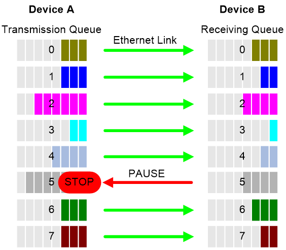
When congestion occurs on the local end, the device determines how to process received packets based on the 802.1p priorities carried in packets as follows:
· If PFC is enabled for the 802.1p priority carried in a packet, the local end accepts the packet and sends PFC pause frames to notify the remote end to stop sending packets carrying the 802.1p priority. The remote end stops sending packets carrying the 802.1p priority after receiving the PFC pause frames. This process is repeated until congestion is eliminated.
· If PFC is not enabled for the 802.1p priority carried in a packet, the local end drops the packet.
Restrictions and guidelines
You can configure PFC in system view or Ethernet interface view. When you configure PFC in system view and Ethernet interface view multiple times, the most recent configuration takes effect.
If you do not enable PFC on an interface, the interface can receive but cannot process PFC pause frames. To make PFC take effect, you must enable PFC on both ends.
To avoid packet loss, apply the same PFC configuration to all interfaces that the packets pass through.
If you configure generic flow control on a PFC-enabled interface, the following rules apply:
· The PFC configuration takes effect preferentially, and the generic flow control configuration is ignored.
· The generic flow control configuration takes effect on the interface only when PFC is disabled on it.
For more information about generic flow control, see Ethernet interface configuration in Interface Configuration Guide.
In an IRF network, follow these restrictions and guidelines:
· For IRF and other protocols to operate correctly, as a best practice, do not enable PFC for 802.1p priority 0, 6, or 7.
· As a best practice, do not configure PFC on IRF physical interfaces.
For information about IRF, see IRF configuration Guide.
For PFC to take effect in an overlay network, execute the qos trust tunnel-dot1p command. For information about the overlay network, see VXLAN Configuration Guide. For information about the qos trust tunnel-dot1p command, see ACL and QoS Command Reference.
PFC is supported only on the SC interface modules prefixed with LSCM2 and SD interface modules.
Configuring PFC on interfaces
Configuring PFC on inner interfaces
Restrictions and guidelines
This feature is supported only on the SF interface modules.
As a best practice, configure PFC on inner interfaces in the default MDC. Then, the configuration will be synchronized to non-default MDCs. For more information about MDC, see MDC configuration in Virtual Technologies Configuration Guide.
Procedure
1. Enter system view.
system-view
2. Enable PFC on inner interfaces.
priority-flow-control inner-port enable
By default, PFC is disabled on inner interfaces.
An inner interface is the inner Ethernet interface through which a card communicates with the device, and is invisible for users.
3. Enable PFC for 802.1p priorities on inner interfaces.
priority-flow-control inner-port no-drop dot1p dot1p-list [ headroom cell-count | ingress-buffer static threshold-value | ingress-threshold-offset offset-value | reserved-buffer reserved-value ] *
By default, PFC is disabled for all 802.1p priorities.
Configuring PFC on an Ethernet interface
1. Enter system view.
system-view
2. Enable PFC on all Ethernet interfaces.
priority-flow-control { auto | enable }
By default, PFC is disabled on all Ethernet interfaces.
3. Enable PFC for 802.1p priorities on all Ethernet interfaces.
priority-flow-control no-drop dot1p dot1p-list
By default, PFC is disabled for all 802.1p priorities on all Ethernet interfaces.
4. Enter Ethernet interface view.
interface interface-type interface-number
5. Enable PFC on the Ethernet interface.
priority-flow-control { auto | enable }
By default, PFC is disabled.
6. Enable PFC for 802.1p priorities.
priority-flow-control no-drop dot1p dot1p-list
By default, PFC is disabled for all 802.1p priorities.
Setting PFC thresholds
About PFC thresholds
The storage spaces for an interface include the following types:
· Headroom storage space.
· Shared storage space.
· Guaranteed storage space.
Setting PFC thresholds enables flexible control over PFC and can make good use of the storage spaces. The device supports the following PFC thresholds:
· Headroom buffer threshold—Maximum number of cell resources that can be used by packets with a specific 802.1p priority value in a headroom storage space. An interface drops received packets once this threshold is reached.
· Back pressure frame triggering threshold—Maximum number of cell resources that can be used by packets with a specific 802.1p priority value in a shared storage space. PFC is triggered once this threshold is reached.
· Offset between the back pressure frame stopping threshold and triggering threshold—When the number of cell resources used by packets with a specific 802.1p priority value decreases by this offset after PFC is triggered, PFC will be stopped.
· PFC reserved threshold—Number of cell resources reserved for packets with a specific 802.1p priority value in a guaranteed storage space.
Restrictions and guidelines
|
|
WARNING! After PFC is enabled for 802.1p priorities, the PFC thresholds use the default values, which are adequate in typical network environments. As a practice, change the thresholds only when necessary. |
You must enable PFC for 802.1p priorities before setting the PFC thresholds.
If you cancel PFC threshold settings on an interface, the PFC thresholds are restored to the state when only the priority-flow-control no-drop dot1p command is executed.
This feature is supported only on SF interface modules.
IRF physical interfaces do not support this feature.
Procedure
1. Enter system view.
system-view
2. Enter Ethernet interface view.
interface interface-type interface-number
3. Set the headroom buffer threshold.
priority-flow-control dot1p dot1p headroom headroom-number
By default, the headroom buffer threshold is not set.
4. Set the back pressure frame triggering threshold.
priority-flow-control dot1p dot1p ingress-buffer threshold
By default, the static back pressure frame triggering threshold is not set.
5. Set the offset between the back pressure frame stopping threshold and triggering threshold.
priority-flow-control dot1p dot1p ingress-threshold-offset offset-number
By default, the offset between the back pressure frame stopping threshold and triggering threshold is not set.
6. Set the PFC reserved threshold.
priority-flow-control dot1p dot1p reserved-buffer reserved-number
By default, the PFC reserved threshold is not set.
Configuring PFC deadlock detection
About this task
When packets carrying the specified 802.1p priority are transmitted in a loop, packets in the data buffer cannot be forwarded and PFC frames are repeatedly transmitted between devices. As a result, the cell resources in the buffer for device interfaces always cannot be released. In this case, the device enters the PFC deadlock state.
This feature periodically detects whether the device is in the PFC deadlock state. If an interface is always in the PFC XOFF state within the PFC deadlock detection interval, the device enters the PFC deadlock state. If PFC deadlock detection is recovered in automatic mode, the device automatically releases the deadlock state and recovers PFC and PFC deadlock detection after the delay timer expires. During the delay timer period, the device disables PFC and PFC deadlock detection on the interface, so that packets can be forwarded properly.
After the PFC deadlock state is released, the PFC deadlock detection feature can be recovered on the interface in automatic mode. Recovering this feature enables the PFC feature again at the same time.
Restrictions and guidelines
The specified CoS value must be within the 802.1p priority list specified by using the priority-flow-control no-drop dot1p command. To view the 802.1p priority for each CoS value, execute the display qos map-table dot1p-lp command.
This feature is supported only on SF interface modules.
Prerequisites
Before you configure PFC deadlock detection on an Ethernet interface, complete the following tasks:
· Enable PFC in auto mode or forcibly on the Ethernet interface.
· Enable PFC for 802.1p priorities on the Ethernet interface.
Procedure
1. Enter system view.
system-view
2. Set the precision for the PFC deadlock detection timer.
priority-flow-control deadlock precision { high | normal | low }
By default, the PFC deadlock detection timer uses normal precision.
3. Set the PFC deadlock detection interval for the specified CoS value.
priority-flow-control deadlock cos cos-value interval interval
By default, the PFC deadlock detection interval is not set.
4. Configure the delay timer for PFC deadlock detection automatic recovery.
priority-flow-control deadlock auto-recover cos cos-value delay delay-time
By default, the delay timer for PFC deadlock detection automatic recovery is not configured.
5. Configure the upper threshold for PFC deadlock times during the specified period.
priority-flow-control deadlock threshold cos cos-value period period count count [ down-auto-recovery | error-down ]
By default, the upper threshold for PFC deadlock times during the specified period is not configured.
6. Enter Ethernet interface view.
interface interface-type interface-number
7. Configure the action to take on the interface when the PFC deadlock times within the specified detection period reaches the upper threshold.
priority-flow-control deadlock threshold action { down-auto-recovery | error-down | turn-off }
By default, the action specified by the priority-flow-control deadlock threshold command in system view takes effect.
8. Set the port status detection timer for the ports that are shut down because the number of PFC deadlocks within the specified period reaches the upper limit.
shutdown-interval [ priority-flow-control ] interval
By default, the system does not automatically restore the port status.
9. Enable PFC deadlock detection on the Ethernet interface.
priority-flow-control deadlock enable
By default, PFC deadlock detection is disabled.
Configuring PFC deadlock prevention
About this task
A device assigns an incoming packet to a queue with an 802.1p priority based on the DSCP value of the packet and the DSCP-802.1p priority map. When packets carrying the specified 802.1p priority are transmitted in a loop, each node on the path stops transmitting packets with the specified DSCP values. In this case, a PFC deadlock occurs. To prevent PFC deadlocks, you can modify the DSCP-802.1p mappings for packets. The packets will be forwarded based on the new DSCP value.
This function enables the device to modify the 802.1p priority and DSCP value of packets when forwarding them.
Hardware and feature compatibility
This feature is supported only on the SF interface modules.
Restrictions and guidelines
A maximum number of two DSCP mappings can be configured, and the original DSCP values must be different.
Procedure
1. Enter system view.
system-view
2. Enter interface view.
interface interface-type interface-number
3. Configure DSCP mappings.
priority-flow-control dscp-mapping { original-dscp original-dscp-value to priority priority [ dscp dscp-value ] }&<1-4>
By default, no DSCP mappings are configured.
Verifying and maintaining PFC
|
|
IMPORTANT: The display priority-flow-control dscp-mapping statistics command is supported only on the SF interface modules. |
Execute display commands in any view.
|
Task |
Command |
|
Display the PFC information of interfaces. |
display priority-flow-control interface [ interface-type [ interface-number ] ] |
|
Display DSCP mapping statistics. |
In standalone mode: display priority-flow-control dscp-mapping statistics [ slot slot-number ] In IRF mode: display priority-flow-control dscp-mapping statistics [ chassis chassis-number slot slot-number ] |